

Electrical Power
Flooding & Underground Cables: Myth or Reality?
September 6th, 2021
Protecting Underground Cables
This Article was originally published by T&D World.
From Superstorm Sandy to Hurricanes Harvey, Irma, Maria, Florence and Michael – the volume of rain and storm surge has and can cause unprecedented flooding.
Flooding negatively impacts power systems – but not for the reasons you might think. Power Delivery Intelligence Initiative (PDi²) is taking on the myth that flooding compromises underground cables.
Medium and high voltage cables are designed to be direct buried, often in areas where they will be below the water table and permanently in a wet environment. Under normal weather conditions, manholes and vaults are often full of water and need to be pumped out for even routine inspections.
Outer jackets for these cables, made of polymeric materials, resist moisture permeation to prevent water incursion into the cable over the life of the system.

Roxtec Cable Transits provide effective protection to LV HV substation cables against flood damage and water penetration be it in dry or wet conditions.
In the rare instances that water permeates a cable jacket, certain insulations, including tree-retardant crosslinked polyethylene, are designed to resist growth of water trees that could cause premature cable failure. In addition, cable also can be manufactured using moisture-blocked conductor, water-swellable tapes and powders and corrugated sheath to make them more moisture impervious.
Underground cables are expected to meet rigorous standards specifically addressing operation under adverse weather conditions like flooding. These standards take into consideration both moisture and chemical resistance as there can be significant differences between rain and flood water. ICEA, ANSI and AEIC require adherence to a variety of test procedures that address moisture barriers, water-blocking components, water-resistance tests and other sealing components and technologies.

CSD RISE Duct Seals – combining ease of installation with cable duct sealing and protection against water, gas and fire.
Cables are rarely at fault for failures related to flooding.
The biggest concern for flooded underground systems are the open-air terminations at ground level where external or internal contamination has occurred due to poor sealing. However, technology is improving here as well.
Certain elbow and T-bodies are typically submersible and have not shown any significant negative impact after flooding. Joints and other accessories like link boxes are used in manholes and vaults and can be designed and installed in such a way that they can operate submerged in water without compromising cable insulation integrity.
Areas known for periodic flooding can take additional measures for outer protection of cable joints like metal housings moulded with epoxy coatings or fibreglass boxes filled with water sealants.
These designs are typically electrically screened with electrical fields that are fully contained within the solid insulation of the cable.
Myth – flooding and underground cables
busted.
Cables are made to resist water under both normal and extreme operating conditions. As long as water does not extend to the exposed terminations, there is little risk of failure due to flooding.
Where terminations are at ground level, technology and products exist to mitigate the chance of failure. These solutions should be part of storm hardening efforts and decisions regarding choices for new and rehabilitated power infrastructure.

Joint | Terminate | Connect Medium & High Voltage Cables MV HV
Further Reading
- Sealing Underground Cables & Pipes Under Constant Water Pressure
- Submersible Switch Applications By G&W Electric
- 21st Century Costs of Underground Distribution
LV, MV & HV Jointing, Earthing, Substation & Electrical Eqpt
Thorne & Derrick International are specialist distributors of LV, MV & HV Cable Installation, Jointing, Duct Sealing, Substation & Electrical Equipment – servicing UK and global businesses involved in cable installations, cable jointing, substation, overhead line and electrical construction at LV, 11kV, 33kV and EHV.
THORNE & DERRICK Product Categories: Duct Seals | Cable Cleats | Cable Glands | Electrical Safety | Arc Flash Protection | Cable Jointing Tools | Cable Pulling | Earthing | Feeder Pillars | Cable Joints LV | Joints & Terminations MV HV
Electrify The Future | Can Aluminium Really Beat Copper In Underground Power Cables?
August 4th, 2021
Underground power cables are playing an increasingly important role in the electrification of the world. The excellent conductivity of copper makes it appear the natural choice for the conductor material. But that isn’t always the case. Experience with France’s transmission grid has shown that aluminium can sometimes prove to be the superior option when a comprehensive life cycle assessment (LCA) is carried out.
Frédéric Lesur, Senior Engineer for high voltage cable systems and power grids, explains.
There are many criteria that must be considered when selecting the conductor for an underground cable system. These include electrical considerations, thermal design, installation techniques, mechanical stresses and so on.
And of course, cost is an important factor, not just the purchase cost but the overall cost of operating the cable throughout its life. Environmental impact is also an increasingly important factor at the earliest stage of the cable design.
Electrical resistance
For underground cables, only two metals are used: copper (Cu) and aluminium (Al), due to their excellent conductivity. The best metal for conducting electricity is actually silver. Unexpectedly, gold comes in at third place – behind copper, while aluminium is fourth.
Copper has much better electrical conductivity than aluminium – by a factor of 1.64.
But it is over three times heavier and much more expensive. Copper prices can fluctuate considerably, but there have been times this century when the cost of copper has been five times that of aluminium.

Figure 1 – Extruded XLPE cables with aluminium and copper conductors
What these factors mean is that while an aluminium conductor must be bigger to carry the same current as copper, the aluminium cable can be more cost-effective to purchase and easier to handle.
There are a few variations such as enamelled copper wires (CUE) or oxidized aluminium wires.
Experience in the French grid
As a concrete example, Figure 2 illustrates cable ratings calculated according to the IEC 60287 standard for different types and sizes of conductor. This is based on a typical French installation in a semi-urban area, with the cables laid in PVC ducts embedded in concrete with a trefoil geometry.
It is interesting to note the relative performance of the conductors. In one example, a 2500sqmm Al cable has very close to the same rating as a 2000sqmm Cu cable.

Figure 2 – Current ratings of conductors installed in France. The figures on the x-axis indicate the conductor cross-section eg 2000sqmm
Losses caused by conductors
Losses in the conductor account for the major proportion of the energy lost in an underground cable. Figure 3 shows the typical total losses for cables installed in France as a function of their current rating. The curves end at the steady-state permissible current rating, associated with the maximum temperature of the insulation material (90°C for XLPE = cross-linked polyethylene). The order of magnitude is 30 W/m per cable.
")
Figure 3 – Total losses dissipated per cable type and size (W/m)
Réseau de Transport d’Electricité (RTE), the French transmission system operator (TSO) has produced statistics showing that underground cable systems operate more than 95% of the time at a current rating lower than 60% of their maximum rating. This means that the losses are normally well under their maximum value. The remaining 5% of the operating time matches with the peak values and most constraining conditions, such as in a severe winter period with extensive use of electrical heating.
The conclusion is that an underground cable is therefore operated generally in conditions leading to “acceptable” losses. This point is essential, considering that power losses dominate the cable’s environmental impact. The closer to the maximum point the cable is operated, then the greater the environmental footprint and the higher the operational cost.
Economical design of cable conductors
When designing a cable system the aim is to stay within the current rating dictated by thermal behaviour. Effectively, the cable is designed not to exceed the maximum temperature of the insulating layer in any operational mode. Most of the time, the design engineer will select the size of conductor that allows the required operating temperature while staying on the safe side within a wide range of standardized sizes.
Until recently, this approach was regarded as offering the lowest investment cost. However, the global cost of a power link also depends on the actual cost of the energy losses. A bigger conductor, although more expensive on initial purchase, may generate lower losses than the thermally designed conductor. Therefore, it can become significantly more cost-effective after a few decades.
This approach is explored in Figure 4 that looks at the case for a cable system carrying 700 A.
Data is plotted on the graph as a function of the conductor size (two colours are used for Al and Cu conductors) and the investment cost of the installed system. The investment cost is made up of the actual cost of the losses at the specified current rating and the total cost.

Figure 4 – Investment cost + actual cost of losses = total cost during the economic life of the cable
The investment costs increase with the conductor size, while the cost of losses decreases as there is less electrical resistance. The combination of both trends leads to U-shaped curves with an optimal conductor size. In the example, 1600sqmm Al is the most cost-effective conductor to transmit 700 A over a project life of 50 years. Yet, 630sqmm Al would have been selected from a strict thermal design point of view.
This optimisation is not only of an economic nature. The lower losses also play a favourable role in terms of environmental impact. The benefits can include less risk of thermal aging, reduced risk of thermal runaway due to uncontrolled soil drying, a larger safety margin to handle load peaks or unexpected hot spots, margins for overloads, etc.
Furthermore, lower losses help in limiting global warming.
The prospects for very large aluminium conductors
While maximum standardised cross-sections of conductors have moved from 1600 to 2500sqmm within recent years, some manufacturers are now offering new solutions with aluminium conductors of 3000sqmm or 4000sqmm, pushing the present limits of copper conductors.
Studies have been carried out to assess the interest in these huge components in terms of performance, installation, economics and environmental impact. They show that, for a given current rating, a cable with a very large aluminium conductor generates less energy losses than a cable with a smaller copper conductor of one or two sections.
The lower investment cost of the resulting aluminium cables could bring significant savings, despite the increased cost of installation (excavation, cable laying, assembly of joints, etc.). Design engineers then have to balance the attractive global cost with a number of additional constraints.
These include increased civil works, more rigid conductors and lower strength to resist pulling during installation, increased size of drums or lower delivery length on site, which means shorter sections and more cable joints. A larger conductor diameter also involves accessories of bigger size.
Perhaps the most significant barrier is that there is currently no experience in terms of the qualification of such huge cable systems.
Utilities and manufacturers will need to collaborate to address this challenge. However, at the conductor sizes used today there is substantial practical experience showing clearly that aluminium represents an important alternative to copper.
Thorne & Derrick
Nexans Main UK Stockist & Distributor
Contact us for Competitive Prices & Fast Delivery from Stocks for Heat Shrink, Cold Shrink & EPDM Rubber Connectors, Joints & Terminations up to 66kV.
Thorne & Derrick International are specialist distributors of LV, MV & HV Cable Accessories, Jointing, Substation & Electrical Equipment – servicing UK and global businesses involved in cable installations, jointing, substation, overhead line and electrical construction at LV, 11kV, 33kV, 66kV and EHV.
Stocking & Supplying | Duct Seals | Cable Cleats | Cable Glands | Electrical Safety | Arc Flash Protection | Jointing Tools | Cable Pulling Eqpt | Earthing & Lightning Protection | Feeder Pillars | Cable Joints LV | Joints & Terminations MV HV

Euromold MV HV | Cable Terminations, Connectors, Elbows & Joints
How Can I Connect To An Electricity Network? | UKPN Guide
June 30th, 2021
How can I connect to the electricity network?
An article from UKPN
As an Independent Connection Provider (ICP), we understand that your new electricity connection needs to be delivered in a safe, reliable and cost effective way. We have a long track record throughout the UK of successfully meeting clients’ power requirements through the design and build of electrical infrastructure, from the point of connection to the local distribution network to their onsite infrastructure.
Our Team of Experts
- Are National Electricity Registration Scheme (NERS) accredited as an independent connection provider for contestable works.
- Provide a nominated Project Manager for every connection so you know someone is always on hand for progress updates and to make sure any questions are dealt with in a timely manner.
- Work collaboratively with our clients to ensure delivery programmes are agreed, progress is regularly monitored and deadlines are met.
- Support customers to develop their requirements, taking account of current needs and future aspirations, supporting business objectives and sustainability goals.
- Apply industry best practice and integrate the latest in emerging technologies to develop connections solutions that encompass grid connection through to onsite infrastructure needs.
- Work closely with the local DNO to ensure seamless delivery of connections on time, every time.
How we can help
As an established ICP, we support our clients to ensure their new connection requirements are safely delivered to the highest standard, on time, in the most cost effective and innovative way.
Our extensive in-house capability, including designers, planners, authorised engineers and project managers are experienced in designing and building complex and essential electricity distribution networks.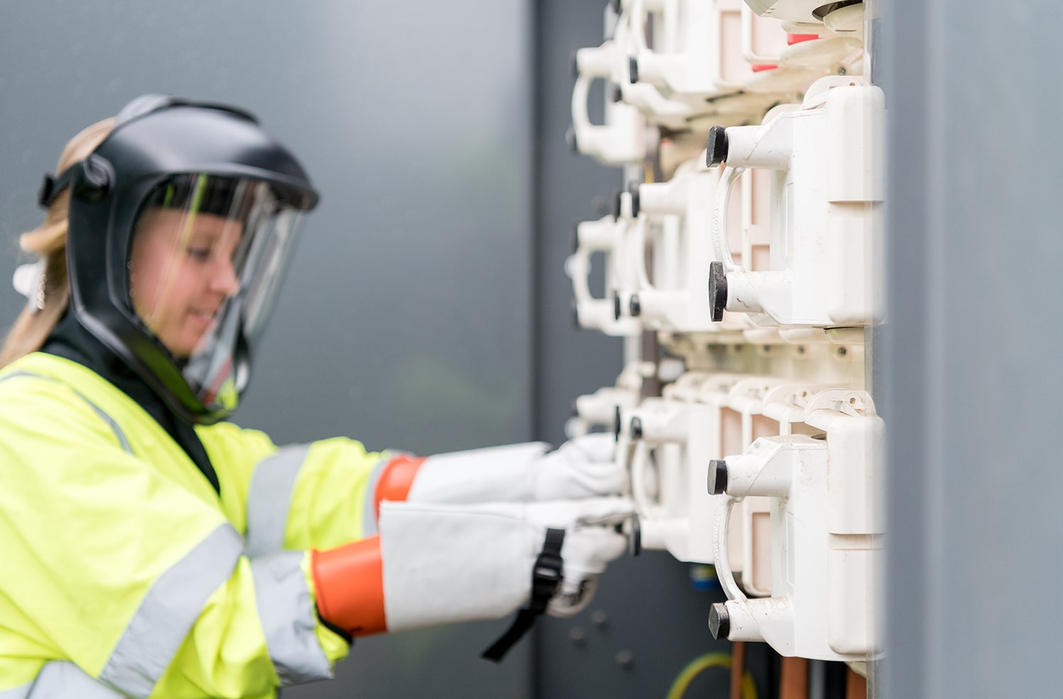
In addition to the connection work, we can support you by taking a long term, holistic view of your energy infrastructure. Our range of solutions enable us to provide an end-to-end service to reduce your energy bills, decarbonise your assets and improve the resilience of your electricity network. Whatever your needs we will work with you to deliver a customised solution.
You can trust us. We have been delivering for some of the UK’s most critical electricity infrastructure for over 50 years, including High Speed 1, Network Rail, London Underground, Docklands Light Railway, and EDF (Hinkley Point C). We also deliver for leading UK airports, Heathrow, Gatwick, Luton, Stansted and London City.
UKPN deliver work associated with a connection to the distribution network, including:
- Cable laying (LV, 11kV, 33kV & 132kV)
- Diversion or reinforcement of LV, 11kV or 33kV circuits
- Diversion or reinforcement of substations
- Erection of new overhead lines
- Installation of substation plant
- Cable jointing and termination

FAQs
How can I arrange connection to the distribution network for a new development?
It’s straightforward, just let us know where your development is and what your requirements are and we will provide you with a proposal for the connection to the distribution network. We will make the necessary arrangements with the local DNO, or IDNO, and ensure any work they have to do is coordinated with our works.
How can I ensure my development capacity requirements are met?
We will work with you to understand your capacity requirements and design the optimum solution to meet those requirements. Our design engineers will work with the local DNO, where necessary, to identify the preferred point of connection to the distribution network to meet your expected demand. We also have experienced in-house consultants who can help you determine the most suitable technical and commercial solution for your entire development if required.
How can I be sure the connection will be energised in line with the site construction programme?
We understand the importance of meeting the delivery programme for connection to the distribution network for a new development. Our experienced designers, planners and engineers work closely with you, and your partners, from outline design through to construction on site to ensure your deadlines are achieved.
How can I reduce the cost of Connection to the distribution network?
By utilising our local in-house resources and an efficient and effective supply chain, our ICP Solution Offering is a competitive alternative to other providers. We ensure our proposal for the connection to the distribution network includes for the most cost effective design whilst also ensuring resilience and quality is maintained.
How can I be sure the electrical infrastructure is built to the optimum quality and in line with the correct standards?
Our knowledgeable design engineers understand electricity networks and make sure quality is at the forefront of all designs. We are experienced with Distribution Network Operator standards and, being closely affiliated with one of the UK’s largest DNOs, we take pride in operating to the highest quality and industry leading standards. Our experienced training resources, make sure we keep up to date with industry developments.
Further Reading
UKPN | Joints, Terminations & Separable Connectors 11kV 33kV
Pot Ending LV SWA PVC Sheathed Service Cables – Engineering Guide UKPN
11kV Triplex Cable Joint (UKPN)

LV MV HV Jointing, Earthing, Substation & Electrical Eqpt
Key Product Categories: Duct Seals | Cable Cleats | Cable Glands | Electrical Safety | Arc Flash Protection | Cable Jointing Tools | Cable Pulling | Earthing | Feeder Pillars | Cable Joints LV | Joints & Terminations MV
Brecon Power Short-Term Operating Reserve (STOR) Plant | Powersystems UK
June 16th, 2021 Plant | Powersystems UK")
This article has been republished with the kind permission of Jules Daly, Marketing & Communications Manager at Powersystems Ltd (High Voltage Electrical Engineering).
About Powersystems
Powersystems was established in 1977 to provide industrial customers with the expertise that only the local electricity board previously offered. 40 years on Powersystems are still supporting some of their first customers a testament to the service provided. Continued support of these industrial customers and increased activity in the grid connections and renewable energy markets has been the core of Powersystems success.
 Plant | Powersystems UK")
- Name of Client and Location: Quinbrook Infrastructure Partners (Rassau NP23 5SD)
- Project Value: £12m
- Duration of the Project: 9 months first export to Grid November 2018. Electrical works July 2018 – February 2019
- Services: Electrical Infrastructure, Balance of Plant (eBoP)
- Market Sector: Short Term Operating Reserve (STOR)
- Powersystems Fact: Powersystems your high voltage specialist partners – Powersystems team have connected 100 MW of short term operating reserves.
Brecon Power STOR
Powersystems high voltage (HV) power engineering were responsible for the design, installation, testing and commissioning of the electrical infrastructure associated with the construction of the 21MW embedded short term operating reserve (STOR).
The plant was designed to provide reserve electricity generation to the National Grid which can be called on at short notice at times of network ‘stress’.
The principle of the development and its impact on environmental, social and economic factors was carefully assessed and given the go-ahead.
The site is located in Brecon, mid-Wales and was constructed in partnership with Jones Bros Civil Engineering on behalf of the client, Quinbrook Infrastructure Partners. Brecon STOR adds gas-peaking generation to their extensive worldwide investment portfolio that includes renewable and low carbon technologies.
Brecon Short-Term Operating Reserve (STOR) plant is a 21MW gas peaking generation platform which began exporting power to the grid in November 2018. The site consists of fourteen 1.5MW generators powered by Jenbacher Engines supplied by Clarke Energy which are capable of supplying electricity to the grid at short notice. As a trusted NERS accredited company with over 40 years’ experience, Powersystems were appointed to assume the responsibility for the electrical and mechanical Balance of Plant.
Brecon Power STOR development
As the UK’s electricity network continues to move away from large-scale carbon emitting sources towards alternative renewable generation, it faces new challenges.
The intermittent nature of renewable sources such as wind power make it impossible for the grid to accurately predict how much energy they will have at their disposal at any one time, or how long they will need it for.
Brecon Short Term Operating Reserve (STOR) plant is one of many STOR sites across the UK that give the grid the extra flexibility it needs to meet peak demands at short notice and ensure smooth and efficient operation.
Also known as a ‘peaking’ plant the STOR plant provides electricity generation at short notice to the electricity network.
The National Grid owns and operates the national electricity network. They are obliged to ensure that the electricity supply system runs within specified limits. Many factors change these operating conditions, but none more so that the balance between the electricity demanded by customers and the electricity generators available to produce electricity.
Conventional power generation equipment can be operated with some certainty, however the increasing supply of energy from renewable sources, such as wind turbines and solar arrays, means that some power generation is reliant on prevailing weather conditions, which can create a shortfall in supply. These shortfalls are required to be replaced at short notice and for this reason the National Grid requires a number of plants across the country capable of producing small amounts of electricity at short notice.
The Brecon power STOR comprises of fourteen ‘engine-driven electricity sets’ that together create a total of around 21 MW energy. Each engine generator set is sited in its own acoustic containment cell, side by side within a new plant building. The engines are fuelled by natural gas and will use conventional spark ignition technology to burn the fuel which in turn rotates the generator, creating electricity that is exported to support the local electricity network.
The generators had to connect to a common switchboard and control system in order to provide an interface to the Western Power Distribution (WPD) substation. The engines also required a natural gas supply and hot water flow/return with duty/standby equipment in order to facilitate a fast start capability.
The engine exhaust gases pass through a silencer before being expelled to the atmosphere. As the fuel is natural gas the exhaust emissions are similar to those expelled by a conventional gas-fired central heating boiler. The heat generated by the engines is dissipated in radiators cooled by electric fans. The engine cooling system is a closed loop water system which continues for as long as the plant is operating. By its very nature, i.e. providing short term reserve power at short notice at times of network ‘stress’, the plant runs for short periods of time with long periods between operating times.
Experience showed that this is infrequent and that STOR facilities are typically called on for around 60-90 minutes every 2-3 day, which equates to around 300 hours per annum. This period of time is typical in the current market, though actual usage may vary according to supply and demand and network ‘stress’.
Scope of Electrical works
The major items of electrical plant that Powersystems designed, supplied, installed, and commissioned were for the design, supply, installation, testing and commissioning of the 33kV grid connection consisting of:
The major items of electrical plant that Powersystems designed, supplied, installed, and commissioned were:
- 7 x 3.5 MVA 33 kV/0.4 kV transformers and associated bunds
- Gas supply connections to 14 x 1.5 MW Clarke Energy generators via HDPE and stainless pipework
- Boilers and hot water pump & distribution system, including Insulated flow and return pipework
- Cabling for the control and protection panels for the complete system
- Compound and sub-station earth system installation and testing
- All necessary building fit-out works comprising Lighting and small power with intruder, CCTV and fire alarm systems
- Within the Brecon power site, the installation of 33kV power, low voltage, control, signal and communications cabling works
Brecon Power STOR project timings
Construction of Brecon Power STOR began in June 2018 with mobilisation on site which involved preparing the ground for construction activity. Generator component deliveries commenced in July 2019.
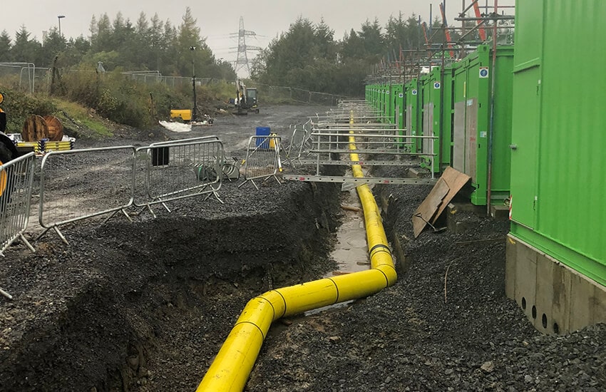
Brecon Power STOR Gas Pipework in ground
How Powersystems helped
Powersystems engineers were involved with a design that maximises the generation capacity on the small amount of land available whilst also adding cost-effectiveness for the customer.
Instead of connecting each of the fourteen 1.5MW Clarke generators to their own 33/0.4MW transformer, valuable space on site was saved by using three-winding transformers shared between pairs of generators instead. This halved the number of step-up transformers needed to 7.
Through condensing the site layout, Powersystems were able to save the customer on some of their largest expenditures – the amount of underground utilities needed to support the site. This included reducing the length of gas and hot water pipework as well as the onsite underground cabling.
Noise considerations were also at the forefront of the design with consideration for the site’s surrounding neighbours a high priority. Studies were conducted to assess the impact of noise and measures were put into place to reduce this. The noise of the generators was primarily reduced by fitting engine silencers to the equipment.
In order to secure preferable tariff arrangements between the customer and the National Grid, an energisation date was set for December 2018. To achieve this, Powersystems engineers worked with the customer to push non-critical aspects of the project back beyond this date. This resulted in the customer being able to export power at the set target date to avoid costly penalties.
- Electrical design
- Interface with Western Power Distribution for status & constraint signals
- Switchgear installation and commissioning
- Transformer installation and commissioning
- Gas pipework supply, installation & testing
- Hot water system design, supply, installation & testing
- Cables & containment design, supply & installation
- HV testing
- SAP provision
- Backup generator supply
The results:
Environmental Benefits
- Low carbon power platform
- Flexible peak power generation
Economic Benefits
- By reinforcing the national grid, the plant is of “indirect benefit to industry in the area”. The plant brings varied employment opportunities including management, maintenance and security staff to the area – people who “would be recruited locally where possible”
- The Brecon power STOR plant fulfils an increasingly important means for the National Grid to maintain system stability in light of the country’s increased reliance upon the generation of energy from less predictable renewable resources
- The Brecon power STOR (fast reserve plant) provides a low carbon back-up power generation to the National Grid. A key component that helps with the capacity market is the Short-Term Operating Reserve (STOR). These reserves are used to help the national grid combat exceptionally high demand or cover normal demand in the case where a plant is unavailable
- Brecon Power is a part of a potential $1.6B worldwide investment in low carbon energy
Project Facts and Figures
- Number of generators: 14
- Generator capacity: 1.5 MW
- Total Installed capacity: 21 MW
- Connection Voltage: 33kV
- Fast start response time: 60 seconds
- Altitudes of site: 1250ft
- Length of onsite 33 kV cabling: 1.75 km
- Length of onsite 400 V cabling: 3.0 km
- Length of onsite control & signal cabling: 6.0 km
- Used pre-insulated pipework with compression joint technology to significantly reduce installation timescales (no onsite welds, pre-insulated)
- Low-carbon technology producing 60% less CO2 emissions than coal or oil
- Powersystems are a Lloyds registered (NERS) approved independent connection provider (ICP)
 | Battery Storage | Data Centres | Oil & Gas | Manufacturing | Substations Switchgear Transformers | Rail | Hazardous Areas")
LV MV HV Electrical Safety Equipment & Arc Flash Protection Clothing | Renewables (Solar & Wind Onshore Offshore) | Battery Storage | Data Centres | Oil & Gas | Manufacturing | Substations Switchgear Transformers | Rail | Hazardous Areas
Further Reading
- Green Hydrogen A Renewable Energy Technology
- Why Large Offshore Wind Farms Should Double Their Intra-Array Voltage
THORNE & DERRICK
SPECIALIST ELECTRICAL DISTRIBUTOR
Thorne & Derrick distribute the most extensive range of Cable Installation & Electrical Distribution Equipment to the Power Transmission & Distribution industry in the onshore and offshore wind, solar, rail, oil/gas, data centre, battery storage and utility sectors.
We service UK and international clients working on underground cables, overhead lines, substations and electrical construction at 11kV and up to and EHV transmission and distribution voltages.
- Key Products: MV-HV Cable Joints & Terminations, Cable Cleats, Duct Seals, Cable Transits, Underground Cable Protection, Copper Earth Tapes, Cable Jointing Tools, Feeder Pillars, Cable Ducting, Earthing & Lightning Protection, Electrical Safety, Cable Glands, Arc Flash Protection & Fusegear.
- Distributors for: 3M Cold Shrink, ABB, Alroc, Band-It, Catu, Cembre, Centriforce, CMP, Elastimold, Ellis Patents, Emtelle, Furse, Lucy Zodion, Nexans Euromold, Pfisterer, Polypipe, Prysmian, Roxtec.

LV – Low Voltage Cable Joints, Glands, Cleats, Lugs & Accessories (1000 Volts)

MV HV – Medium & High Voltage Cable Joints, Terminations & Connectors (11kV 33kV EHV)
![]()
Understanding Battery Energy Storage Systems (BESS) and Power Arbitrage By SPE Electrical Ltd
June 15th, 2021
 and Power Arbitrage By SPE Electrical Ltd")
This article has been republished with the kind permission of SPE Electrical Ltd.
SPE Electrical Ltd
SPE Electrical are based in Dorset, in the South West, but serve the whole of the UK as well as many international clients.
The company was created in early 2006, in recognition of the rapidly expanding infrastructure and energy sectors, and the associated need for specialist HV consultancy services. To date their power system consultants have undertaken a wide range of studies for a variety of local, national and international clients.
The company specialise in all aspects of design, analysis and consultancy that relate to large power system and have design experience from low voltage to 400kV, and covers industries as diverse as renewable power to water treatment plants. SPE Electrical Ltd are also well versed in international design standards and practices such as IEC, ANSI, IEEE, NEC and NFPA, and their engineers have worked on projects all around the globe.
Battery Energy Storage Systems – Power Arbitrage
Part 1: Introduction
Battery Energy Storage Schemes are very versatile plants and can be used for a number of different services, depending on the plant design and aims; this can include services such as power arbitrage, voltage control, and the new Dynamic Containment (DC) service which replaces the old Enhanced Frequency Response (EFR) service. BESS units can also be used as a power balancing service, to meet shortfalls in power, to limit disturbances from the grid during transient switching events, where a plant has large dynamics loads, such as big motors and generators that switch in and out frequently.
At SPE we have found that many developers are keen to add battery storage systems into their existing projects, but are often unsure exactly how the battery will be used. This leads to the dilemma of trying to design a system that will be flexible enough to allow future revenue streams, without pre-investing for expensive system upgrades.
This first post gives a simple guide to explain the basic ideas of how a BESS works and looks at their role in providing power arbitrage.
Part 2: BESS Basics
Before we get into the specifics, it is worth covering a couple of basic ideas of what a BESS is and how it operates. First off, the term BESS is generic name for an electronic Power Conversion System (PCS) i.e. inverter, coupled with some form of battery. From the DNO and TSO perspective the battery doesn’t actually matter too much, and it is the PCS that is really of interest.
The battery can be anything from old car batteries, to modern li-Ion batteries, or more advanced cryo-batteries or flow batteries.
The battery type just determines how much energy can be stored and how quickly it can be converted from chemical form to electrical energy.
Second, a simple concept that is often misunderstood is the difference between power (MW) and energy (MWh). A BESS rated at 1MW & 1MWh can provide 1MW for an hour, of 0.5MW for 2 hours, or 0.25MW for 4 hours etc. but it can never provide more than 1MW, because this limit is imposed by the inverter rating and system design. From the DNO perspective the amount of MW is important, as this governs the main power flows in their network.
This leads to our third point, which is that of power swings. Simple MW flow is easy to understand from DNOs heat maps, but the ability of the DNO network to cope with large power swings is much less clear and usually needs some analysis.
For power swing, we are referring to the speed at which the BESS needs to change from import to export and vice versa. For power arbitrage this is very slow and doesn’t cause a significant power swing, but for fast response services like DC, the power swing can be significant with a 50MW BESS, potentially going from full export to full import in 1s, giving a 100MW/s power swing – which would challenge the most robust of power systems. This is why the G99 forms ask for the ramp rate of the BESS. This is bit of a tricky area, and often a major constraint, which we will go through in another post.
Our third point is that a BESS can provide reactive power as well as providing active power, and importantly it can provide reactive power at the same time, which is useful for regulating voltage on the DNO network. Provided the BESS is correctly sized, it could easily provide 20MW of active power and 20MVAr of reactive power.
So, when preparing a grid application for a BESS it is important to understand what services we are hoping to provide to the system and what the local limitations are.
The DNO or National Grid, typically want to know the MW capacity of the site, and the worst-case power swing as well as any reactive power flow capability, as these are what will affect their system behaviour and responses, but are not usually that interested in the MWh rating of the system.
Part 3: Power Arbitrage
The power arbitrage service of a BESS is technically and commercially the simplest concept for battery storage. It is based on the simple premise of absorbing energy when it power is cheap, such as at night or when there is excess power from CHP or solar array, and then discharging the battery during peak load times. The benefit of such an approach allows what is known as load demand curve shifting, where the excess power from renewables (often solar) is stored at high production times / low demand then discharged at low production times / peak demand.
This has two main benefits. Firstly, and depending on the profile, high tariff electricity costs can be avoided, and a flat charging profile created. Secondly, it means that the size of the grid connection can potentially be reduced, although one needs to consider what happens if there was a shortfall in the surplus power i.e. a very cloud day, if the surplus comes from a Solar PV array.
The revenue streams here are obviously limited to the cost of energy creation and storage at cheap times, compared to the cost of energy during high tariff times, and is based on the concept of peak shifting the energy demand, so that it is balanced more evenly across a 24 hour (or whatever other timeframe). In the authors opinion, this is the ‘holy grail’ of most BESS units and The System Operators (TSO), an electrical system demand that is predictable, and therefore easy to plant and dispatch. In practice to achieve, this the BESS has to be cheap and robust enough to store and dispatch energy as needed, and when is most economic to do so.

Figure 1: Diagram Showing Power Arbitrage Concept
With power arbitrage, the charge and discharge of the BESS is usually very slow, and this will not overly stress the host electrical system or the DNO system. From a design point of view, compliance with the ENA P28/2 standard is not usually an issue, but a large battery systems can contribute significantly to the system harmonics and voltage flicker due to the power electronics operation, which usually needs some careful analysis to ensure compliance.
A less obvious use of a BESS is using it as a power store to support starting and operation of a heavy consumer of power. Let us say for example you have a heavy industrial plant that you want to add a new 10MW motor to. Starting these motors is always a complex process, but fortunately ones that a Variable Speed Drive solves easily, but what happens if your grid supply to the DNO is maxed out and an upgrade will cost millions. Simple(ish), you install a BESS and charge it up overnight, then discharge it when the new drive needs to operate. The DNO does not see any additional power demand and no network upgrades are needed.
Part 4: Applications – Power Arbitrage & Balancing in a Water Treatment Works (WTW)
For an application example, let us consider an example of a Water Treatment Works (WTW) that is hoping to achieve carbon neutral status within the next 5 years. WTW sites are interesting ones to study, as they tend to have a mix of large varying loads such as pumps and compressors, and plenty of space to install Solar PV and a BESS and carry out the tie-ins between the new and existing plant. It should be noted that for our analysis, the site type doesn’t really matter as the principles are the same.
So how does power arbitrage work with a battery storage system work? This is best understood with an example. First, we start with the basic premise, that the plant owner has assessed their DNO connection and there are no problem and second that site has enough space to install a fair sized Solar PV array of 5-10 MW. Next, we look at the site power consumption, this is usually very dynamic, but lets pretend for a moment, that we can simplify things a bit and say they have an average steady state consumption during the day of 2MW, and at night-time it drops to 0.5MW. Our basic specification might look something like this:
- Space to install 5-10MW Solar PV array.
- Available HV point for tie-in.
- Desire to achieve full carbon neutral operation.
- Site load profile is simplified to a consistent value of:
- 2 MW approximately constant load between 8am and 7pm (11 hours) = 22MWh
- 5MW constant load between 7pm and 8 am (13 hours) = 6.5MWh
Simple deployment of a solar PV scheme would certainly help the asset owner, as the power produced by the Solar PV would offset the power consumption of the WTW by a significant margin. However, the problem would be that either the Solar PV would be oversized and during peak daylight hours would be exporting power, or it would be undersized, and not fully offset the power demand, and in both cases the night-time power demand would still be needed. This presents a dilemma for the asset owner, as neither scheme meets the objectives, but by adding a BESS into the mix, we can possible meet all the target goals.
Next, let’s do bit of basic maths to see what works, to calculate average any usage, energy storage capacity and so on. This can be done in a number of ways, depending on the level of sophistication desired, at the most basic, a simple Excel and graphical model can be generated of the load and generation profiles, but it is relatively easy to create more advanced mathematical models of the system, using various integration methods and piecewise linear functions, or directly in simulation package like Matlab. For the purpose of this post we will go for an easy Excel approach.
In the below diagram we can see a simplified power generation diagram shown in block format for the power generation (green), power demand (red), excess PV discharged into the BESS (blue) and power discharged from the BESS (yellow).

Figure 2: Simplified Block Diagram Showing Power Arbitrage Calculation
From the above plots we can see that we get a pretty good power balance, with around 2MWh spare capacity from the Solar PV system, which we can account for with intermittency, shading and other losses. We do can do some more simple maths and we can roughly dimension our PCS and battery size, as follows:
- The solar PV is sized to give a peak output of 5MWac.
- The battery PCS size has to be equal to the largest difference between the plant demand and the solar output. This occurs in the evening when power demand is still high and the solar output has fallen to near zero . I.e so the delta is 1 MW.
- We can see from the above that we need the BESS to be able to deliver 10.5 MWh.
- Our final design is therefore a 5 MW PV array coupled with a 1 MW BESS with a 10.5 MWh energy store.
Part 5: Summary – Power Arbitrage
The above is obviously very simple analysis, representing a simple Solar PV curve, and not accounting for probability and differing irradiance levels during the day and seasons. Likewise, the load is likely to significantly more variable than the simplified model shown. The thing to remember here, is that the post just shows a simple model for demonstration purposes, to show a principle of how a system could be made to work.
In practice, it is usually not economic to design a Solar PV and BESS system that achieves full carbon offset, because of the inherent probabilistic values in the irradiance levels. However, with some careful analysis and a bit of time, a Solar PV and BESS can go along way to meeting this target. The above example is for a WTW but would work just as well, for a large factory, or country estate. Of course, adding in a BESS to a brownfield site is never quite that simple, so it is usually necessary to carry out some surveys, and identify if the equipment is suitably rated for the increased duty and then identify the necessary tie in location.
It should also of course be noted that we have considered Solar PV and a battery storage solution here, but the principle applies to any intermittent renewable, such as wind power or wave power and any other storage technology, such as hydro, compressed air / gas etc. One final thing we can do with the new system, is to run the Solar and BESS at a slightly lagging power factor (producing MVArs) so the site is held at unity PF and even greater savings are achieved. If you would like to discuss your project requirements, please get in touch.
THORNE & DERRICK
Thorne & Derrick are national distributors of LV, MV & HV Cable Installation, Jointing, Substation & Electrical Equipment – servicing businesses involved in cabling, jointing, substation, earthing, overhead line and electrical construction at LV, 11kV, 33kV, 66kV and EHV. Supplying a complete range of power cable accessories to support the installation and maintenance of low/medium and high voltage power systems:
- Slip-on Cable Terminations
- Cold-shrink Cable Terminations
- Heat-shrink Cable Terminations
- Cable Joints – Heat & Cold-shrink
- Separable Connectors (Euromold)
- Surge Arresters & Switchgear/Transformer Bushings
Key Product Categories: Duct Seals | Cable Cleats | Cable Glands | Electrical Safety | Arc Flash Protection | Cable Jointing Tools | Cable Pulling | Earthing | Feeder Pillars | Cable Joints LV | Joints & Terminations MV HV

