Insulating matting is a essential component of electrical safety and is specified and installed to provide protection against electrical shock and hazards around electrical equipment, such as switchboards and switchgear – this can include Low Voltage, Medium Voltage & High Voltage.
As part of a facilities standard risk assessment, where a potential for electrocution is present, then electrical insulating safety matting (commonly referred to as switchboard or switchgear matting) is recommended in the HSE’s Safe Working Practices for Electricity At Work document (HSG85) where it references BS EN 61111: 2009 (Live Working: Electrical Insulating Matting British Standards Institution).
“providing and using correct personal protective equipment (PPE) to reduce the risk of contact with live parts or earth, eg insulating gloves, insulating matting (see BS EN 61111:200917). If there is a risk of burns from arcing or flashover that cannot be avoided, consider the use of adequately rated, thermally insulating, flame-resistant, arc flash clothing or PPE (including face/eye protection).” HSG85
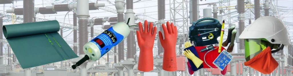
The range of CATU insulating matting conforms to the standards set out in IEC 61111 and provides MV-HV electrical protection for personnel working on medium and high voltage switchgear, switchboards, control panels and transformers.
The IEC 61111 standard sets out the requirements that must be met and supersedes the standard CLC/TS 61111:2006 and includes the following significant technical points:
General review of the requirements and test provisions
Modification of the test procedure for slip resistance matting
Specification of standard and alternative types of electrodes for the proof test
The conditioning time for low temperature folding test of insulating matting
IEC 61111:2009 is applicable to electrical insulating matting made of elastomer for use as a floor covering for the electrical protection of workers on electrical installations, including 11kV and 33kV substations.
LV MV HV Insulting Matting Explained
Selection of insulating mats for specific applications depends on the worker exposure to operating voltage and matting is tested to withstand certain specified voltages – referred to as the safe working voltage detailed below. Electrical safety matting is tested to a higher voltage than the certified use voltage – the voltage at which the matting is certified to is the Safe Working Voltage.
CATU Electrical insulating matting is specified and tested to IEC 61111 Category C with working temperatures to – 40°C for the following voltages:
Products that are covered by the IEC 61111 standard include live working, electrical insulating materials, insulating matting, elastomers, floor coverings, electrical safety, electric shocks, safety devices, occupational safety, classification systems, grades (quality), marking and testing.
See live working tools for further information about insulated tools in accordance with IEC Standards for working on energised low voltage cables.
Protecting Jointers & Electrical Engineers When Working Live On Cables & Switchgear – comprehensive ranges of insulating matting and insulated tools.
Catu Electrical insulating matting
Electrical insulating matting is available in roll form for placement and rolling-out in front of medium/high voltage switchgear rooms, motor control centres (MCC), traction power substations and UPS rooms.
Portable pre-cut insulating mats are available to provide protection to site engineers and cable jointers working on electrical installations in plant and lift control gear rooms – often used to provide electrical protection when 11kV/33kV jointing, terminating and glanding cables into electrical distribution equipment.
Complete range of LV-HV Insulating Matting for all medium and high voltage switchgear, switchboard and substation electrical safety protection up to 33kV.
Recommendations For Use & Storage of Matting
It is vital to store and use electrical insulating mats in the correct manner in order to prolong their lifespan and ensure they continue to function and provide the insulation levels required. When storing or transporting the matting it should be properly stored and should not be bent or deformed.
The insulated mats should also not be stored or used close to any excessive heat sources or exposed to direct sunlight for long periods. The ideal storage temperature for the mats is between 10°C and 21°C.
When using and installing any insulating matting, a visual inspection should be carried out first. If the mats are dirty they should be cleaned with soap and water and then dried, respecting the operation temperatures mentioned previously.
Ideal operating temperatures are between -40°C and 55°C and the mats should not come into contact with any chemical products as this can also damage the rubber. When installing the mats, place them on a clean smooth floor devoid of any aggressive elements.
Once installed, periodic inspection of the insulating matting should be carried out and mats should not be used if they have not been electrically tested for 12 months.
Typically, Class 1, 2, 3 and 4 matting should be tested every 12 months in accordance with IEC61111 – often a visual inspection for low voltage Class 0 insulating matting is adequate depending on matting condition. Aged matting showing clear deterioration should be subject to routine dielectric test to check and ensure insulating levels are maintained.
Insulating Matting FAQ’s
How Do Insulating Mats Work?
Rubber is a natural dielectric material and therefore inhibits the flow of electric charge as a result of its molecular structure preventing the free flow of electrons.
Where Should I Use Insulating Matting?
Insulating matting should be installed in front of low, medium and high voltage switchboards, in front of machine control gear, in plant and lift gear control rooms and as portable protection for site engineers working on live electrical equipment.
The working voltage and size of matting is dependent upon the class of the mat. CATU insulating matting is supplied in 5m or 10m long rolls and as either 0.6m wide, 1m wide or 1.2m wide dependent on class. The thickness of the matting is also dependent on voltage class.
What Is The Double Triangle?
Matting with the “double-triangle” symbol confirms the insulating matting is suitable for live working according to IEC 60417-5216.
♦ Further Reading
For more reading about Electrical Safety, read the T&D blog:
T&D distribute the most extensive range of LV, MV & HV Cable Jointing, Terminating, Cable Pulling & Installation Equipment – we service UK and international clients working on underground cables, overhead lines, substations and electrical construction at LV, 11kV, 33kV and EHV transmission and distribution voltages.
Thorne & Derrick invite you to join LinkedIn’s largest LV-HV Electrical Discussion Group : Low & High Voltage Power, Cabling, Jointing & Electricals. Discussion subjects include cable installations, cable jointing, substation, overhead line and electrical construction at LV, 11kV, 33kV and EHV. Network, engage and promote your profile, company or products with over 10,000 influencers.
10 Things You Should Know About Electrical Safety & Protection | Image ABB
by Chris Dodds T&D - estimated reading time 5 minutes
T&D Largest UK Stockist – CATU Electrical Safety Equipment For LV HV EHV Electricity Cables, Lines & Substations
The world of electrical safety, insulation and protection is rife with potential hazards and dangers. Electrocution risks prevail throughout low and high voltage power systems – whether by underground cable or via overhead line where the ampere flows danger goes with it.
Electrical Safety Foundation International has confirmed every 30 minutes during the work day, a worker suffers an electrically induced injury that requires time off the job for recovery.
Over the last ten years, more than 46,000 workers have been injured from on-the-job electrical hazards.
Engineers, installers, maintenance and other operatives working on or near HV and LV electrical installations are at risk from the dangers an arc flash, power surge or short circuit can cause.
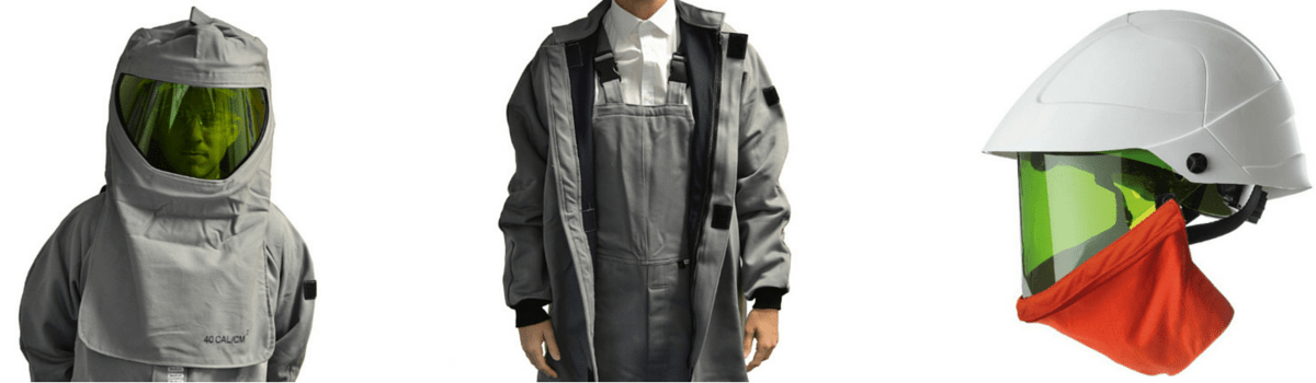
Arc flash clothing is essential to provide “head-to-toe” worker protection against arc incidents – this includes a complete range of arc flash gloves, arc flash helmets and garments for utility workers carrying out installation and maintenance tasks on LV MV HV underground cables, overhead lines and electrical substation equipment.
Cable jointers working on underground cables, linesmen stringing overhead conductors and SAP’s switching high voltage substations all confront daily dangers of electrocution which can only be moderated by a responsible attitude to electrical safety and risk assessment.
Nothing has changed. Serious injury, high degree burns, electrocution and all to commonly death are the dangers that face these workers daily if the proper electrical safety precautions are not taken.
Here, we take a look at 10 of the most important factors that need to be considered regarding LV-HV Electrical Safety.
The list below is by no means exhaustive, however it does cover 10 of the most pertinent points that must be considered prior to carrying out any electrical installation, maintenance or other work:
Arc Flash – calculation, risk assessment, protection and dangers
Electrical Accidents – causes, courses and cable faults
Electrical Isolation – what is lock-out tag-out?
Electrical Accidents – prevention and risk assessment
Arc Flash Protection – eliminating, reducing and quenching
British Standards – domestic electrical protection and BS7671
Dead or Live – energised or de-energised electrical working
Image: Jim McDonald (Owner/Live Line Training at Powerline Training Consultants)
1. Arc Flash
The most common hazards typically faced when working on LV HV electrical cables, switchgear and substation installations are electrical arcing (often called a ‘flashover’ or ‘arc flash’).
♦ Arc Flash Statistic: According to NFPA and IEEE from 1992 to 2002, over 2,000 workers a year or more than 5 workers a day were victims of an arc flash.
Arc flash can generate intense levels of heat and flames which can cause deep set burns and serious injury. The dangers of arc flash incidents are well documented and calculating the potential level and power of an electrical arc to provide adequate arc flash protective clothing can save lives should an arc flash incident occur.
We recently asked Hugh Hoagland (Partner at ArcWear & e-Hazard.com) and “leading-light” in arc flash protection to recommend the 3 most effective and reliable software packages for Calculating Arc Flash Risk & Hazard in accordance with NFPA 70E and IEEE 1584.
In addition to the intense heat, the levels of ultraviolet radiation from an electrical arc can also cause damage to the eyes. It is often the case that those working with or near electricity do not appreciate the risk of serious injury and consequential damage to equipment that can arise from arcing.
In the case of oil filled switchgear, burning oil and gas can be ejected causing serious injury or death to those nearby and major damage to buildings located in the vicinity of the arc flash blast. Switchgear that may be using SF6 gas as the insulating medium presents other risks that must be controlled and managed as the presence of F-gas is pervasive throughout industries.
These risks are managed effectively through the installation of an SF gas detector. The Crowcon F-Gasis a fixed point gas detector enclosed in an IP54 case and delivers reliable detection of freon gases (F-gases).
The F-Gas monitors levels of a range of refrigerant gases and also sulphur hexafluoride (SF6) and can be connected to any control system that can accept an analogue signal and is ideal for use in substations, switchgear, plant rooms, MV switches, ring main units, contactors and circuit breakers covering the electrical safety and gas detection requirements of the electrical distribution industry.
By providing SF gas detection, electrical safety is improved generally and the potential risks are managed.
Not only is damage to human life a real hazard, electrical fire and the subsequent damage to property and electrical infrastructure can cause considerable financial loss.
GIS Gas Insulated Switchgear 220kV. Image ABB
Adequate training and the lack of it is a continuing theme as a contributory cause of arc flash incidents and accidents….
Occupational Injuries From Electrical Shock and Arc Flash Events – extract from Final Report (2015) by The Fire Protection Research Foundation.
The Full Report is available as Slideshare download :
CATU, a world leader and respected voice in the world of electrical safety recommend the following 5 points to determine the selection of suitable arc flash clothing for protecting against arc flash :
Maximum fault current value
Phase/ground rated voltage at location of risk
Distance between the arc source and the reception source
AC cycle number and the mono or three-phase circuit type
Location of where the arc is produced (confined space)
This information enables an estimate of the arc flash risk level and determines the selection of arc flash clothing and PPE to use : 12 to 100 cal/cm³ or class 1 or 2. Arc flash site surveys and electrical risk assessments can be carried out by specialist service providers. For instance in the UK, ESUK is a specialist company concerned with the safe management of risk associated with LV-HV electrical work activities.
2. Electrical Accidents & Causes
The vast majority of electrical incidents occur because:
People are working on or near equipment that is either thought to be dead but is still live or,
By those working on equipment that is known to be live but they do not have the adequate training or are not using adequate protection equipment.
By not taking the required safety precautions and selecting the correct equipment for protection from the threats mentioned seriously increases the chances of an electrical incident occurring.
Here, we return again to the role of training and professionally educating electrical workers.
Investment both in terms of time and cash is required by responsible contractors to ensure the safety of their greatest asset, their workers.
Train and train some more. Training builds skills and confidence, it reinforces best working practises and should be encouraged throughout the lifetime of the career.
There is no shortage of training resources available, such as the High Voltage Training Courses for HV electrical engineers conducted by EA Technology’s Power Skills Centre.
Whether HV or LV, EA Technology are leading power engineering consultants and their courses and solutions are adopted by utilities across the globe.
Substations Courses
Specialist Courses
Cables Courses
Power Networks Courses
Protection Courses
Tailored Programmes
Pictured: The CableSniffer™ is designed to quickly and accurately detect cable faults. The CableSniffer™ pinpoints low voltage (LV) cable faults by “sniffing” the gases given off by faulting LV cables as the cable insulation burns. Widely used across UK DNO and global power utilities the EA Technology CableSniffer™ significantly reduces the impact of LV cable faults on customer minutes lost and restoration costs.
CableSniffer – Cable Fault Location For Low Voltage Cables
Quite simply, lock-out tag-out (LOTO) is the safety procedure of securely locking machines and equipment with numerous electrical safety padlocks to ensure that it cannot be energised without the necessary workers being present.
LOTO controls the flow of electrical energy and in practice is the isolation of power from the system by physically locking it in safe mode. In most cases, the safety switch has a series of holes through which a number of securing devices are fastened to ensure the switch cannot be turned.
Only the authorised individual is permitted to lock out and is the only one who can unlock the devices. LOTO is vital to to maintain worker safety while these systems are being operated when non-routine activities such as maintenance, repair, or set-up; or the removal of jams, clogs or misaligned feeds are performed.
Send an e-mail to [email protected] to request your FREE copy. Please include within the e-mail your name, ship to address, company and your job title.
4. Electrical Accident Prevention
There are many steps and precautions that should be taken in order to minimise the risk of electrical accidents occurring. Firstly, a risk assessment should always be carried out prior to any work starting and this should focus specifically on the electrical hazards present.
Secondly, the equipment used should be suitable for the application in which it is to be used. It must be properly designed, constructed, installed and maintained so that it does not present a risk of electric shock, burns or explosion.
Certified “explosion-proof” equipment must be used in areas that are classified as hazardous areas where flammable gases and vapours constitute potentially explosive atmospheres. Also where possible live work should be avoided during commissioning and fault finding. There must also always be adequate light, space and access to work safely.
The arc flash point is worth re-iterating and here is why.
According to OSHA, 80% of electrically related accidents and fatalities involving “Qualified Workers” are caused by arc flash / arc blast. Between 2007 and 2011, more than 2,880 fines were assessed for not meeting OSHA regulation 1910.132(d) which averages out to 1.5 fines a day.
As mentioned earlier, the electrical hazard dangers posed by an arc flash or electrical explosion can seriously injure or kill workers and also cause significant financial damage to infrastructure and cause significant downtime. If an electrical arc does occur, it is imperative that workers are already protected by wearing the correct clothing, whether that is insulating gloves, insulating matting, helmets and insulating boots or a full arc flash protection suit.
T&D Largest UK Stockist – CATU Electrical Safety Equipment
Apologies for further product placement, but leading manufacturers have innovated a series of electrical equipment geared towards eliminating, reducing or quenching arc flash.
Here are just 4 of them :
Eaton Arc Flash Reduction Maintenance System
A circuit breaker equipped with an Arc flash Reduction Maintenance System by Eaton can improve safety by providing a simple and reliable method to reduce fault clearing time. Work locations downstream of a circuit breaker with an Arc flash Reduction Maintenance System unit can have a significantly lower incident energy level. Read more.
ABB REA Arc Flash Detection System
Ultra-fast clearing of arc flash faults in medium voltage (MV) switchgear panels is essential in controlling arc flash hazards. Reducing the arcing time through faster detection is the most practical way of reducing incident energy levels and improving workplace safety. ABB’s innovative REA fast arc flash detection system uses fibre-optic sensors to cut the typical relay operating time to less than 2.5 ms – far faster than conventional relay technology. Read more.
Littelfuse Arc Flash Relays
Littelfuse AF0500 and PGR-8800 Arc-Flash Relays help improve safety and reduce equipment downtime in the event of an arc flash. Both relays use reliable light to send a trip signal to the breaker in 1ms to interrupt power before damage occurs. Their simple plug-and-play installation make them the perfect, cost-effective solution to lowering equipment incident energy (HRC). Read more.
Safe-T-Rack Remote Racking Systems
Safe-T-Rack® is an innovative, patented tool for circuit breaker remote racking and control. The product was specifically developed to provide users of low and medium voltage circuit breakers, including GE vertical lift (MagneBlast) designs and a variety of horizontally racked breakers, a comprehensive alternative to arc flash protection garments. Read more.
ABB 15 HK Circuit Breaker Remote Racking System
The video below demonstrates the need for effective arc flash protection as when it does occur, the results can be deadly.
Arc Flash
6. British Standards & BS7671
British Standards
According to UK Wiring Regulations, the main standard governing electrical installations is BS7671‘Requirements For Electrical Installations’.
This BS standard describes how electrical systems and equipment can be designed, conducted and installed in order for them to be used safely – to provide electrical safety in the workplace and in our homes.
Non compliant “BS7671” installations often feature a potentially lethal cocktail of manufacturers devices that may not have been tested as a completed unit – whilst this “pick and mix” attitude might be acceptable practice in Europe, it definitely does not comply with British Standards.
Earlier this year, we joined forces with Michael Halverson, owner of M-Spec Services Electrical Contractors, a respected UK based electrical contractor. We discussed the recent changes to the BS7671 Wiring Regulations and their affect on the selection and installation of Domestic Household Consumer Units.
“Shoddy cowboy builder charged £49,000 to turn our home into a deathtrap. One light switch turning on a bulb elsewhere in the home.” Via Daily Mail.
In addition, further guidance can be taken from three British Standards – BS6423, BS6626 and BS6867.
HSG230 Keeping Electrical Switchgear Safe includes guidance on the selection, use, care and maintenance of high voltage and low voltage switchgear.
When using electrical equipment in explosive atmospheres, certified products must be used and the Dangerous Substances and Explosive Atmospheres Regulations 2002 covers the regulations that should be followed for onshore installations.
For offshore applications, the Offshore Correct Selection & Use Of Equipment Electricity at Work : Safe Working Practices Page 8 of 33 Health & Safety Executive Installations (Prevention of Fire and Explosion, and Emergency Response) Regulations 1995 should be followed.
7. Partial Discharge & High Voltage Cable Breakdown
Partial Discharge Damage To Electrical Cable Insulation. Image HVPD
A Partial Discharge (PD) is an electrical discharge or spark that bridges a small portion of the insulation between two conducting electrodes.
Partial discharge is an electrical discharge or spark that bridges a small portion of the insulation between two conducting electrodes.
PD can occur at any point in the insulation system, where the electric field strength exceeds the breakdown strength of that portion of the insulating material.
Electrical failures of three phase HV switchgear are most likely to occur during, or shortly after, switchgear operation. The way switchgear is operated, its condition and the conditions in the electrical system at the time it operates will largely determine whether it will function safely.
The use of handheld partial discharge equipment can be considered for use as an additional safety measure during a routine inspection or when entering a substation. The use of partial discharge detection equipment can reduce the risks to people who perform inspections by providing a warning that something may be wrong.
HV electrical switchgear should not be used where its strength and capability may be exceeded unless there is no potential danger of anybody being exposed to the results. In order to prevent any future danger, switchgear and machines must be adequately maintained and details for guidance on the maintenance of HV electrical switchgear can be found in BS6626.
BS6626 is a British Standard which gives recommendations and guidance for the maintenance of electrical switchgear and controlgear having a rated a.c. or d.c. voltage above 1kV and up to and including 36kV.
Older switchgear may contain parts that were manufactured from asbestos or asbestos-containing materials (ACMs).
Getting it right first time. When electrical installations are commissioned and installed, the correct equipment must be used to not only prevent electrical explosions and arc flash but to also minimise the financial costs associated.
If any old equipment is still in use including old type switchboards and fuse-boards used by electricity distributors, then this is not designed to prevent people touching live conductors and suffering injuries from shock or burns.
Electrical equipment to be used in hazardous areas must be certified for use and have adequate certification.
Consideration must also be given to the environment in which the equipment is being used and whether there is any potential for an explosion or leak to occur.
Potentially explosive atmospheres are regulated under the ATEX Directive in Europe and geo-specific hazardous area classifications cover the rest of the world. Adverse external factors should be considered for the electrical equipment such as excess damp or humidity conditions.
The assessment of the working area must be carried out before work commences – given average travel distance from an oil rig to the nearest hospital (by helicopter) offshore locations consequently have extremely rigorous electrical safety working practises. We covered BP’s recently….
Assessing safe working electrical practices can be divided into four stages :
Deciding whether to work live or dead
Planning and preparations for actions that are common to both dead and live working
Procedures for working dead
Procedures for working live
This basic flow chart for assessing safe working practices helps to assess exactly what should be taken into consideration:
Selection chart for assessing safe working practices
The age of switchgear and other electronic equipment should be taken into account as the risk of catastrophic failure increases with age and a process of assessment should be carried out to decide on the appropriate action for dealing with aged switch-gear.
10. Should You Work Dead Or Live?
Working either live or dead is dependent upon the work being carried out and the equipment being worked upon. Working dead simply means working on or with electrical equipment of which the power source has been switched off. Working live means the opposite – the power is still on and the equipment is live.
Typically, normal policy is to work dead and deciding whether to work dead or live is extremely important. It is normal for utilities to recommend work on or near electrical apparatus to be on de-energised equipment, not live, i.e. isolated.
There are a series of questions and points to consider when deciding between working and working dead live:
Can the normal policy of dead working be carried out?
There are three conditions that must be met for live working to be considered acceptable over dead working. These are: It is unreasonable in all the circumstances for the conductor to be dead? It is reasonable in all the circumstances for the person to be at work on or near that conductor while it is live; and suitable precautions (including, where necessary, the provision of personal protective equipment) have been taken to prevent injury.
Is it unreasonable for the work to be done dead?
There are some circumstances in which it would be unreasonable to make the equipment dead due to the difficulties it would cause. Situations where it may not be technically feasible, a DNO needs to connect a new low-voltage service to an existing main or switching off a system, such as the supply to an electric railway track would cause excessive financial cost.
Identify, assess and evaluate the risks and methods for controlling them
If it has been decided that the work must be carried out live, then a risk assessment is required to evaluate the work on or near the specific equipment and it must be carried out by someone with comprehensive knowledge and experience of the type of work.
Decide whether it is reasonable to work live
The risk assessment should inform managers and supervisors whether it is safe to work live. At this stage the operational and economic factors of the work being live should be taken into consideration and evaluated against the risks of working live.
Decide whether suitable precautions can be taken to prevent injury
Providing the required points have been met, live work can still only be justified if suitable precautions are taken to prevent serious injury arising from the hazards noted in the risk assessment.
Arc Flash – HV Substation Switching
Thorne & Derrick are global distributors for the full range of CATU electrical safety products.
The range that ensures your worker safety and prevents and injury or serious harm occurring.
T&D distribute the most extensive range of LV, MV & HV Cable Jointing, Terminating, Pulling & Installation Equipment – we service UK and international clients working on underground cables, overhead lines, substations and electrical construction at LV, 11kV, 33kV and EHV transmission and distribution voltages.
Thorne & Derrick invite you to join LinkedIn’s largest LV-HV Electrical Discussion Group : Low & High Voltage Power, Cabling, Jointing & Electricals. Discussion subjects include cable installations, cable jointing, substation, overhead line and electrical construction at LV, 11kV, 33kV and EHV. Network, engage and promote your profile, company or products with over 10,000 influencers.
Request a Quote Call Us: +44 (0)191 410 4292 Stokbord cable protection covers are rigid HDPE protection boards designed to be installed above buried cables in trenches. They are manufactured and designed by Centriforce to provide strong mechanical protection...
Restoring transformer termination integrity with LoviSil When a major site recently experienced a fault on an 11kV transformer termination, the challenge was clear: restore the system quickly, safely and without the expense/disruption of full PILC cable replacement. Upon investigation,...


 working on medium and high voltage switchgear, switchboards, control panels and transformers.


 Atmospheres Regulations 2002 covers the regulations that should be followed for onshore installations.