Voltage Detectors Explained: Types, Uses & Safe Voltage Testing
Published 16 Nov 2026
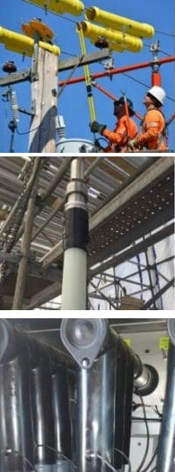
Voltage detectors are electrical safety instruments used to identify the presence or absence of voltage on electrical equipment and conductors. They are used by electricians, electrical engineers, utilities and maintenance teams working on low voltage (LV), medium voltage (MV) and high voltage (HV) systems.
Also known as voltage indicators or voltage testers, these devices are available in different configurations, including two-pole contact detectors, non-contact voltage indicators and specialist capacitive detectors for MV and HV power networks.
Although these instruments may perform similar functions, not every voltage detector is suitable for proving an electrical circuit dead. A non-contact voltage pen can indicate that an alternating electric field may be present, but it is not an acceptable substitute for the prescribed voltage testing procedure when verifying safe isolation.
In contrast, a suitable two-pole voltage indicator is commonly used for LV proving-dead procedures, while specialist MV/HV voltage detectors are selected according to the electrical system, rated voltage and approved operational safety rules.
This guide explains how voltage detectors work, the differences between contact and non-contact detection, relevant IEC standards and how to select appropriate instruments for electrical installations, substations and power distribution networks.
Thorne & Derrick supply a specialist range of voltage detectors, including MV voltage detectors and HV voltage detectors from manufacturers including PFISTERER and CATU.
Quick Answer: What Is a Voltage Detector?
A voltage detector is an electrical instrument designed to indicate whether voltage is present on a conductor or electrical system.
Depending on its design, the detector may use direct electrical contact, capacitive sensing or another approved detection principle to identify the presence of voltage.
Some instruments provide illuminated indicators, audible alarms or both. Others incorporate self-checking functions that confirm aspects of the device’s operational condition before use.
The principal types include:
- Two-pole voltage detectors: Contact devices commonly used in LV electrical testing and proving-dead procedures.
- Non-contact voltage indicators: Devices that detect the presence of an AC electric field without direct contact with a bare conductor.
- Capacitive MV/HV voltage detectors: Specialist contact instruments used on compatible power systems, switchgear and overhead lines.
- Fixed voltage detecting systems: Integrated arrangements fitted to specified MV/HV switchgear.
- DC voltage detectors: Instruments designed for particular direct-current systems, including railway applications.
The most important distinction is that voltage indication and verification of safe electrical isolation are not necessarily the same task.
How Do Voltage Detectors Work?
Voltage detectors identify electrical potential using a method appropriate to the type of system being tested.
The detection principle depends on whether the instrument is designed for low-voltage contact testing, non-contact AC indication or specialist high-voltage applications.
Contact Voltage Detection
A contact voltage detector uses purpose-designed electrodes or probes to establish an electrical sensing connection with the test points.
For a typical two-pole LV voltage indicator, the instrument detects the potential difference between two suitable points of an electrical system.
The detector then provides an indication according to its design and operating range.
Non-Contact Voltage Detection
A non-contact AC voltage indicator detects changes in the electric field surrounding an energised conductor.
This allows some indicators to respond through suitable insulation or an enclosure without direct contact with a bare conductor.
However, the indication can depend on distance, shielding, conductor arrangement, sensitivity and the electrical environment.
A non-contact detector failing to indicate voltage does not prove that equipment is dead.
Capacitive Detection on MV/HV Networks
Specialist capacitive voltage detectors use an approved sensing arrangement to detect alternating voltage on compatible medium- and high-voltage systems.
Portable detectors covered by IEC 61243-1 use contact with the appropriate bare part of the electrical system, together with the specified insulation arrangement.
This technology must not be confused with an ordinary handheld non-contact voltage pen.
What Do Audible and Visual Indicators Mean?
Many detectors provide light, sound or both to communicate the result of the test.
Some specialist models also indicate whether a self-test has passed or whether the instrument is ready for operation.
Colours, sounds and display states are model-specific. A green indicator, for example, must not be assumed to mean the same thing on every voltage detector.
What Are the Different Types of Voltage Detectors?
Voltage detection equipment is generally selected according to the electrical system, voltage range, testing method and applicable safety procedures.
Low Voltage Detectors
LV voltage detectors include two-pole contact indicators intended for use on electrical installations and equipment within their specified ranges.
They are used in appropriate electrical testing and safe isolation procedures, including checks on distribution boards and other LV systems.
Non-Contact Voltage Indicators
Non-contact detectors are portable instruments commonly used to identify a possible AC voltage presence without exposed-conductor contact.
They can offer a preliminary warning but are not a substitute for a suitable two-pole voltage indicator when proving an LV circuit dead.
Medium Voltage Detectors
MV voltage detectors are specialised devices used for compatible switchgear, overhead lines and other electrical distribution equipment.
Models intended for 11kV or 33kV operation must be selected according to their approved voltage ranges and contact arrangements.
High Voltage Detectors
HV detectors are designed for specified power transmission and distribution applications. They may be used in substations and on suitable overhead line systems with approved insulating equipment.
Depending on the model, they may provide acoustic and visual warnings and automatic operational checks.
DC & Railway Voltage Detectors
Direct-current electrical systems require detectors designed for the relevant DC voltage and application.
For example, PFISTERER offers specialist double-pole detector configurations for particular DC railway and traction power systems.
These must not be substituted with AC-only detectors.
Contact vs Non-Contact Voltage Detectors: What’s the Difference?
The main difference is how the instrument interacts with the electrical system and what its indication is intended to establish.
A contact detector uses specified electrodes or probes to test the relevant electrical points. A non-contact AC detector responds to an electric field without the same direct-contact arrangement.
Why Can Non-Contact Voltage Detectors Give Misleading Results?
A non-contact indicator may fail to respond where the electric field is attenuated, screened or otherwise unsuitable for the sensing method.
It may also produce an indication influenced by nearby energised conductors or other field effects.
These limitations mean that the device is useful as an indication aid but cannot independently verify safe isolation.
Two-Pole Voltage Detectors Explained
A two-pole voltage detector uses two test probes or contact points to determine whether a potential difference is present between the selected points.
These instruments are especially important for appropriate LV voltage testing.
Why Are Two-Pole Voltage Indicators Used for LV Testing?
Two-pole instruments permit tests between specified points of an electrical system rather than relying solely on the electric field around one conductor.
HSE guidance recommends a suitable proprietary test lamp or two-pole voltage detector when checking the presence or absence of voltage on LV systems.
The instrument must be suitable for the system’s voltage and measurement environment, and its operation must be verified as required by the testing procedure.
What Is a Voltage Proving Unit?
A proving unit is a device used to confirm that a compatible voltage indicator functions correctly.
For applicable LV proving-dead procedures, the indicator should be verified before and after checking the electrical system.
A proving unit helps identify certain instrument failures that could otherwise produce a misleading absence-of-voltage indication.
A proving unit is not itself evidence that the tested electrical circuit is isolated, nor does it replace required inspections, calibration or maintenance.
Capacitive MV/HV Voltage Detectors Explained
Capacitive MV and HV voltage detectors are specialist instruments designed for detecting alternating voltage on compatible power networks.
These detectors can be used in appropriate substation and overhead line applications when the model, operating range and insulating arrangements meet the approved requirements.
How Is a Capacitive HV Detector Different From a Voltage Pen?
A portable IEC 61243-1 capacitive detector is a specifically engineered contact-type instrument for higher-voltage AC systems.
It uses a defined contact electrode and an appropriate insulation arrangement, rather than relying on proximity sensing by a general-purpose voltage pen.
Both may involve electric-field effects, but their construction, applicable standards, operating procedures and safety roles are different.
PFISTERER KP-Test 5 Voltage Detectors
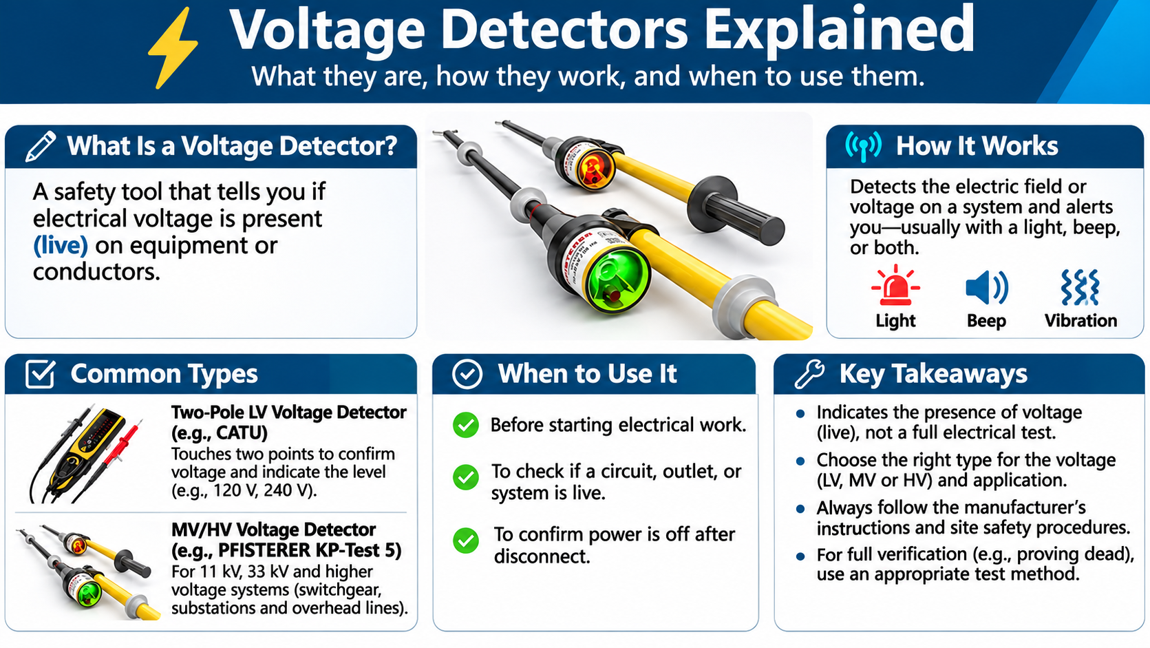
PFISTERER KP-Test 5 voltage detectors include models intended for selected MV/HV switchgear and overhead line applications.
The product family incorporates audible and visual indication together with operational self-testing features.
Different models are available for different nominal voltage ranges and contact arrangements.
View PFISTERER medium voltage detectors and high voltage detector configurations.
CATU High Voltage Detectors
CATU supplies specialist voltage detectors for power transmission and distribution applications, including compatible switchgear and overhead line systems.
Selected instruments incorporate visual and audible detection, dedicated contact electrodes and compatible insulating arrangements.
See the CATU IEC high voltage detector range for product-specific specifications.
Voltage Detectors for LV, 11kV, 33kV & HV Systems
The correct detector depends on the electrical system, voltage, current type, frequency and method of testing.
Equipment designed for one voltage system must not be assumed suitable for another.
Low Voltage Electrical Systems
LV applications include electrical distribution boards, industrial equipment and building electrical installations.
Suitable two-pole indicators are used in the prescribed voltage detection and proving-dead procedures.
11kV & 33kV Power Networks
MV systems may require specialist contact-type voltage detectors designed for the relevant AC voltage range and switchgear or overhead line arrangement.
Examples include selected PFISTERER KP-Test 5 and CATU detector models, subject to their specific approvals and instructions.
66kV, 132kV & Higher-Voltage Systems
HV networks require purpose-designed detection equipment, compatible insulating arrangements and authorised operational procedures.
The nominal voltage range is only one selection factor. Frequency, electrode arrangement, environmental suitability and the equipment being tested must also be checked.
DC Railway & Traction Systems
Railway systems may use AC overhead electrification or DC traction supplies, depending on the network.
Specialist detectors are selected for the relevant voltage, electrical configuration and prescribed railway safety rules.
Browse railway voltage detectors for appropriate AC and DC applications.
Voltage Detector vs Multimeter: What’s the Difference?
A voltage detector and a multimeter can both provide information about an electrical system, but they are designed for different purposes.
A voltage detector is principally intended to indicate the presence or absence of voltage within its specified function.
A multimeter is a measurement instrument that may provide numerical readings for voltage, resistance, current and other electrical quantities.
Why Isn’t a Multimeter the Preferred Instrument for Proving Dead?
Multimeters can have selectable modes, ranges and input connections. Incorrect settings or connections can lead to misleading results and dangerous situations.
HSE GS38 therefore recommends an appropriate test lamp or two-pole voltage detector when checking for the presence or absence of voltage on LV equipment, rather than a multimeter.
Multimeters remain useful for suitable measurement and diagnostic tasks carried out by competent personnel using appropriately rated equipment.
Can a Voltage Detector Prove an Electrical Circuit Dead?
A suitable voltage detector can form an essential part of an approved proving-dead procedure, but not every voltage detector is acceptable for this purpose.
The required instrument and procedure depend on the electrical system and applicable operating safety rules.
Proving Dead on Low Voltage Systems
For LV systems, the prescribed safe isolation procedure includes establishing that the correct circuit has been isolated, securing it against reconnection and testing for the absence of voltage using appropriate equipment.
A suitable two-pole voltage indicator or proprietary test lamp should be used and proved functional before and after testing in accordance with the applicable guidance.
All relevant conductors and possible sources of supply must be addressed under the approved procedure, including alternative or backfeed supplies where applicable.
Proving Dead on Medium & High Voltage Systems
MV and HV systems require authorised safety procedures appropriate to the network and equipment.
These may include isolation, securing against re-energisation, approved voltage testing, earthing and other measures specified by the responsible electrical authority.
Detector self-testing, appropriate contact electrodes, insulating equipment and approved operating ranges must be considered in accordance with the manufacturer’s instructions and operational safety rules.
Can You Prove Dead With a Non-Contact Voltage Pen?
No. A conventional non-contact voltage pen must not be relied on to prove an LV circuit dead.
Failure to indicate voltage may result from the sensing conditions rather than the actual absence of electrical energy.
Non-contact voltage pens should be treated as supplementary indicators where their use is appropriate, not substitutes for the prescribed proving-dead method.
Voltage Detector Standards: IEC 61243, GS38 & IEC 62271
Several standards and guidance documents apply to different voltage detection instruments and electrical systems.
It is important not to assume that all detectors are covered by the same standard.
What Does IEC 61243-3 Cover?
IEC 61243-3 addresses hand-held two-pole low-voltage detectors for specified AC and DC voltage ranges.
It covers equipment designed to make contact with electrical systems and sets relevant performance and safety requirements.
What Does IEC 61243-1 Cover?
IEC 61243-1 addresses specified portable capacitive voltage detectors for AC electrical systems exceeding 1kV.
Its requirements relate to particular contact-type voltage detection arrangements used on higher-voltage systems.
What About Fixed Voltage Detecting Systems?
IEC 62271-213 covers voltage detecting and indicating systems integrated into suitable HV switchgear.
This standard replaced earlier requirements covered by IEC 61243-5 and IEC 62271-206.
A fixed switchgear indication system must only be used for the functions and procedures approved for its design.
Why Is HSE GS38 Important?
HSE GS38 provides practical UK guidance on selecting and using electrical testing equipment for LV systems.
It addresses suitability, test leads, probes, installation categories, inspection and precautions when checking voltage presence or absence.
The applicable edition, manufacturer requirements and site safety procedures should be confirmed before equipment is specified or used.
How to Choose the Correct Voltage Detector
Selecting a voltage detector requires more than matching a product to a nominal system voltage.
The device must be suitable for the actual testing task, electrical environment, operating conditions and approved safety procedure.
1. Confirm the System Voltage
Determine the nominal voltage and possible operating conditions of the electrical system.
The instrument must be approved for the relevant detection range and system type.
2. Identify AC or DC Operation
Confirm whether the installation uses alternating or direct current.
An AC-only detector must not be assumed suitable for DC applications, and specialist traction or railway systems may require dedicated equipment.
3. Establish the Testing Purpose
Identify whether the task involves preliminary voltage indication, measuring voltage, an approved proving-dead procedure or a specialist MV/HV switching operation.
These tasks may require different instruments and procedures.
4. Check the Contact and Insulation Arrangement
For contact detectors, verify the required electrodes, probes, insulating poles and accessories.
The detector and insulation arrangement must be compatible with the system and approved working method.
5. Confirm Standards and Instrument Condition
Check the manufacturer’s documentation, applicable standards, inspection requirements and instrument condition.
Where relevant, confirm the appropriate installation measurement category, voltage rating, environmental limitations and functional test requirements.
6. Consider Environmental Conditions
Some detectors are designed for specific outdoor, humidity or weather conditions, while others are restricted to particular environments.
Do not assume all detectors can be used in rain, snow, contaminated areas or difficult electrical field conditions.
Common Voltage Detection Mistakes and Safety Risks
Using a Non-Contact Pen to Prove Dead
This is a critical error. A non-contact indicator may not detect voltage even where dangerous electrical energy remains present.
Using a Detector Outside Its Rated Range
A detector must be suitable for the operating voltage, current type and electrical system.
Using an unsuitable model can produce unreliable indications or expose personnel to danger.
Confusing a Self-Test with Confirmation of Isolation
A detector self-test can confirm specified aspects of instrument operation, but it does not establish that the electrical system has been correctly isolated.
Assuming All High Voltage Detectors Work the Same Way
Contact electrodes, voltage ranges, insulating arrangements, frequency requirements and indication methods vary by model.
Using Damaged or Unsuitable Accessories
Test leads, electrodes, poles and other components must be compatible, correctly rated and in a suitable condition.
Misinterpreting Indicator Colours
Visual and audible outputs must be interpreted according to the actual instrument instructions, not assumptions based on another device.
Failing to Consider Alternative Supplies
Backfeeds, standby generation, energy storage systems and other sources may create hazards if the isolation and voltage testing arrangements are incomplete.
Voltage Detectors from Thorne & Derrick
Thorne & Derrick supply specialist electrical safety and voltage detection equipment for distribution networks, substations, utilities, rail infrastructure and industrial electrical applications.
Our range includes instruments from established manufacturers including PFISTERER and CATU.
- Voltage Detectors – main range of MV and HV voltage detection equipment.
- CATU LV, MV & HV Voltage Detectors – product information covering different voltage detection applications.
- Medium Voltage Detectors – detector configurations for relevant 11kV and 33kV power networks.
- High Voltage Detectors – equipment for compatible substations and overhead line systems.
- CATU IEC High Voltage Detectors – specialist detector models for appropriate HV applications.
- Railway Voltage Detectors – equipment for selected AC and DC railway power systems.
For technical assistance selecting a suitable voltage detector, provide the system voltage, AC or DC characteristics, electrical equipment type, required testing function and applicable operational safety specification.
Voltage Detectors Frequently Asked Questions
Q: What is a voltage detector?
A: A voltage detector is an instrument designed to indicate the presence or absence of electrical voltage within its specified operating range and application.
Q: How does a voltage detector work?
A: A voltage detector responds to electrical potential using a suitable contact, capacitive or other approved detection principle. The detection method depends on the instrument design and electrical system.
Q: What is the difference between contact and non-contact voltage detectors?
A: Contact detectors use specified electrical test points or electrodes. Non-contact AC indicators detect an electric field without direct contact with a bare conductor. Their applications and safety limitations differ.
Q: Can a non-contact voltage detector prove a circuit dead?
A: No. A conventional non-contact voltage pen must not be relied on to prove an LV circuit dead. The prescribed safe isolation procedure requires appropriate voltage testing equipment and verification of its operation.
Q: Why use a two-pole voltage detector?
A: A suitable two-pole voltage detector checks the potential difference between specified test points. Such instruments are recommended for appropriate LV voltage detection and proving-dead procedures.
Q: Can a multimeter be used to prove dead?
A: HSE GS38 recommends a suitable proprietary test lamp or two-pole voltage detector for checking the presence or absence of voltage on LV equipment rather than a multimeter. Incorrect settings or connections can create risks.
Q: What is IEC 61243-1?
A: IEC 61243-1 covers specified portable capacitive voltage detectors for AC systems exceeding 1kV, including relevant contact-type instruments used on MV and HV networks.
Q: What is IEC 61243-3?
A: IEC 61243-3 covers hand-held two-pole low-voltage detectors within the AC and DC voltage ranges defined by the standard.
Q: Can the same detector be used for 11kV and 33kV systems?
A: Only where the particular detector is approved for both nominal voltage ranges and the relevant electrical equipment and testing conditions. Voltage range compatibility must be verified using the manufacturer’s documentation.
Q: Do voltage detectors work on DC systems?
A: Some detectors are specifically designed for DC electrical systems, including railway traction applications. An AC-only voltage detector must not be assumed suitable for DC use.
Q: What should I check before choosing a voltage detector?
A: Check nominal voltage, AC/DC operation, frequency, electrical equipment, detector type, applicable standards, contact and insulating arrangements, environmental conditions and the approved testing procedure.
Conclusion: Choosing the Right Voltage Detector
Voltage detectors are essential instruments for electrical voltage indication and, where appropriately specified, the verification of absence of voltage as part of an approved safety procedure.
Two-pole contact indicators, non-contact voltage pens, capacitive MV/HV detectors and specialist DC instruments use different methods and serve different purposes.
For LV installations, a suitable two-pole voltage indicator plays an important role in prescribed proving-dead procedures. For MV and HV systems, approved detectors and operating arrangements must be selected according to the network and equipment.
The correct detector is determined by the electrical application, not simply the highest voltage rating shown on the product. Compatibility, standards, test method, equipment condition and authorised safety rules are equally important.
Thorne & Derrick supply PFISTERER and CATU voltage detection equipment for electrical utilities, contractors, substations, rail infrastructure and industrial power systems.
Contact our technical sales team for support selecting voltage detection equipment appropriate to your specified electrical application.