

Commercial Scalable Fault Isolation By G&W Electric
Published 07 Jan 2021

Commercial Scalable Fault Isolation
G&W Electric
The following Case Study by G&W Electric and presented by Thorne & Derrick describes how a southern utility was interested in improving service reliability by installing an underground fault detection, isolation, and restoration scheme for a circuit feeding several important residential/ commercial customers.
Thorne & Derrick are Specialist Distributors of Substation, Electrical Safety, Cable Jointing & Accessories to UK and international utilities and contractors providing electrical power at distribution and transmission voltage levels.
Challenge
A southern utility was interested in improving service reliability by installing an underground fault detection, isolation, and restoration scheme for a circuit feeding several important residential/ commercial customers. They needed a solution that could be scalable from an individual switch to a full circuit of switches capable of performing an open loop restoration. A base loop would be installed first and new switches added as the funds became available.
Solution
G&W Electric worked with the utility to help design a system that was flexible enough to meet their current and future needs. The design concept was based around multi-way automated switches connected to each other in an open loop. Communication would be through fiber optic cable for the protection circuit and SCADA.
Four-way Trident®-SR solid dielectric switches were chosen for the load switching and fault interrupting. The Trident-SR was an ideal switching product for this solution due to the ease of automating it with any relay, innovative cycle speed operation, and multi-way mounting configurations. A front/back switch design was chosen due to its narrower footprint which would fit traditional air gear pads (see Images 1 and 2).
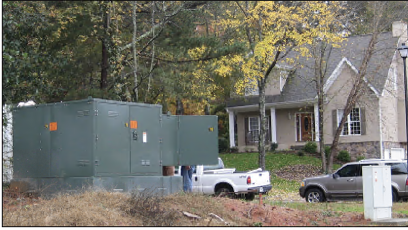
Image 1 Padmount switch with side control enclosure
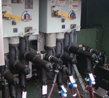
Image 2 Front or back access padmount
The two source ways of the Trident-SR switches were controlled and protected by SEL-451 relays. The two load ways were controlled and protected by SEL-751A feeder protection relays. G&W Electric designed and built the two relay panels in a common enclosure on the side of the switch. Both panels had 120 V outlets which allowed operators to plug in laptops when working on or near the switches (see Image 3).
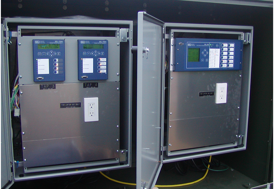
Image 3 SEL-751As and 451 were mounted in a common enclosure on the side of each switch.
The relay logic was designed to be extremely flexible so the same program could be used in multiple scenarios. This was accomplished using the extensive logic capability and multiple setting groups in the SEL-451 relay. The utility could choose whether to use the switch as a standard automatic transfer switch, as a through point automated loop switch where both
line ways are normally closed, or an open point automated loop switch where one line way is normally open.
When in the automated loop settings, each switch only communicated with the switches on either side of it. That meant there was no physical limit to the number of switches in the restoration circuit. This innovative control design allowed the utility to build their automation loops one switch at a time and add future switches as their budget permitted. It also provided a common switch design with single stock code which simplified future replacement requirements and training for their maintenance and installation crews.
The communication method for the protection circuit and SCADA system was single-mode fiber optic cable and SEL 2829 transceivers. This communication network was used to allow critical information to be passed between switches to automatically isolate faults and restore power in a minimal amount of time without having to dispatch crews.
This “smart switching” scheme is one of the most advanced technologies on the market and has been implemented by utilities worldwide who wish to provide the best service reliability to their customers.
When a fault is sensed, the relay trips the closest fault interrupter and disables the tripping of the other line way fault interrupter to maintain power to the loads. Next, a Mirrored Bits® signal is sent from the interrupting switch toward the open point. If the next switch in the line is closed, the signal will tell it to open to isolate the faulted line.
The signal is passed down the network from switch to switch until it encounters the open point. When the signal is received by the open point switch, it closes to restore power. This allows for an unlimited number of switches to be in the protective circuit and still maintain fast and effective isolation and restoration.
Conclusion
The scheme was tested and its operation witnessed by the customer at G&W Electric’s facility in Illinois. The initial phase has been installed and is up and running. It has inspired other utilities in the region to use a very similar scheme for their automated loops.
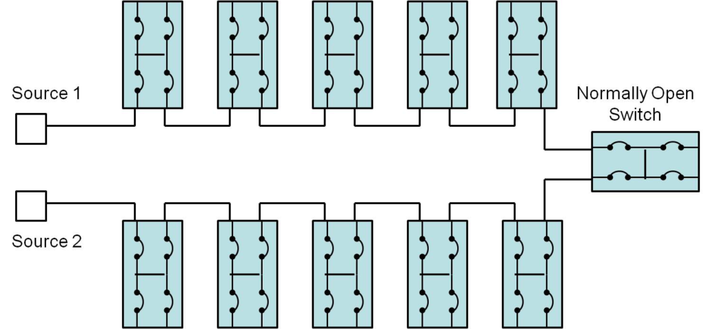
Figure 1 System Diagram
G&W ELECTRIC
Overview of G&W Cable Accessories

In 1905 G&W introduced the first disconnectable cable terminating device.
Over 100 years later, G&W continues to create technical innovations that have improved performance and reliability. With over 100 years experience, G&W is the name you can trust for quality cable accessories. With sales representation worldwide, G&W has a proven track record for success.
G&W cable accessories are designed to accommodate cables from all manufacturers and can be created to accommodate any customer cable system. The optional mechanical shrink feature offers an easier and faster installation while reducing possible damage during installation. G&W also offers installation supervision and installation training, which can be customized to suit the audience.
G&W offers a variety of transmission cable accessories for extruded dielectric cable systems. Cable terminations are available for outdoor applications to 230kV and include porcelain or composite insulator options and premolded designs. Gas insulated substation designs are available to 230kV.
Transition cable splices and cable joints are available to 138kV and include premolded designs. All cable terminations and cable joints incorporate built-in stress control and dielectric fluid. Dry type designs are also available for maximum ease of installation.

Substation, Electrical Safety, Cable Jointing & Accessories | 11kV 33kV 66kV to 400kV


