Cable Bending Radius Explained: Minimum Radius & Installation Risks
Published 15 Oct 2026

Cable bending radius is the minimum radius to which an electrical cable can be bent without risking damage to its construction or compromising its intended performance. It is an important consideration when installing LV, MV and HV power cables through underground ducts, trenches, substations, cable trays and other electrical infrastructure.
Every power cable has limitations on how tightly it can be bent. Exceeding these limits can damage the outer sheath, insulation, metallic screen, armour or conductor construction, potentially affecting the cable’s long-term electrical and mechanical reliability.
The correct minimum cable bending radius depends on several factors, including cable diameter, insulation type, conductor configuration, screening, armouring and whether the cable is being pulled into position or has already been installed.
For electrical contractors, utilities, cable jointers and infrastructure engineers, understanding cable bend radius calculations is essential when planning cable routes, selecting installation equipment and preventing damage during cable pulling operations.
Thorne & Derrick supply cable pulling and cable laying equipment for LV, MV and HV installations, including cable pulling equipment for ducts, cable drum jacks and specialist equipment used to support controlled cable installation.
Quick Answer: What Is Cable Bending Radius?
Cable bending radius is the smallest permitted radius of curvature when an electrical cable is bent. It is normally expressed as a multiple of the cable’s overall diameter, such as 10 × D, 12 × D or 15 × D, where D represents the cable diameter.
For example, if a cable has an overall diameter of 40mm and its specified minimum bending radius is 12 × D, the minimum radius is 480mm.
This means the cable must not be bent around a curve tighter than the stated minimum radius under the conditions for which that limit applies.
The required radius varies according to cable construction and installation conditions. In particular, a cable being pulled around a bend may require a larger radius than the same cable after installation, when it is no longer subjected to pulling tension.
What Is The Minimum Cable Bending Radius?
The minimum cable bending radius is the tightest permissible curve that a cable can follow without exceeding its specified mechanical limitations.
When a cable bends, materials on the outside of the curve experience elongation, while those towards the inside experience compression. The extent of these forces depends on the bending radius and the construction of the cable.
Power cables contain multiple layers, including conductors, insulation, screens, armour and protective sheaths. These components may respond differently to bending because of their materials, dimensions and arrangement.
A correctly specified bending radius helps protect the integrity of these cable components during installation and throughout their intended operating life.
Is Cable Bending Radius Measured From The Inside Or Centre?
The measurement reference must follow the definition used in the applicable cable specification. Cable bending radii are commonly expressed with reference to the inside of the cable bend, rather than the outside edge of the curved cable.
This distinction matters because measuring from the centreline or outside of a large cable can produce a different result.
For example, consider a cable with an overall diameter of 40mm and a required minimum inside bending radius of 480mm. The inner surface of the cable must follow a radius no smaller than 480mm; the centreline radius would be approximately 500mm.
Always confirm how the specified radius is defined before checking a cable route, former, roller assembly or duct bend.
Why Is Bend Radius Important?
Maintaining the correct radius helps reduce the risk of:
- Cable insulation damage caused by excessive mechanical deformation.
- Outer sheath damage including cracking, kinking and distortion.
- Metallic screen deformation affecting sensitive MV and HV cable layers.
- Conductor stress caused by forcing the cable around excessively tight bends.
- Installation problems at duct entries, corners, cable trays and jointing locations.
- Premature deterioration where damage introduced during installation affects long-term cable performance.
How To Calculate Cable Bending Radius
The basic cable bending radius calculation is straightforward once the applicable bending factor and overall cable diameter have been established.
R = K × D
R = Minimum bending radius (mm)
K = Specified bending factor
D = Overall cable diameter (mm)
The bending factor must be taken from the applicable cable specification or approved installation requirements. It must not be selected solely because a similar cable uses that factor.
Example: Calculating The Minimum Cable Bending Radius
Consider a hypothetical cable installation with the following values:
- Overall cable diameter: 40mm.
- Specified bending factor: 12 × D.
- Installation condition: The condition for which the 12 × D limit is approved.
The calculation is:
12 × 40mm = 480mm
Minimum permitted bending radius: 480mm.
This means the cable must follow a curve with a radius of at least 480mm, measured using the reference required by the applicable specification.
The example demonstrates the mathematical method only. It does not establish that 12 × D is suitable for every 40mm cable.
Cable Bending Radius Calculation Examples
These are illustrative arithmetic examples using hypothetical cable specifications. They are not universal installation limits or a substitute for the applicable cable requirements.
Does Cable Diameter Affect The Required Bend Radius?
Yes. Where the bending factor remains constant, a larger-diameter cable requires a proportionally larger minimum bend radius.
However, two cables with the same external diameter may still have different bending requirements because of their insulation, screen, armour, conductor arrangement and overall construction.
For this reason, cable diameter alone is not sufficient to specify the minimum radius.
Dynamic vs Static Cable Bending Radius
An important distinction in cable engineering is the difference between dynamic bending radius and static bending radius.
These describe different installation conditions and may have different permitted minimum values where specified for the cable system.
What Is Dynamic Cable Bending Radius?
Dynamic bending radius applies when a cable is moving during installation, such as when it is pulled through a duct, around a bend or along a trench.
The cable may be subjected to pulling tension and contact forces while following the curve. As a result, the permitted dynamic radius can be larger than the static radius.
Dynamic limits are particularly relevant for:
- Cable pulling around underground duct bends.
- Changing cable direction using corner rollers.
- Guiding cables from drums into trenches.
- Pulling MV and HV cables through substations or tunnels.
- Installing heavy cables through routes containing multiple bends.
What Is Static Cable Bending Radius?
Static bending radius applies to a cable after it has been installed, where a separate static limit is permitted and the cable is no longer subjected to installation pulling tension.
For certain MV cable systems, a smaller static radius may be permitted when positioning cables at joints or terminations, using carefully controlled bending arrangements.
A reduced static limit must not automatically be applied to cable pulling operations or other route sections where its use has not been approved.
How Does Cable Construction Affect Minimum Bending Radius?
Different power cable constructions have different mechanical characteristics. Consequently, their permitted bending radii can vary significantly.
The conductor material, insulation, cable screen, armour, metallic sheath and number of cores can all influence bending behaviour.
Single-Core vs Three-Core Cables
Single-core cables and three-core cables may have different permitted bending radii even when operating at the same nominal voltage.
Multi-core cable construction introduces additional considerations because the individual insulated cores are assembled within a common cable structure.
Neither configuration should be assumed to have a universally larger or smaller bend-radius requirement without checking the actual cable specification.
Armoured vs Unarmoured Cables
Armoured power cables contain metallic armour that provides mechanical protection, but the armour also affects cable flexibility and bending behaviour.
Unarmoured cables may have different bending limits because their construction and mechanical response differ.
The permitted radius must account for the complete cable design rather than simply whether armour is present.
XLPE & Other Cable Insulation Systems
XLPE-insulated power cables are widely used in LV, MV and HV electrical distribution systems.
Although XLPE provides suitable electrical and thermal properties for many power cable applications, it remains part of a layered cable construction that must be protected from excessive mechanical deformation.
Other insulation systems, including EPR and paper-insulated cable constructions, may have different flexibility and installation requirements.
The correct bending requirement must always be determined using the complete cable construction and relevant installation conditions.
11kV, 33kV & High Voltage Cable Bending Radius
11kV and 33kV power cables commonly contain multiple electrical insulation and screening layers that must remain intact throughout installation.
These layers help maintain the electrical performance of the cable system, making correct handling and bending particularly important.
For medium voltage installations, the permitted bending radius often depends on:
- Cable voltage rating and construction.
- Single-core or three-core configuration.
- Copper wire screen, lead sheath or other screening arrangement.
- Armoured or unarmoured construction.
- Cable overall diameter.
- Dynamic or static installation conditions.
What Is The Minimum Bending Radius For An 11kV Cable?
There is no single minimum radius that applies to every 11kV cable.
Different 11kV cable constructions may have different bending factors because of their insulation, screening, armour and core arrangements.
For example, selected MV cable designs may specify different radii for dynamic pulling and final installed positions. The values are dependent on the applicable cable standard and the approved cable design.
Engineers must use the actual cable specification rather than assuming that all 11kV cables can be installed using the same multiplier.
What Is The Minimum Bending Radius For A 33kV Cable?
As with 11kV cables, 33kV cable bending radius depends on the specific cable construction.
Single-core cables with copper wire screens, lead sheaths or alternative metallic screening systems may each have different permitted bending requirements.
These limitations must be considered when designing cable routes through substations, underground ducts, cable trenches and termination areas.
What About 66kV, 132kV & EHV Cables?
Higher-voltage cable installations introduce additional considerations involving cable weight, mechanical handling, insulation construction, jointing arrangements and installation forces.
For 66kV, 132kV and EHV cable systems, the bending radius should be established as part of the approved project-specific cable installation design.
Long pulling distances, multiple bends and high cable tensions may require larger installation radii than the minimum geometrical bending limit alone.
Thorne & Derrick supply LV, MV, HV and EHV cable pulling equipment for utility, substation and infrastructure cable installations.
What Happens If An Electrical Cable Is Bent Too Sharply?
When a cable is bent more tightly than permitted, excessive mechanical deformation may affect one or more layers of its construction.
Some damage may be immediately visible, while other defects may not become apparent until testing, commissioning or later operation.
Outer Sheath Damage
Excessive bending can cause the protective cable sheath to stretch, compress, kink or become distorted.
Depending on the cable material and installation conditions, this may lead to cracks or other defects that reduce environmental protection.
Cable Insulation Damage
Electrical insulation must maintain its integrity throughout the cable’s operating life.
Excessive mechanical deformation may create defects or weaknesses in susceptible insulation systems, potentially reducing their long-term performance.
Metallic Screen & Armour Deformation
MV and HV cable constructions often include metallic screens and other protective layers.
Excessive bending can deform or damage these components, particularly where the cable is forced around a tight curve or subjected to high installation forces.
Conductor & Core Distortion
Sharp bending may impose excessive mechanical stress on conductors and the assembled cable cores.
This is particularly relevant to large power cables that are difficult to handle and require controlled pulling arrangements.
Potential Long-Term Electrical Failure
Mechanical damage introduced during installation may compromise cable integrity and contribute to deterioration under subsequent electrical, thermal or environmental stresses.
However, exceeding a bend-radius limit does not automatically establish that insulation breakdown or future failure will occur. The actual consequences depend on the cable design, extent of deformation and resulting damage.
Cable Bending Radius During Cable Pulling
Maintaining the correct bending radius is particularly important when cables are pulled through ducts, trenches, tunnels or other cable routes.
During a cable pull, the cable may experience both longitudinal pulling tension and contact pressure where it changes direction.
The combination of these forces can affect the mechanical loading on the cable at bends.
What Is Sidewall Pressure?
Sidewall pressure, also described as sidewall bearing pressure, is the contact loading experienced by a cable as pulling tension forces it against a curved support or duct surface.
For a given pulling tension, a tighter bend can increase the loading associated with that change in direction.
Therefore, a bend that satisfies the cable’s geometric minimum bending radius may still require further assessment when significant pulling tension is involved.
For controlled engineering calculations, cable installation specialists assess pulling forces, route geometry, friction and allowable sidewall pressure together.
How Can Cable Pulling Equipment Help?
Correctly selected installation equipment helps guide the cable along the intended route and reduce uncontrolled bending.
This may include:
- Cable rollers – support the cable along straight routes and guide movement through suitable curved sections.
- Corner rollers – help control direction changes where the roller arrangement provides the required radius.
- Cable drum jacks – support stable drum rotation and controlled cable payout.
- Cable pulling winches – provide controlled pulling force where mechanical assistance is required.
- Duct entry guides – help protect the cable from sharp edges and inappropriate changes of direction.
- Cable lubricants – reduce friction in suitable duct-pulling applications.
The equipment must be selected and arranged to suit the cable diameter, weight, installation route and specified mechanical limits.
For a broader explanation of the cable installation process, see our guide to cable pulling for LV, MV and HV power cables.
Cable Bending Radius In Ducts, Trenches & Substations
The location of a cable bend can influence the mechanical forces experienced during installation.
Common locations requiring particular attention include underground duct bends, trench corners, cable pit entries, substation cable routes and jointing or termination areas.
Underground Cable Ducts
When a cable is pulled through a duct, the curvature of the duct must accommodate the cable’s permitted dynamic bending radius.
Sharp duct bends can increase installation resistance and may create excessive mechanical loading, particularly where pulling tension is high.
Route design should consider both cable bending limits and the additional installation forces generated by bends.
Cable Trenches & Open Excavations
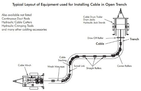
In open-trench installations, cable rollers and suitable guiding arrangements can help maintain controlled curvature as the cable changes direction.
Rollers must be positioned to form an acceptable cable path rather than allowing the cable to kink between isolated supports.
Substation Cable Routes
Substation cable routes may contain restricted spaces, vertical transitions, cable trenches and areas where cables need to approach jointing or terminating equipment.
These arrangements require careful consideration of cable curvature, mechanical support and the distinction between installation and final-position bending limits.
Jointing & Termination Locations
Where a cable must be positioned for a joint or termination, the final installed bending radius may differ from the dynamic installation requirement if a separate static limit is approved.
Controlled bending using suitable formers or supports may be required for certain cable systems.
A static allowance should only be used where permitted by the applicable cable and jointing requirements.
What Equipment Helps Maintain The Correct Cable Bending Radius?
Specialist cable installation equipment supports controlled cable movement and helps reduce the risk of excessive bending during installation.
Equipment selection should be based on the route geometry, cable construction, cable weight, pulling loads and required bending radius.
Cable Rollers & Corner Rollers
Cable rollers support power cables during installation, while suitable corner roller assemblies help guide cables through changes in direction.
The roller layout must provide sufficient curvature for the installed cable. A single small roller does not automatically provide a safe bend for a large-diameter power cable.
Cable Drum Jacks
Cable drum jacks lift and support cable drums so that cables can be paid out under controlled conditions.
Correct drum positioning can reduce abrupt changes in cable direction between the drum and the route entrance.
Cable Pulling Winches
Mechanical cable pulling winches are used where pulling force must be applied in a controlled manner.
Pulling operations should be planned so that the applied tension, cable bending radius and sidewall pressure remain within the applicable limits.
Duct Entry Guides & Cable Protection
Suitable entry guides and protective arrangements help prevent cables from contacting sharp duct edges or following an excessively tight curve as they enter or leave underground ducting.
Explore Thorne & Derrick’s cable pulling equipment for duct installations for related cable handling and installation products.
Common Cable Bending Radius Mistakes
Incorrect bending radius assumptions can create preventable risks during power cable installation.
Common mistakes include:
- Using one bending factor for every cable – different constructions require different approved limits.
- Confusing cable diameter with bending radius – the permitted radius is calculated using the correct multiplier.
- Applying static limits during pulling – a smaller final-position radius may not be permissible while the cable is moving under tension.
- Ignoring sidewall pressure – acceptable geometry alone does not establish that a pull is mechanically safe.
- Forcing cables around sharp corners – uncontrolled handling can damage cable layers.
- Using poorly positioned rollers – individual rollers may create localised tight bends rather than a smooth route.
- Overlooking installation temperature – cable handling requirements may change with temperature and material characteristics.
- Ignoring the actual cable construction – voltage and conductor size alone do not determine the correct bending radius.
These issues can affect installation quality even when the cable initially appears undamaged.
Cable Bending Radius Installation Checklist
Before installing an LV, MV or HV power cable, engineers and contractors should confirm the cable’s mechanical limits and planned route geometry.
For critical MV, HV and EHV cable systems, cable installation methods and route calculations should form part of the approved engineering design and installation plan.
Related Cable Pulling & Installation Equipment
Maintaining the correct minimum cable bending radius is one part of a properly planned cable installation.
Correct drum handling, cable support, pulling equipment and route preparation also contribute to controlled installation practices.
Thorne & Derrick supply specialist products for contractors installing LV, MV, HV and EHV cables into underground ducts, trenches, tunnels, substations and other cable routes.
- Cable Pulling & Cable Laying Equipment – equipment for installing power cables through ducts, trenches and infrastructure routes.
- Cable Pulling Equipment For Ducts – products used in underground cable duct installation, preparation and pulling operations.
- Cable Drum Jacks – hydraulic and screw-type equipment for supporting and handling LV, MV and HV cable drums.
- Manhole Cable Rollers – cable guidance equipment for duct, pit and manhole entry applications.
- Cable Pulling Winches – mechanical pulling equipment for suitable power cable installation applications.
- Cable Pulling Explained – a wider technical overview of cable installation methods, equipment and planning considerations.
Correct product selection depends on the cable construction, weight, overall diameter, pulling requirements and site conditions.
Cable Bending Radius FAQs
Q: What is the minimum bending radius of a cable?
A: The minimum cable bending radius is the smallest permitted radius of curvature under the applicable installation conditions. It is normally expressed as a multiple of the overall cable diameter, but the exact factor depends on cable construction and the relevant requirements.
Q: How do you calculate cable bending radius?
A: Multiply the cable’s overall diameter by its specified bending factor. For example, a 40mm cable with an approved minimum bending factor of 12 × D requires a minimum radius of 480mm for the applicable installation condition.
Q: What is the difference between dynamic and static bending radius?
A: Dynamic bending radius applies while the cable is moving during installation, potentially under pulling tension. Static bending radius applies after installation where a separate final-position limit is permitted. The dynamic limit may require a larger radius.
Q: What is the minimum bending radius for an 11kV cable?
A: There is no universal bending radius for every 11kV cable. The correct value depends on overall diameter, core configuration, insulation, metallic screening, armour and whether the cable is being pulled or positioned after installation.
Q: Can bending a cable too sharply damage the insulation?
A: Yes. Excessive bending can introduce mechanical deformation and potentially damage susceptible insulation layers. It may also affect the sheath, screens, armour or conductor arrangement. The consequences depend on the cable design and severity of the bend.
Q: Is the cable bending radius the same during pulling and after installation?
A: Not necessarily. Some cable designs specify separate dynamic and static bending radii. A smaller final-position radius must not automatically be used during cable pulling, because pulling tension and contact pressure introduce additional mechanical loading.
Q: What equipment helps prevent excessive cable bending?
A: Correctly selected cable rollers, corner roller assemblies, duct entry guides, cable drum jacks and controlled pulling equipment help guide cables through installation routes. Their arrangement must suit the required radius and permissible cable loading.
Q: Does a larger cable require a larger bending radius?
A: Where the bending factor is the same, a larger overall diameter produces a larger minimum bending radius. However, cables with the same diameter may have different permitted factors because of their construction, so diameter alone is not sufficient for specification.
Conclusion
Cable bending radius is a fundamental consideration when installing LV, MV and HV power cables. Every cable has mechanical limitations that must be respected to protect its conductor, insulation, screening, armour and protective sheath.
The correct minimum cable bending radius depends on the cable’s overall diameter, construction and installation conditions. Engineers must also distinguish between dynamic and static requirements and consider the additional forces experienced during cable pulling.
Excessively tight bends can introduce mechanical damage, affect cable performance and increase the risk of long-term deterioration. Correct route design, suitable installation equipment and controlled handling help reduce these risks.
Thorne & Derrick supply cable rollers, cable drum jacks, cable pulling winches and specialist cable installation equipment to support electrical contractors, utilities and infrastructure projects involving LV, 11kV, 33kV and higher-voltage cable systems.