Electrify The Future | Can Aluminium Really Beat Copper In Underground Power Cables?
Published 04 Aug 2021
Underground power cables are playing an increasingly important role in the electrification of the world. The excellent conductivity of copper makes it appear the natural choice for the conductor material. But that isn’t always the case. Experience with France’s transmission grid has shown that aluminium can sometimes prove to be the superior option when a comprehensive life cycle assessment (LCA) is carried out.
Frédéric Lesur, Senior Engineer for high voltage cable systems and power grids, explains.
There are many criteria that must be considered when selecting the conductor for an underground cable system. These include electrical considerations, thermal design, installation techniques, mechanical stresses and so on.
And of course, cost is an important factor, not just the purchase cost but the overall cost of operating the cable throughout its life. Environmental impact is also an increasingly important factor at the earliest stage of the cable design.
Electrical resistance
For underground cables, only two metals are used: copper (Cu) and aluminium (Al), due to their excellent conductivity. The best metal for conducting electricity is actually silver. Unexpectedly, gold comes in at third place – behind copper, while aluminium is fourth.
Copper has much better electrical conductivity than aluminium – by a factor of 1.64.
But it is over three times heavier and much more expensive. Copper prices can fluctuate considerably, but there have been times this century when the cost of copper has been five times that of aluminium.
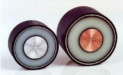
Figure 1 – Extruded XLPE cables with aluminium and copper conductors
What these factors mean is that while an aluminium conductor must be bigger to carry the same current as copper, the aluminium cable can be more cost-effective to purchase and easier to handle.
There are a few variations such as enamelled copper wires (CUE) or oxidized aluminium wires.
Experience in the French grid
As a concrete example, Figure 2 illustrates cable ratings calculated according to the IEC 60287 standard for different types and sizes of conductor. This is based on a typical French installation in a semi-urban area, with the cables laid in PVC ducts embedded in concrete with a trefoil geometry.
It is interesting to note the relative performance of the conductors. In one example, a 2500sqmm Al cable has very close to the same rating as a 2000sqmm Cu cable.
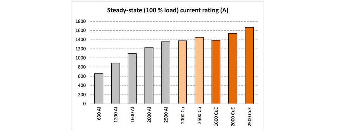
Figure 2 – Current ratings of conductors installed in France. The figures on the x-axis indicate the conductor cross-section eg 2000sqmm
Losses caused by conductors
Losses in the conductor account for the major proportion of the energy lost in an underground cable. Figure 3 shows the typical total losses for cables installed in France as a function of their current rating. The curves end at the steady-state permissible current rating, associated with the maximum temperature of the insulation material (90°C for XLPE = cross-linked polyethylene). The order of magnitude is 30 W/m per cable.
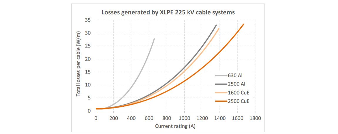
Figure 3 – Total losses dissipated per cable type and size (W/m)
Réseau de Transport d’Electricité (RTE), the French transmission system operator (TSO) has produced statistics showing that underground cable systems operate more than 95% of the time at a current rating lower than 60% of their maximum rating. This means that the losses are normally well under their maximum value. The remaining 5% of the operating time matches with the peak values and most constraining conditions, such as in a severe winter period with extensive use of electrical heating.
The conclusion is that an underground cable is therefore operated generally in conditions leading to “acceptable” losses. This point is essential, considering that power losses dominate the cable’s environmental impact. The closer to the maximum point the cable is operated, then the greater the environmental footprint and the higher the operational cost.
Economical design of cable conductors
When designing a cable system the aim is to stay within the current rating dictated by thermal behaviour. Effectively, the cable is designed not to exceed the maximum temperature of the insulating layer in any operational mode. Most of the time, the design engineer will select the size of conductor that allows the required operating temperature while staying on the safe side within a wide range of standardized sizes.
Until recently, this approach was regarded as offering the lowest investment cost. However, the global cost of a power link also depends on the actual cost of the energy losses. A bigger conductor, although more expensive on initial purchase, may generate lower losses than the thermally designed conductor. Therefore, it can become significantly more cost-effective after a few decades.
This approach is explored in Figure 4 that looks at the case for a cable system carrying 700 A.
Data is plotted on the graph as a function of the conductor size (two colours are used for Al and Cu conductors) and the investment cost of the installed system. The investment cost is made up of the actual cost of the losses at the specified current rating and the total cost.
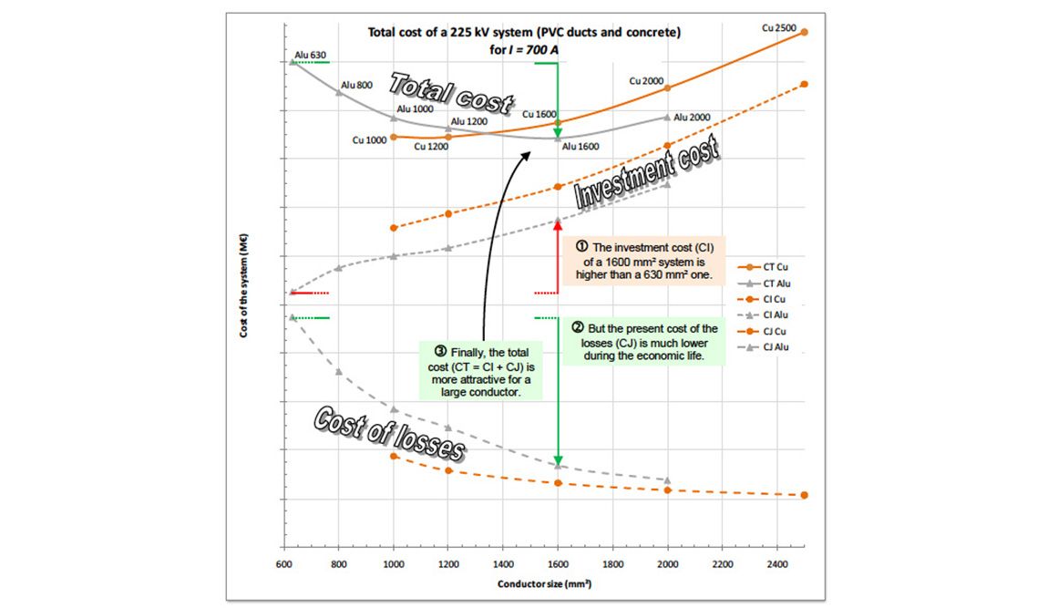
Figure 4 – Investment cost + actual cost of losses = total cost during the economic life of the cable
The investment costs increase with the conductor size, while the cost of losses decreases as there is less electrical resistance. The combination of both trends leads to U-shaped curves with an optimal conductor size. In the example, 1600sqmm Al is the most cost-effective conductor to transmit 700 A over a project life of 50 years. Yet, 630sqmm Al would have been selected from a strict thermal design point of view.
This optimisation is not only of an economic nature. The lower losses also play a favourable role in terms of environmental impact. The benefits can include less risk of thermal aging, reduced risk of thermal runaway due to uncontrolled soil drying, a larger safety margin to handle load peaks or unexpected hot spots, margins for overloads, etc.
Furthermore, lower losses help in limiting global warming.
The prospects for very large aluminium conductors
While maximum standardised cross-sections of conductors have moved from 1600 to 2500sqmm within recent years, some manufacturers are now offering new solutions with aluminium conductors of 3000sqmm or 4000sqmm, pushing the present limits of copper conductors.
Studies have been carried out to assess the interest in these huge components in terms of performance, installation, economics and environmental impact. They show that, for a given current rating, a cable with a very large aluminium conductor generates less energy losses than a cable with a smaller copper conductor of one or two sections.
The lower investment cost of the resulting aluminium cables could bring significant savings, despite the increased cost of installation (excavation, cable laying, assembly of joints, etc.). Design engineers then have to balance the attractive global cost with a number of additional constraints.
These include increased civil works, more rigid conductors and lower strength to resist pulling during installation, increased size of drums or lower delivery length on site, which means shorter sections and more cable joints. A larger conductor diameter also involves accessories of bigger size.
Perhaps the most significant barrier is that there is currently no experience in terms of the qualification of such huge cable systems.
Utilities and manufacturers will need to collaborate to address this challenge. However, at the conductor sizes used today there is substantial practical experience showing clearly that aluminium represents an important alternative to copper.
Thorne & Derrick
Nexans Main UK Stockist & Distributor
Contact us for Competitive Prices & Fast Delivery from Stocks for Heat Shrink, Cold Shrink & EPDM Rubber Connectors, Joints & Terminations up to 66kV.
Thorne & Derrick International are specialist distributors of LV, MV & HV Cable Accessories, Jointing, Substation & Electrical Equipment – servicing UK and global businesses involved in cable installations, jointing, substation, overhead line and electrical construction at LV, 11kV, 33kV, 66kV and EHV.
Stocking & Supplying | Duct Seals | Cable Cleats | Cable Glands | Electrical Safety | Arc Flash Protection | Jointing Tools | Cable Pulling Eqpt | Earthing & Lightning Protection | Feeder Pillars | Cable Joints LV | Joints & Terminations MV HV


Euromold MV HV | Cable Terminations, Connectors, Elbows & Joints


