Transformer Switching | Mitigating Inrush Currents During Transformer Energisation
Published 16 Sep 2019

➡ The following article has been prepared by Tim Rastall from Enspec Power
“As a Senior Electrical Engineer specialising in Grid Code Compliance and power quality solutions, I help wind, solar, energy storage and industrial connections comply with required standards and operate in an efficient and cost-effective manner.
At Enspec Power we specialise in the design, manufacture, installation and maintenance of Grid Code Compliance solutions and as such are able offer a bespoke and turnkey solution for any connection.
If you would like to find out more about our innovative solutions or how we could help you, please call me on 07481818740 or email me at [email protected].”
SynchroTeq – Transformer Switching
This report was produced by Enspec Power Ltd, it details the application of the SynchroTeq device for transformer switching. The document outlines the application and theory of controlled transformer switching and then presents two commissioned and operational site examples, one from a UK Solar Farm and another from a Wind Farm in Scotland.
In conclusion, the document demonstrates how the SynchroTeq can mitigate inrush currents during the energisation of transformers and provide site compliance with the P28 limit of 3%.
Introduction
When a transformer is energised it may draw a large transient current from the supply connection point. This large current draw results in a voltage dip. According to the UK standards (Electricity Council’s Engineering Recommendation P28), this voltage dip cannot exceed a specified amplitude and/ or duration. Due to this, it has been common practice to install a Pre-insertion Resistor (PIR), that is placed in the circuit during the transformer energisation to reduce the inrush current and thus voltage dip.
However, a PIR requires an extra circuit breaker, has a significant footprint and can be expensive. The SynchroTeq is a controlled switching device that can provide equal or better inrush mitigation to that of a PIR without the need for an extra breaker or costly install.
This document will cover the theory, installation and performance of the SynchroTeq when applied to transformer switching and will end by presenting two operational SynchroTeq installations.
Transformer Controlled Switching
When a transformer is de-energised, the magnetic core will contain a certain amount of residual magnetic flux. This residual flux is dependent on the voltage across the transformer at the time of de-energisation and can intensify saturation leading to high transient inrush current on re-energisation. The possibility or magnitude of saturation and thus inrush current is dependent on the point of re-energisation (angle) in relation to this residual flux. This effect can be seen graphically in Figure 2-1 below.
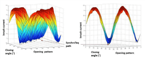
Figure 2-1 – Inrush Current due to Opening and Subsequent Closing Angle
The above Figure 2-1 shows the inrush current obtained across all possible closing angles for each possible opening angle. As can be seen, there is a best and worst-case closing angle for each opening angle. When switching a standard transformer arrangement there is an equal possibility of hitting a bad point as a good point, and thus a possibility of high inrush current. The SynchroTeq works by monitoring and calculating this residual flux, with knowledge of the residual flux it can calculate the optimum closing angle. This is seen graphically in Figure 2-1 above as ‘SynchroTeq path’.
The SynchroTeq then becomes an interface between the open/ close commands (manual, remote or protection) and the Circuit Breaker. Using the calculated residual flux and knowledge of the Circuit Breaker operation time, the SynchroTeq can target this optimum closing angle, thus mitigating high inrush currents. This process can be seen graphically in Figure 2-2 below.
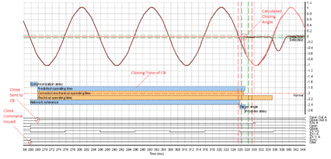
Figure 2-2 – SynchroTeq Controlled Close Operation (Phase A)
The above Figure 2-2 shows a closing operation carried out via the SynchroTeq (Phase A). In this example, the calculated closing angle, based upon the calculated residual flux, is around 220 degrees. Firstly, the close command for the CB is issued to the SynchroTeq, the SynchroTeq then waits until the target angle is the CB closing time ahead (predicted operating time), and then the close command is sent to the CB. The result here is the CB closing at the desired angle with minimum inrush current.
The SynchroTeq can mitigate inrush current using any modern CB. The CB can be a 3-pole gang operated device or a 3-pole individual pole device. When operating via a 3-pole gang operated device, the SynchroTeq cannot close the CB at the optimum point for each phase, in this instance, it calculates the optimum point for all three phases to keep inrush current to a minimum. When operating via an individual pole device inrush current can be completely avoided for unloaded transformers.
SynchroTeq Application
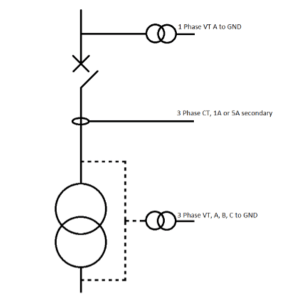
Figure 3-1 – SynchroTeq Signal Requirements
The above Figure 3-1 shows the signal requirements for transformer switching with a SynchroTeq device. The single-phase VT is used for voltage synchronisation, the CT’s are used to measure inrush current and the three-phase VT allows the SynchroTeq to calculate residual flux. The SynchroTeq then forms an interface between the circuit breaker open/ close commands and the circuit breaker itself.
Actual Application and Results
UK Solar Farm
The following results are for a SynchroTeq MVX installed on a UK solar farm.
The SynchroTeq was used to control the simultaneous energisation of the sites 2MVA and 1.77MVA 11/04kV transformers. A diagram of the site layout can be seen below in Figure 4-1.
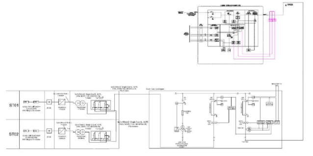
Figure 4-1 – Site SLD
The SynchroTeq MVX was mounted in the client substation and controlled the energisation of the main CB. The initial P28 studies for the site highlighted a 50th percentile voltage dip of 8.2% for the simultaneous energisation of the sites transformers, this can be seen below in Figure 4-2.
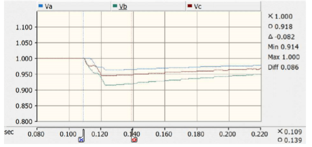
Figure 4-2 – PCC Voltage Dip for Whole Site Energisation
The DNO for this site stipulated a maximum voltage dip at the PCC of 6% due to the whole site energisation. The below Figure 4-3 shows the result of the SynchroTeq MVX commissioning:
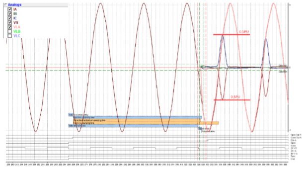
Figure 4-3 – Commissioned SynchroTeq Inrush Current
As can be seen from the above figure the resultant inrush current was 0.51PU (101A).
This resultant inrush current was then used to obtain a new voltage dip using the original P28 simulation model.
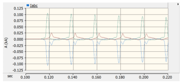
Figure 4-4 – SynchroTeq Resultant Inrush Current in P28 Model
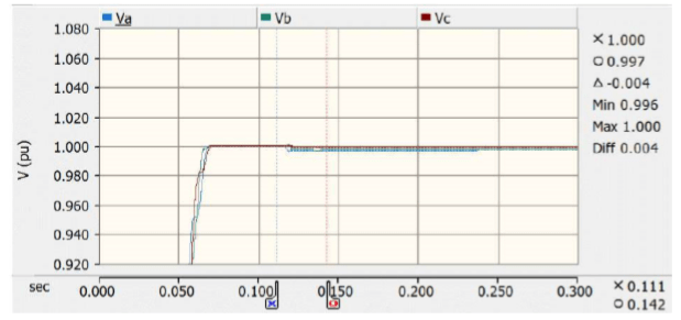
Figure 4-5 – Simulated Voltage Dip Based on SynchroTeq Inrush Current
As can be seen from the above figures, simulation of the resultant inrush current led to a PCC voltage dip of 0.4%. As the switching is now controlled by the SynchroTeq this level of inrush current will result from every future energisation, making the site fully P28 compliant.
Scottish Wind Farm
The following results are for a SynchroTeq Plus installed on a Scottish Wind farm. The SynchroTeq was used to control the energisation of the sites 90 MVA 132/33kV transformer. Figure 4-6 below shows the layout of the site.
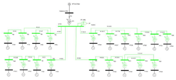
Figure 4-6 – Site SLD
The SynchroTeq Plus was mounted in the 132kV control room and controlled the energisation of the main 132kV CB. The initial P28 studies for the site highlighted a maximum voltage dip of 17.9% for the energisation of the sites transformer, this can be seen below in Figure 4-7.
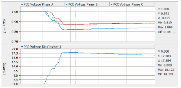
Figure 4-7 – PCC Voltage Dip for 90MVA Transformer Energisation
The DNO for this site stipulated a maximum voltage dip at the PCC of 6% due to the transformer energisation. The below Figure 4-8 shows the result of the SynchroTeq Plus commissioning.
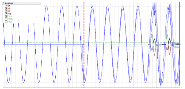
Figure 4-8 – Commissioned SynchroTeq Inrush Current
As can be seen from the above figure the resultant inrush current was 0.3PU (118A). A fast-acting voltage recorder was also connected to the 132kV VT and the recording during this switching event can be seen below in Figure 4-9.
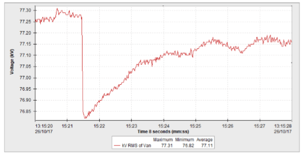
Figure 4-9 – Recorded Voltage Dip During SynchroTeq Energisation
As can be seen from the above figures, after commissioning of the SynchroTeq the obtained PCC voltage dip was 0.63%. As the switching is now controlled by the SynchroTeq this level of inrush current will result from every future energisation, making the site fully P28 compliant.
Conclusion

In summary, it has been shown that by using the SynchroTeq device, inrush current caused by transformer energisation can be significantly reduced. Two installed and commissioned cases have been presented that show the potential of the SynchroTeq to ensure P28 compliance when initial system studies predict potential for large voltage dips.
See how Thorne and Derrick support the Wind and Solar industries.
THORNE & DERRICK
Thorne & Derrick are national distributors of LV, MV & HV Cable Installation, Jointing, Substation & Electrical Equipment – servicing businesses involved in cabling, jointing, substation, earthing, overhead line and electrical construction at LV, 11kV, 33kV, 66kV and EHV. Supplying a complete range of power cable accessories to support the installation and maintenance of low/medium and high voltage power systems:
- Slip-on Cable Terminations
- Cold-shrink Cable Terminations
- Heat-shrink Cable Terminations
- Cable Joints – Heat & Cold-shrink
- Separable Connectors (Euromold)
- Surge Arresters & Switchgear/Transformer Bushings
Key Product Categories: Duct Seals | Cable Cleats | Cable Glands | Electrical Safety | Arc Flash Protection | Cable Jointing Tools | Cable Pulling | Earthing | Feeder Pillars | Cable Joints LV | Joints & Terminations MV HV

Further Reading
-
 Enspec Power – White Paper
Size: 503.21 KB


