What Is an Earth Bar? Types, Uses & Selection Guide
Published 02 Nov 2026
What is an Earth Bar?
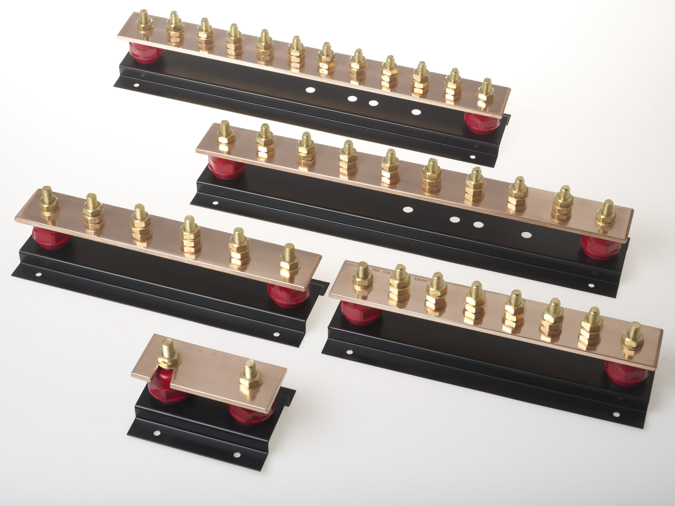
An earth bar is a conductive metal bar that provides a common connection point for electrical earthing and protective bonding conductors. Also known as an earthing bar, copper earth bar or earth marshalling bar, it helps connect electrical equipment to the wider protective earthing system.
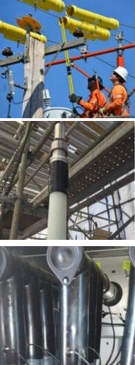
Electrical engineers use these components in substations, switchrooms, feeder pillars, industrial facilities and electrical distribution systems. They provide organised, accessible connections for protective conductors, bonding cables, copper tapes and other specified earthing connections.
Most designs use high-conductivity copper, with multiple connection points for cable lugs and conductors. Standard configurations are available alongside single-link and twin-link versions, which incorporate removable connections for authorised electrical testing.
Correct selection involves more than choosing the number of connection points. Engineers must also consider copper bar dimensions, conductor sizes, fault-current withstand, mounting arrangements and applicable electrical standards.
Thorne & Derrick supply AN Wallis copper earth bars for electrical utilities, contractors, substations and industrial infrastructure, including standard, single-link and twin-link configurations.
This guide explains how these connections work, compares the main types and examines sizes, disconnecting links, installation applications, UK requirements and product selection.
Quick Navigation – Copper Earthing Bars
- Quick Answer: What Is an Earth Bar?
- How Does an Earthing Bar Work?
- Why Is Copper Used?
- Standard, Single-Link & Twin-Link Types
- What Is a Disconnecting Link?
- Sizes, Dimensions & Connection Ways
- Where Are These Products Used?
- Earthing vs Protective Bonding
- Earth Bars vs Rods vs Tapes
- Main Earthing Terminal Explained
- UK Earthing Standards
- Selection Checklist
- Installation Considerations
- Common Specification Mistakes
- Related Products
- Frequently Asked Questions
- Conclusion
Quick Answer: What Is an Earth Bar?
An earth bar is a conductive metal component used to connect multiple earthing and protective bonding conductors at a common point. It is usually manufactured from copper and incorporates connection positions for cable lugs, earthing conductors or copper tapes.
These components help maintain electrical continuity within an earthing system. Depending on the installation, they may also provide a suitable location for inspection, testing and maintenance.
The assembly itself does not detect an electrical fault or disconnect the power supply. Its suitability depends on the complete earthing arrangement and electrical design.
How Does an Earthing Bar Work?
A copper earthing bar provides a common electrical connection between several conductors. Individual cables or tapes are terminated at designated positions using suitable fittings.
The connections allow the conductors to form part of the same earthing network, provided the components and installation are correctly designed and assembled.
What Connects to the Bar?
The electrical design determines which conductors require connections. Common examples include:
- Protective conductors connecting exposed-conductive-parts of electrical equipment.
- Main protective bonding conductors connected to relevant extraneous-conductive-parts.
- Transformer earthing conductors in suitable substation arrangements.
- Switchgear protective conductors and equipment earthing cables.
- Earth electrode conductors where specified by the earthing design.
- Functional earthing conductors where required and appropriately coordinated.
These connections may use cable lugs, bolted terminals or suitable copper tape connections, depending on the conductor and product arrangement.
What Happens During an Electrical Fault?
During an earth fault, current may flow through the protective conductor system and connected earthing components.
The bar and its connections must be suitable for the expected electrical and mechanical conditions, including any relevant fault-current duty.
The bar does not operate as a protective device. Automatic disconnection, where required, depends on the electrical installation’s protective equipment and complete fault path.
Why Are Earthing Bars Manufactured From Copper?
Copper is commonly used because it combines high electrical conductivity with useful mechanical properties and corrosion resistance.
These characteristics make it suitable for many protective earthing and bonding applications.
Electrical Conductivity
Copper allows current to flow with relatively low electrical resistance. When correctly sized, a copper assembly can provide effective electrical continuity between connected conductors.
However, its suitability must also be assessed against the prospective fault current, duration and complete connection arrangement.
Mechanical Strength
Flat copper sections provide rigid connection surfaces for drilled holes, studs and bolted terminals.
This allows several conductors to be terminated in an organised arrangement, provided the correct fittings and installation methods are used.
Corrosion Resistance
Copper offers good corrosion resistance in many environments, although its performance depends on moisture, contaminants and nearby materials.
Tinned copper versions may be specified where additional surface protection is appropriate.
For more information about surface finishes and material selection, see our Tinned Copper Earth Bars Guide.
Types of Copper Earth Bars – Standard, Single-Link & Twin-Link
Different configurations are available depending on the number of conductor connections, testing requirements and installation arrangement.
Standard Copper Earth Bars
Standard copper bars provide multiple connection points without an integral disconnecting link.
They are used where the electrical design requires a common conductor termination arrangement without the specific test-link functionality of a linked assembly.
View our Standard Copper Earth Bars.
Single-Link Designs
A single-link earth bar incorporates one removable conductive link. This can provide a designated point for particular electrical testing procedures.
The link must only be removed under approved conditions by competent personnel, because separating an earthing connection can create serious electrical hazards.
Explore Single-Link Copper Earth Bars.
Twin-Link Designs
A twin-link earth bar includes two removable conductive connections.
These assemblies can support projects that require separate designated testing connections or other specific arrangements shown on the electrical design.
The intended function of each link must be confirmed before installation or use.
Custom and Tinned Copper Options
Project-specific assemblies may be available with alternative dimensions, mounting arrangements, surface finishes and connection layouts.
The correct design should be established using the electrical drawings, conductor schedule and applicable technical requirements.
| Configuration | Main Feature | Typical Requirement |
|---|---|---|
| Standard | Multiple connection positions without an integral link. | General earthing and bonding connections. |
| Single Link | One removable connection. | A designated point for authorised testing. |
| Twin Link | Two removable connections. | Specialist arrangements requiring two test connections. |
| Tinned Copper | Protective tin surface finish. | Specified environmental or connection conditions. |
| Custom Assembly | Project-specific dimensions and connections. | Specialist electrical infrastructure. |
What Is an Earth Bar Disconnecting Link?
An earth bar disconnecting link is a removable conductive connection incorporated into a designated part of an earthing system.
It can allow authorised personnel to separate particular conductors for testing or inspection when the approved procedure requires it.
Why Are Disconnecting Links Used?
Depending on the design, they may support:
- Earth electrode resistance testing.
- Inspection of designated electrical connections.
- Verification of particular earthing arrangements.
- Planned maintenance under controlled conditions.
Important: Disconnecting links are not normal operating switches and must not be used to isolate live electrical equipment.
Removing a protective earth connection may create dangerous touch voltages or interrupt an essential fault-current path. Competent personnel must assess the risks, maintain the necessary protective arrangements and follow approved procedures.
Copper Earth Bar Sizes, Dimensions & Connection Ways
These products are available in different sizes to accommodate the required number of conductor terminations and the electrical demands of the installation.
For example, the AN Wallis range supplied by Thorne & Derrick includes designs manufactured from 50mm × 6mm copper bar, although dimensions and construction must be confirmed for the specific product.
What Does 6-Way, 10-Way or 12-Way Mean?
The number of ways normally describes the number of designated conductor connection positions.
A 6-way copper earth bar has six specified connection positions, while a 12-way assembly provides twelve.
Depending on the range, additional ways and link configurations may be available. The AN Wallis portfolio includes products with up to 30 ways.
The usable connections, link arrangement and total bar dimensions must be checked against the manufacturer’s drawings.
How Are Dimensions Selected?
Selection depends on the required conductor terminations and the complete electrical design.
Important measurements include:
- Length: Space required for connection positions and links.
- Width: Copper bar dimensions and terminal arrangement.
- Thickness: Mechanical and electrical design requirements.
- Stud or Hole Size: Compatibility with the specified cable lugs and connections.
- Mounting Centres: Position of insulators, brackets and fixing points.
- Clearance: Room for cables, tools, inspection and maintenance.
Are More Connection Ways Always Better?
Not necessarily. Additional positions can allow for future connections, but a larger assembly also requires more mounting space.
The correct number of ways should follow the conductor schedule and allow for any specified future capacity.
Where Are Copper Earthing Bars Used?
These products provide common earthing connections across electrical infrastructure, including the following applications.
Electrical Substations
Substations contain transformers, switchgear, protection equipment and multiple associated conductors.
Common copper connection points allow designated earthing conductors to be brought together within the approved substation earthing arrangement.
Switchrooms & Distribution Equipment
Electrical switchrooms may require main earthing bars or additional marshalling connections for equipment protective conductors.
The dimensions, location and connections must suit the electrical design and expected fault conditions.
Feeder Pillars
Electrical feeder pillars may incorporate suitable earthing terminals or copper bars to connect equipment within the required protective arrangement.
Industrial Facilities
Factories and industrial sites commonly contain electrical distribution equipment that requires protective conductors and bonding connections.
Accessible connection points can help organise these conductors and support appropriate inspection procedures.
Renewable Energy Installations
Solar farms, wind projects and battery energy storage sites may use common earthing connections within substations and electrical enclosures.
Data Centres
Data centres use protective earthing and bonding systems for electrical safety, alongside any separately specified functional earthing requirements.
These requirements must be coordinated within the complete electrical system.
Earthing vs Protective Bonding – What’s the Difference?
Protective earthing and protective bonding are related but different electrical safety measures.
Protective earthing connects exposed-conductive-parts to the installation’s protective earthing system. Protective bonding connects relevant extraneous-conductive-parts to help reduce dangerous potential differences.
| Function | Purpose |
|---|---|
| Protective Earthing | Supports protection against electric shock during electrical faults. |
| Protective Bonding | Helps reduce dangerous potential differences between relevant conductive parts. |
| Common Connection Bar | Provides a connection point for conductors identified by the electrical design. |
Not every metallic component automatically requires protective bonding. The classification of the part and applicable requirements must be assessed by the electrical designer.
For additional guidance, see the IET Earthing & Bonding FAQs.
Earth Bars vs Earth Rods vs Earth Tapes
Although these components are commonly used together, each performs a different function.
| Component | Main Function | Typical Application |
|---|---|---|
| Earth Bar | Provides common conductor connections. | Switchrooms and electrical distribution. |
| Earth Rod | Provides contact between an earthing arrangement and the ground. | Earth electrode systems. |
| Earth Tape | Acts as a conductor or, where designed, an electrode. | Earthing networks and equipment connections. |
| Earth Clamp | Connects compatible conductors or electrodes. | Approved earthing connections. |
How Do These Components Work Together?
For example, a substation may use buried copper earth tapes and electrodes as part of its grounding network.
These are connected to suitable earthing conductors, which may terminate at a common copper bar inside the switchroom.
However, a connection bar does not replace an earth electrode where the electrical design requires a connection with the ground.
Read our What Is an Earth Rod? guide for details about electrode types, installation depth and ground resistance.
Earth Bar vs Main Earthing Terminal (MET)
The Main Earthing Terminal (MET) is the principal connection point for designated protective earthing and bonding conductors within an electrical installation.
In some installations, a suitable copper bar performs the function of the MET.
However, not every earthing or marshalling bar is the main earthing terminal. Its function depends on the electrical design and the conductors connected to it.
What Is the Difference?
- Main Earthing Terminal: The designated principal earthing connection point.
- Copper Connection Bar: The physical component used to connect several conductors.
- Earth Marshalling Bar: A location used to organise and terminate designated earthing conductors.
Any required means of disconnecting an earthing conductor for testing must be incorporated in accordance with the applicable electrical requirements.
UK Earth Bar Standards & Technical Requirements
The applicable standards depend on the installation, product design and project specification.
BS 7671 – Requirements for Electrical Installations
BS 7671 addresses protective earthing, bonding, conductor sizing and other relevant requirements for installations within its scope.
BS 7430 – Protective Earthing
BS 7430 provides a code of practice covering protective earthing arrangements and associated design considerations.
BS EN 13601 – Copper for Electrical Purposes
BS EN 13601 specifies requirements for certain copper and copper alloy products used for electrical purposes.
Material compliance alone does not confirm the suitability of a complete assembly for its intended installation.
Fault-Current & Mechanical Requirements
When specifying a connection assembly, engineers should consider:
- Prospective earth fault current and fault duration.
- Required thermal and mechanical withstand.
- Conductor cross-sectional areas and termination sizes.
- Copper section dimensions and connection spacing.
- Mounting supports, insulation and fixing arrangements.
- Environmental conditions and corrosion resistance.
- Accessibility for inspection and authorised testing.
The complete electrical design and relevant manufacturer documentation determine the appropriate product specification.
How to Select the Correct Copper Earthing Bar
Selection involves more than choosing the required number of connection positions. The complete assembly must suit the electrical system, conductors, mounting location and expected fault conditions.
What Information Should Be Supplied for a Quotation?
Providing the conductor schedule, required number of ways, copper dimensions, mounting details and any disconnecting link requirements can help identify a suitable assembly.
Where available, include the earthing schematic, specified fault-current duty and the required material finish.
Installation & Connection Considerations
Correct installation is essential for maintaining electrical continuity and ensuring that the earthing system performs as intended.
Mounting & Accessibility
The assembly should be secured to suitable supports in the position required by the electrical design.
Connections must remain appropriately accessible for inspection, maintenance and authorised testing.
Cable Lugs & Terminations
Each conductor must be terminated using suitable fittings compatible with the conductor material, size and intended electrical duty.
Bolted connections must be assembled using the manufacturer’s requirements, including any specified tightening torque.
Identification & Labelling
Clear conductor identification helps maintenance personnel understand the intended connection arrangement and reduces the risk of incorrect disconnection.
Testing & Verification
Competent personnel must inspect and verify the completed installation using suitable procedures and test equipment.
Protective earth connections must not be disconnected during normal operation or maintenance without appropriate safety arrangements.
Common Specification & Installation Mistakes
Incorrect selection or assembly can affect the electrical performance, safety and long-term reliability of an earthing system.
- Insufficient Connection Ways: Failing to provide enough conductor termination positions.
- Incorrect Cable Lugs: Using fittings unsuitable for the conductor or terminal arrangement.
- Inadequate Fault Withstand: Ignoring prospective fault current and duration.
- Unsuitable Bar Dimensions: Selecting an assembly without adequate electrical or mechanical capacity.
- Poor Conductor Identification: Making maintenance and inspection more difficult.
- Unsafe Link Removal: Disconnecting protective connections without suitable precautions.
- Corrosion Risks: Overlooking moisture, contaminants or incompatible material combinations.
- Insufficient Access: Positioning the assembly where testing or inspection becomes difficult.
- Incorrect Bonding Arrangements: Connecting conductors without following the approved design.
- Unverified Connections: Failing to inspect or test the completed installation as required.
Correct product selection, installation and verification should be undertaken in accordance with the applicable design and electrical requirements.
Related Electrical Earthing Products
Copper earthing bars are installed alongside a range of other electrical accessories, depending on the installation.
These can include earth electrodes, copper conductors, clamps, cable lugs and approved connection systems.
For additional products, browse the wider Earthing & Copper Products range from Thorne & Derrick.
Copper Earth Bars – Frequently Asked Questions
These answers address common questions about purpose, materials, connection arrangements and installation.
Q1. What is an earth bar?
It is a conductive metal component used to connect multiple earthing and protective bonding conductors at a common point. Most designs use high-conductivity copper.
Q2. What is its main purpose?
The main purpose is to provide common electrical connections between designated conductors and help maintain continuity within the wider earthing arrangement.
Q3. Why is copper commonly used?
Copper provides high electrical conductivity, useful mechanical properties and good corrosion resistance in many installation environments.
Q4. What does a 10-way copper earth bar mean?
A 10-way design normally provides ten designated conductor connection positions. The actual configuration and any disconnecting links must be checked against the specific product drawing.
Q5. What is the difference between standard and single-link designs?
A standard arrangement has no integral disconnecting link. A single-link version includes one removable conductive connection intended for specified testing or maintenance procedures.
Q6. What is a twin-link earth bar?
A twin-link assembly incorporates two removable conductive connections, which may be specified where the electrical design requires two designated testing points.
Q7. Can a disconnecting link be removed while equipment is operating?
Protective earthing connections must not be disconnected as a normal operating action. Any approved testing procedure involving a link requires competent personnel and appropriate safety precautions.
Q8. What is the difference between an earth bar and an earth rod?
The bar connects designated earthing conductors, while a rod provides an electrical interface between an earthing system and the surrounding ground.
Q9. Is an earth bar the same as a main earthing terminal?
Not necessarily. A suitable copper bar may serve as the main earthing terminal in some installations, but other bars may be used for additional conductor marshalling or connection arrangements.
Q10. Can these products be used in high voltage substations?
Yes. Suitable assemblies are used in MV and HV substation earthing networks, subject to the complete electrical design and required fault-current withstand.
Q11. How do you select the correct dimensions?
Selection depends on conductor sizes, number of ways, fault-current requirements, mechanical support, mounting space and the manufacturer’s specifications.
Q12. When should a tinned copper finish be specified?
A tinned finish may be appropriate where additional surface protection is required. Selection should consider the environment, connected materials and project requirements.
Q13. Can custom copper earthing bars be supplied?
Custom configurations may be available with project-specific dimensions, connection positions, mounting arrangements and finishes, subject to manufacturer confirmation.
Conclusion: Selecting the Correct Earthing Connections
Earth bars provide common connection points for protective earthing and bonding conductors across electrical distribution systems, substations, switchrooms and industrial installations.
High-conductivity copper is commonly used because of its electrical and mechanical properties. Different configurations include standard, single-link, twin-link and project-specific designs.
The correct assembly should be selected according to conductor requirements, connection ways, copper dimensions, fault-current withstand, mounting details and any required testing arrangements.
Thorne & Derrick supply AN Wallis copper earthing equipment for utility, industrial and electrical infrastructure projects, with technical product information and quotation support.