What Is an Earth Rod? Types, Installation & Earthing Explained
Published 06 Nov 2026
Earth rods are metal electrodes installed in the ground to form part of an electrical earthing system. They create a connection between an electrical installation and the surrounding soil, helping the complete system perform its intended protective or operational function.
Also known as earthing rods, earth electrodes or ground rods, these components are used in electrical distribution networks, substations, industrial installations and lightning protection systems. However, their exact role depends on the earthing arrangement.
Several materials are available, including copperbond steel, solid copper, stainless steel and galvanised steel. Each provides different mechanical and corrosion-resistant properties. Therefore, the correct choice depends on the ground conditions and electrical design.
Furthermore, soil resistivity, installation depth and moisture levels can all influence electrode performance. As a result, selecting the correct material is only one part of designing an effective system.
Thorne & Derrick supply electrical earthing electrodes and accessories for utilities, contractors and industrial infrastructure projects.
This guide explains how these electrodes work, compares the main materials and examines installation, testing and UK earthing requirements.
Quick Navigation
- What Is an Earth Rod?
- How Do Earthing Electrodes Work?
- Why Are Ground Electrodes Used?
- Types of Earthing Electrodes
- Copperbond vs Solid Copper vs Stainless Steel
- Electrode Sizes and Lengths
- How Are Earthing Electrodes Installed?
- What Affects Electrode Resistance?
- How to Reduce Resistance
- Earth Electrode Testing
- UK Earthing Standards
- Typical Applications
- Electrode Selection Checklist
- Common Installation Mistakes
- Earthing Products from Thorne & Derrick
- Frequently Asked Questions
- Conclusion
What Is an Earth Rod?
An earth rod is a conductive metal electrode driven or installed into the ground. Its purpose is to provide an electrical connection between an earthing arrangement and the general mass of earth.
These electrodes form part of many electrical installations. For example, they may support fault protection, lightning protection or a wider substation earthing network.
However, installing an electrode alone does not guarantee electrical safety. Instead, it must form part of a correctly designed and tested earthing system.
What Does an Earthing Electrode Do?
The electrode provides electrical contact with the surrounding ground. Depending on the installation, this connection may support protective measures or other system requirements.
Furthermore, its performance depends on the resistance between the electrode and the soil. Therefore, ground conditions must be considered during the design process.
Quick Summary
How Do Earthing Electrodes Work?
Earthing electrodes provide a conductive connection between an electrical system and the soil. When current enters the ground, its behaviour depends on the electrical arrangement and the properties of the surrounding soil.
Unlike copper conductors, soil has relatively high and variable electrical resistivity. Consequently, the resistance of the electrode system depends on more than the metal used.
Electrical Fault Protection
In some systems, an electrode forms part of the earth fault path. However, fault current depends on the entire circuit impedance and supply arrangement.
For example, a TT earthing system commonly relies on an RCD because the earth fault loop impedance may be too high for an ordinary circuit breaker to operate within the required time.
Therefore, protective devices must be selected and verified alongside the electrode arrangement.
Earth Potential Rise
During an electrical fault, the potential of the earthing network and nearby ground may rise relative to remote earth.
As a result, voltage differences can develop across the ground surface or between accessible conductive parts.
In substations, designers must consider earth potential rise, step voltage and touch voltage. These factors are important when assessing electrical safety.
Why Are Ground Electrodes Used?
Ground electrodes are installed where an electrical design requires a connection to earth.
However, different systems have different objectives. For example, a small LV TT installation has different requirements from a high voltage substation.
LV Electrical Fault Protection
In a suitable TT arrangement, the electrode provides the installation’s connection to earth.
Nevertheless, an appropriately selected protective device is also necessary. Therefore, the electrode must be considered as part of the complete fault protection system.
Substation Earthing
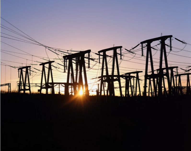
Substations often use several interconnected electrodes alongside buried tapes and conductors.
Furthermore, the design must accommodate expected fault currents and control dangerous potential differences.
Consequently, substation earthing requires specialist electrical design rather than a simple electrode installation.
Lightning Protection
Lightning protection systems may use ground electrodes as part of their earth termination network.
However, lightning current introduces different electrical and design considerations. Therefore, the complete arrangement must follow the applicable lightning protection requirements.
What Are the Different Types of Earthing Electrodes?
Several electrode materials are available. Each offers different mechanical properties, corrosion resistance and installation characteristics.
As a result, the most suitable option depends on the application and ground conditions.
Copperbond Steel Electrodes
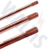
Copperbond earth rods have a steel core covered by a bonded copper layer.
This construction combines the mechanical strength of steel with the corrosion resistance of copper. Consequently, copperbond products are widely used for suitable driven installations.
In addition, threaded designs allow compatible sections to be joined for greater installation depth.
Browse Threaded Copperbond Electrode Products.
Solid Copper Electrodes
Solid copper electrodes are manufactured from copper throughout their construction.
They offer good conductivity and corrosion resistance. However, copper is softer than steel, so the installation method may differ.
For example, some designs use a drilled borehole and suitable backfill rather than direct driving.
View Solid Copper Earthing Products.
Stainless Steel Electrodes
Stainless steel provides corrosion resistance in selected demanding environments.
For example, it may be considered where ground chemistry or the presence of nearby buried metals requires particular material compatibility.
However, the correct grade must suit the installation conditions.
Explore Stainless Steel Earthing Electrodes.
Galvanised Steel Electrodes
Galvanised steel products feature a protective zinc coating.
Although they may provide an economical solution, their corrosion performance depends on the surrounding soil.
Therefore, material selection must consider the expected service life and environmental conditions.
Copperbond vs Solid Copper vs Stainless Steel
Different electrode materials offer different advantages. However, no single material is suitable for every installation.
For example, a steel-cored product may provide mechanical advantages during driving. Meanwhile, solid copper may be selected for its conductivity and corrosion characteristics.
Electrode Material Comparison
| Material | Characteristics | Selection Consideration |
|---|---|---|
| Copperbond Steel | Steel core with bonded copper coating. | Mechanical strength for suitable driven installations. |
| Solid Copper | High conductivity and good corrosion resistance. | Installation method and mechanical properties. |
| Stainless Steel | Corrosion-resistant material. | Ground chemistry and material compatibility. |
| Galvanised Steel | Zinc-coated steel construction. | Soil conditions and coating durability. |
Importantly, material alone does not determine electrode resistance. Soil resistivity, dimensions and installation depth can have a greater influence on performance.
Example – Threaded Copperbond Electrode
The following product image shows a threaded copperbond electrode arrangement from Furse.
Threaded connections allow compatible sections to form a longer electrode. However, installers must use the correct couplers and driving accessories.

View Furse RB310 Copperbond Electrode
Earth Electrode Sizes, Diameters and Lengths
Electrodes are available in different lengths and diameters to suit the earthing design.
For example, common copperbond ranges include nominal diameters of 1/2 inch, 5/8 inch and 3/4 inch. Actual shank dimensions depend on the product specification.
Meanwhile, catalogue lengths can include 1,200mm, 1,500mm, 1,800mm, 2,400mm and 3,000mm.
Does Electrode Length Matter?
Increasing the buried length generally helps reduce resistance, although the improvement depends on the soil.
For example, deeper installation may reach ground with more favourable moisture or resistivity characteristics.
However, additional depth does not guarantee a particular resistance value.
Does Electrode Diameter Matter?
Diameter influences mechanical strength and electrical performance.
Nevertheless, increasing electrode length generally has a greater effect on resistance than a comparable increase in diameter.
Therefore, the dimensions must be selected using the complete earthing design.
Can Multiple Sections Be Connected?
Yes. Some threaded electrodes are designed for extension using compatible couplers.
As a result, installers can create a longer electrode where ground conditions and the approved installation method permit.
How Are Earthing Electrodes Installed?
Installation normally involves placing the selected electrode into the ground and connecting it to the earthing system.
However, the correct method depends on the material, soil conditions and approved design.
Step 1 – Assess the Installation Location
First, review the proposed location and identify underground services.
Before driving or excavating, installers must follow suitable safe working procedures. In particular, the Health and Safety Executive’s guidance on avoiding underground services explains the importance of planning, locating buried services and safe excavation.
Step 2 – Confirm the Electrode Specification
Next, verify the material, diameter and required installed depth.
In addition, identify whether the design requires couplers, a driving head or specialist backfill.
Step 3 – Install the Electrode
Use the approved driving or borehole method to install the product.
However, excessive force or unsuitable tools may damage the electrode or its protective coating.
Therefore, the installation equipment must match the manufacturer’s instructions.
Step 4 – Connect the Earthing Conductor
Once installed, connect the electrode using the specified clamp or approved connection system.
Furthermore, the connection must be suitable for the expected environmental conditions and electrical requirements.
Step 5 – Inspect and Test
Finally, inspect the completed installation and undertake the required electrical tests.
The results must satisfy the applicable earthing design criteria. Consequently, installation depth alone cannot confirm compliance.
What Affects Earth Electrode Resistance?
Earth electrode resistance depends on the electrode arrangement and its interaction with the surrounding ground.
Although the metal is important, the soil often has a greater influence on the measured resistance.
Soil Resistivity
Soil resistivity describes the electrical resistance characteristics of the ground.
For example, wet ground may have lower resistivity than dry or rocky soil. However, actual conditions vary by location.
Moisture and Temperature
Ground moisture can affect electrical conductivity.
In addition, soil resistivity may increase during dry weather or freezing conditions.
Therefore, electrode performance should remain suitable throughout expected seasonal changes.
Electrode Depth
Deeper installation can increase contact with surrounding soil and may reach ground with different resistivity.
However, the improvement depends on the soil profile.
Multiple Electrodes
Several electrodes may be connected to form a larger earthing network.
Nevertheless, closely spaced electrodes can interact electrically through the surrounding ground.
As a result, resistance does not necessarily decrease in direct proportion to the number installed.
How Can Earth Electrode Resistance Be Reduced?
If an earthing arrangement does not meet its design requirements, improvements may be necessary.
However, the correct approach depends on the soil and available installation space.
Increase Installation Depth
Deeper installation may improve contact with lower-resistivity ground.
For example, an extended electrode may reach a more consistently moist soil layer.
Install Additional Electrodes
Adding electrodes can improve the overall arrangement.
However, suitable spacing is essential. Therefore, the layout should be determined by the design rather than simply placing rods close together.
Use Suitable Backfill Materials
Approved conductive or moisture-retaining backfill materials may be used in selected applications.
For example, bentonite can be specified for suitable earthing installations.
Nevertheless, compatibility, long-term performance and environmental suitability must be assessed.
Consider Alternative Electrode Arrangements
Where vertical electrodes are unsuitable, the design may use buried tapes, conductors or other approved arrangements.
For example, a substation may use an interconnected earthing grid rather than relying on a single electrode.
How Are Earthing Electrodes Tested?
Testing helps establish whether the installed earthing system meets the required performance criteria.
However, the suitable test method depends on the electrical installation and electrode arrangement.
Earth Resistance Testing
Specialist test equipment can measure the resistance of an electrode arrangement.
For example, the fall-of-potential method uses auxiliary test electrodes under controlled conditions.
Nevertheless, interconnected conductive systems and nearby buried infrastructure can influence results.
What Is an Acceptable Resistance Reading?
There is no universal resistance value for every installation.
For example, TT systems, substations and lightning protection systems have different design requirements.
In TT installations, appropriate protection must satisfy the relevant BS 7671 requirements, including the relationship between earth resistance and residual current device operation.
Furthermore, a resistance exceeding 200 ohms is identified in relevant IET guidance as potentially unstable under changing ground conditions. However, this is not a universal pass-or-fail threshold for all earthing systems.
For a detailed explanation, see the Institution of Engineering and Technology’s TT earthing considerations.
Why Is Periodic Testing Important?
Soil conditions can change over time, while connections may deteriorate.
Therefore, periodic inspection and testing help verify the continued suitability of the earthing arrangement.
UK Earthing Standards and Requirements
Several standards provide guidance on electrical earthing systems.
However, the applicable requirements depend on the installation type, voltage and project specification.
BS 7430 – Protective Earthing
BS 7430 provides a code of practice for protective earthing of electrical installations.
For example, it covers electrode arrangements and design considerations.
BS 7671 – Electrical Installations
BS 7671 provides requirements for electrical installations within its scope.
In particular, it addresses earthing, protective conductors and fault protection.
BS EN IEC 62561 – Lightning Protection Components
The BS EN IEC 62561 series addresses components used in lightning protection systems.
Relevant requirements include testing and performance characteristics for suitable earthing components.
Utility and Network Specifications
Electricity network operators may impose additional earthing requirements.
Therefore, substation and network projects must follow the applicable asset-owner design specifications.
Where Are Earthing Electrodes Used?
Ground electrodes are used across electrical infrastructure and industrial installations.
However, their role varies according to the electrical system.
Low Voltage Installations
In suitable TT systems, the electrode provides a local connection to earth.
As a result, its performance forms part of the overall fault protection arrangement.
MV and HV Substations
Substations may incorporate multiple electrodes, buried tapes and interconnected conductors.
Furthermore, the design must address fault current and earth potential rise.
Renewable Energy Infrastructure
Solar farms, wind installations and battery energy storage sites may use electrodes within their earthing systems.
However, the requirements depend on the project design and equipment.
Industrial Facilities
Industrial sites may require ground electrodes for particular electrical installations or infrastructure.
For example, the earthing arrangement may support an industrial distribution system.
Lightning Protection Installations
Lightning protection systems may incorporate vertical or horizontal electrodes within their earth termination network.
Therefore, selection must follow the relevant lightning protection design requirements.
How to Choose the Correct Earthing Electrode
Correct selection requires information about the electrical application, ground conditions and specified electrode performance.
For example, a product suitable for a small TT system may not meet the requirements of a high fault-current substation.
Step 1 – Confirm the Application
First, identify the type of installation and its earthing requirements.
Step 2 – Assess the Ground
Next, review soil resistivity, moisture, corrosion conditions and available installation depth.
Step 3 – Select Material and Dimensions
Then, choose the required electrode material, diameter and length.
In addition, confirm whether the installation requires threaded extensions or another specialist arrangement.
Step 4 – Check Accessories
Finally, identify compatible clamps, couplers, driving heads and conductors.
Earthing Electrode Selection Checklist
Common Earthing Electrode Installation Mistakes
Incorrect electrode selection or installation can affect electrical performance and service life.
However, appropriate planning and testing help reduce these risks.
Design and Material Selection Mistakes
- Ignoring soil resistivity: Ground conditions influence the overall resistance.
- Selecting by material alone: Dimensions and electrode arrangement also matter.
- Using incompatible metals: Dissimilar metals may increase corrosion risks.
- Assuming one resistance target applies everywhere: Requirements vary by electrical system.
- Installing electrodes too close together: Electrical interaction may reduce their combined effectiveness.
Installation and Testing Mistakes
- Failing to identify buried services: Driving operations can damage underground infrastructure.
- Using unsuitable couplers: Incorrect fittings may compromise connections.
- Damaging the electrode: Poor driving methods can affect the coating or mechanical construction.
- Ignoring connection quality: Loose or unsuitable connections may affect the earthing arrangement.
- Failing to test: Installation alone does not confirm electrical performance.
- Ignoring seasonal changes: Soil resistance may vary with moisture and temperature.
Therefore, installation should be carried out by competent personnel using the approved earthing design and safe working procedures.
Earthing Products from Thorne & Derrick
Thorne & Derrick supply earthing electrodes and associated electrical accessories for LV, MV and HV applications.
Our range includes copperbond, solid copper and stainless steel products. In addition, we supply suitable components for connection, extension and installation.
Explore Our Product Ranges
- Browse Earthing Electrode Products – the main product collection covering different materials and sizes.
- Threaded Copperbond Electrodes – suitable steel-cored copperbond products.
- Solid Copper Electrodes – copper products for specified applications.
- Stainless Steel Electrode Range – products for suitable corrosion environments.
- Electrical Earthing and Copper Conductors – related tapes, conductors, bars and accessories.
Earth Rods – Frequently Asked Questions
These answers cover common questions about electrical earthing, electrode materials, installation and testing.
General Earthing Questions
Q1. What is an earth rod?
It is a conductive metal electrode installed in the ground to form part of an electrical earthing system. As a result, it provides a connection between the installation and surrounding soil.
Q2. What is an earthing electrode used for?
These components form part of suitable earthing systems, including TT installations, substations and lightning protection networks. However, their exact function depends on the electrical design.
Q3. What materials are available?
Common materials include copperbond steel, solid copper, stainless steel and galvanised steel. Each offers different mechanical and corrosion characteristics.
Q4. What is the difference between copperbond and solid copper?
Copperbond products have a steel core with a bonded copper coating. By comparison, solid copper electrodes are manufactured from copper throughout.
Q5. Are ground rods and earthing rods the same?
Yes. Both terms describe conductive electrodes installed in the ground. However, ground rod is more commonly used in some countries outside the UK.
Installation and Electrical Testing FAQs
Q6. How deep should an electrode be installed?
The required depth depends on the earthing design and ground conditions. Therefore, no single depth is suitable for every installation.
Q7. Can multiple electrodes be installed?
Yes. Several electrodes can form part of one earthing system. However, their spacing and electrical interaction must be considered.
Q8. What affects earth electrode resistance?
Soil resistivity, moisture, temperature, installation depth and electrode arrangement all influence resistance. In particular, ground conditions may change seasonally.
Q9. What is a good resistance reading?
The acceptable value depends on the electrical system and its protective measures. Consequently, one resistance target cannot be applied to every installation.
Q10. How are ground electrodes tested?
Specialist testing methods include fall-of-potential measurements. However, the method must suit the electrode arrangement and be performed by competent personnel.
Q11. Do electrodes provide fault protection?
They can form part of an electrical fault protection arrangement. Nevertheless, the complete system must include appropriate protective measures and devices.
Q12. How do I choose the correct product?
First, confirm the earthing requirements. Next, assess the soil and required dimensions. Finally, select a compatible material and installation arrangement.
Conclusion – Choosing the Correct Earthing Electrode
Earth rods are important components of many electrical earthing systems. They provide a connection between the installation and the surrounding ground.
However, different applications require different electrode materials and arrangements. For example, copperbond and solid copper products offer different mechanical characteristics.
Furthermore, electrode resistance depends on soil conditions, installation depth and the overall design.
Therefore, appropriate selection, installation and testing are essential for achieving the required performance.
Thorne & Derrick supply specialist earthing equipment for electrical utilities, contractors and industrial infrastructure projects.
Contact our technical sales team with your material, diameter, length and application requirements to discuss suitable products.