HV High Voltage Cables | Standardization and Optimization of High Voltage Cables Design
Published 30 Oct 2019
 Thanks you Ahmed Metwally Electrical Transmission Specialist for allowing us to republish this article
Published Study for HV Cables Optimization through CIGRE-GCC 2019
Abstract
High Voltage Cables
The electric power transmission system of National Grid Saudi Arabia (a subsidiary of Saudi Electricity Company-SEC) includes a network of underground cables ranging from MV (13.8kV) to EHV (380kV) cable. The backbone of this power distribution network has a voltage rating of 110kV to 380kV with conductor cross-sectional area varying from 400sqmm to 2500sqmm.
The high voltage underground cable network has three different voltage ratings; 110kV, 115kV and 132kV. Prior to 2003, the electricity network was being operated and maintained by four individual utility companies having their own specifications and franchise areas;
- 132kV in the Central and Southern regions
- 115kV in the Eastern region
- 110kV in the Western region
National Grid initiated a study to standardize and optimize the designs for high voltage cables suitable for all high voltage ratings. The study started unifying the cables sizes and designs, verifying performance of existing network and analysing demand forecast.
Suitable designs and sizes were worked out and appropriate ways were looked into to optimize the design by implementing the relevant international standards and taking into consideration feedback from the maintenance and projects about existing cables.
Introduction to HV Cables
Utilities around the world are going for optimization of utilized equipment (reduce capital and operational cost). Therefore, Standards & Specifications Department of National Grid Saudi Arabia formed a team of experts to study the possibility of standardizing/unifying cable design to three sizes; 1200sqmm, 2000sqmm and 2500sqmm.
In addition, it will achieve financial savings as a result of this design optimizing.
Process flow for this study is shown below:

Study Process Flow
National Grid specifications have variety of high voltage cable conductor sizes which were based on IEC 60228 and the different operating areas requirements. However, based on ampacity required for each substation, National Grid is selecting 1200sqmm conductor size more often to cover load demands. And the other sizes 2000sqmm and 2500sqmm are the second most popular choices after 1200sqmm which can be applied for all substation requirements as shown in [Figure 1].

Reduction in Cable Layers
1. Reduction of Cable Insulation
The international standard IEC 60840 “Power cables with extruded insulation and their accessories for rated voltages above 30kV (Um = 36kV) up to 150kV (Um = 170kV) –Test methods and Requirements” does not specify the required nominal thickness of insulation for high voltage cables. But this is not the case with IEC 60502 which specify required nominal thickness of insulation for medium and low voltage cables.
However, the limitations of the insulation thickness for high voltage cables depends on nominal conductor electric stress which shall not exceed 8,0 kV/mm and the limitations of the insulation screen thickness depends on nominal insulation electric stress which shall not exceed 4,0kV/mm.
The required insulation thickness as pre National Grid specifications was 20.32 mm for 110/115kV cables and 21.6 mm for 132kV cables. These values satisfy the requirement of IEC 60840, but with high safety margins as shown in table 1 for 132kV cables.
Table 1
| 1200 sqmm, 132 kV cable |
2000 sqmm, 132 kV cable |
2500 sqmm, 132 kV cable |
||
| Insulation Thickness [mm] | 21.6 | |||
| The nominal Conductor electric stress [kV/mm] | 4.92 | 4.67 | 4.59 | < 8 |
| The nominal Insulation electric stress [kV/mm] | 2.62 | 2.69 | 2.77 | < 4 |
Table 2 shows parameters for 1200sqmm, 2000sqmm and 2500sqmm for 132kV cable and all the results are within the required range based on IEC 60840.
| 1200 sqmm, 132 kV cable |
2000 sqmm, 132 kV cable |
2500 sqmm, 132 kV cable |
||
| Insulation Thickness [mm] | 18.0 | |||
| The nominal Conductor electric stress [kV/mm] | 5.65 | 5.48 | 5.31 | < 8 |
| The nominal Insulation electric stress [kV/mm] | 3.26 | 3.34 | 3.43 | < 4 |
2. Reduction of Semi Conductive Layers
The same principle of the cable insulation that the IEC 60840 does not specify the required nominal thickness for cable semi-conducting layers, the team made the changes in this layer based on the manufacturers experiences when it comes to operating the triple extrusion machine and trying to maintain the eccentricity of the cable.
National Grid involved thirteen (13) cable manufacturers around the world to study and check the minimum required thicknesses for semi-conduction layer which can fulfil the requirement of eccentricity based on IEC 60840 and as a result, the conductor shield and insulation shield reduced to 1.5 mm.
3. Reduction of Metallic Screen Layer
Different metallic screens are available based on National Grid specifications. Most common choice is copper wire with tape screen [Figure 2]. Its selection mainly depends on the project requirement such as radial water tightness features, electrical and mechanical properties.
However, all metallic screen types have a fundamental function to withstand the required short circuit current.

Therefore, a critical part of designing the metallic screen is to know how much an area of metallic screen can withstand the required short circuit, IEC 60949 ” Calculation of thermally permissible short-circuit current taking into account non-adiabatic heating effect” was used to calculate the required area of metallic screen of the high voltage cable that can withstand the required short circuit.
There are two ways to do short circuit calculation; using adiabatic temperature formula and using non-adiabatic factor. In this study non-adiabatic factor chosen, by using thermal constant of the media applied over either sides of the screen. Moisture impervious layers were applied to both sides.
This helped reducing area of copper wire screen from 280sqmm “as per a adiabatic calculations” to be 261sqmm “as per non-adiabatic calculation” and still fulfilled National Grid specifications to withstand 40kA for 1 second and provided good financial savings in the cost of the high voltage cable.
These reductions in the insulation thickness and metallic screen area have also increased slightly current capacity of the optimized cable comparing with the conventional cables being used in the network.
The below Table 3 shows an example of the current rating values changes.
| 1200sqmm, 132kV cable | ||
| The load Current [A] | 914 | |
| The permissible Cable current [A] – Insulation thickness of 21.6 mm – Metallic screen area of 280 sqmm |
954* | |
| The permissible Cable current [A] – Insulation thickness of 18 mm – Metallic screen area of 261 sqmm” |
961* | + 7 |
*Installation conditions: the standard trench of a single circuit in flat formation in a backfill duct bank at 1.45 m depth with 300 mm axial phase spacing, 40 ºC soil temperature, 2.0 ºC.m/W soil thermal resistivity (dry value), 1.2 ºC.m/W thermal backfill resistivity (dry value) and cross bonded system.”
Cable Manufacturers Production Capabilities
After the completion of the design of all layers of the cable, National Grid contacted several qualified cable manufacturers (local & international) and discussed the possibility of manufacturing cables with the suggested design and its effectiveness.
The responses received were consistent with the design provided by National Grid and its specifications were updated in 2018. Subsequently, manufacturers started production of the optimized cable size 1200sqmm which was type tested successfully.
Design of the System Test Loop
After getting the success capability from the cable manufacturer and the decision to approve the optimized design, it was type tested as per IEC 60840 in addition to a short circuit test in the presence of National Grid representatives to check the quality of the new design for the electrical and non-electrical tests, the main test loop included the following components; 50 m of cable test, two outdoor porcelain terminations, one straight joint and one cross-bonding joint based on the test loop in Figure 3.

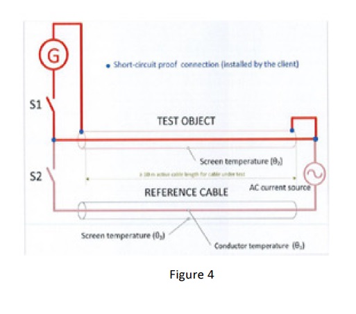
And the additional test to ensure metallic screen/sheath withstanding required short circuit was the short circuit test for which National Grid and DNV-GL “KEMA” made a procedure & the test loop The test loop is shown in Figure 4.
Financial Cost Savings
Local manufacturers were contacted for the calculation of financial savings as a result of the cable reduction and cost index [%] for HV is shown in table 4.
Benefits from this exercise in terms of financial savings in the capital budget in the next seven years were estimated to be about 25 million US dollars.
| 110kV, 115kV and 132kV Cables | ||||
| Description | 1200sqmm, Normal Design | 1200 sqmm, Optimized Design | 2000/2500 sqmm, Normal Design | 2000/2500sqmm, Optimized Design |
| Cost Index %/Km | 100 | 93 | 100 | 95 |
The Results
- Financial savings by reducing thickness of insulation & metal cover area “metallic shield” without affecting quality and efficiency of cables
- Standardization to three sizes only; 1200/2000/2500sqmm. As a result of this optimization, cable accessories will automatically be unified/standardized for specified models of cable joints and cable terminations
- Reduction in the weight of cables up to 8.6% and overall cable diameter up to 9.6%. This will facilitate the installation of cable laying thus reducing the cost of civil works
By Ahmed Metwally
Currently Electrical Transmission Specialist at Saudi Electricity Company
Job Purpose
* Approve the pre-qualification of manufacturers for electric equipment such as Cables, Cable Accessories, Link Box, SVL and Cable Cleats & Clamps.
* Authoring and updating the company specifications based on the international standards.
* Attend various type tests to verify the produced equipment is in line with requirements.
* Provide technical studies that help to use new methods in electrical transmission projects based on national and international researches.
Job Roles & Responsibilities
* Very strong experience at Extra High Voltage and High Voltage Cables and Accessories (500kV, 400kV, 380kV, 230/220kV, 132kV, 115/110kV & 69/66kV) transmission field, design, engineering, quality control and testing for substation projects.
* Attend various technical, design and progress meetings with Cables and Accessories manufacturers, SEC internal departments, and other utilities to resolve raised technical problems and to ensure smooth running of prequalification/ projects.
Achievements
* Author of the new optimized specification for high voltage cables (132/115/110kV) based on the international standard for testing and current rating calculation and induced voltage.
* Present a presentation at JICABLE2019 for the paper “Standardization and Optimization of High Voltage Cables Design.”
* Provide a technical poster at Cigre 2019 for the paper “Standardization and Optimization of High Voltage Cables Design.”
* Member of EPRI Institute – USA for EHV/HV underground cables and accessories design and installation.
Thorne & Derrick
Thorne & Derrick are national distributors of LV, MV & HV Cable Installation, Jointing, Substation & Electrical Equipment – servicing businesses involved in cabling, jointing, substation, earthing, overhead line and electrical construction at LV, 11kV, 33kV, 66kV and EHV. Supplying a complete range of power cable accessories to support the installation and maintenance of low/medium and high voltage voltage power systems:
- Slip-on Cable Terminations
- Cold-shrink Cable Terminations
- Heat-shrink Cable Terminations
- Cable Joints – Heat & Cold-shrink
- Separable Connectors (Euromold)
- Surge Arresters & Switchgear/Transformer Bushings
Key Product Categories: Duct Seals | Cable Cleats | Cable Glands | Electrical Safety | Arc Flash Protection | Cable Jointing Tools | Cable Pulling | Earthing | Feeder Pillars | Cable Joints LV | Joints & Terminations MV

Further Reading
-
 IEC 60228 International Standard
Size: 172.28 KB
IEC 60228 International Standard
Size: 172.28 KB