Water Mitigation in Data Centers by Roxtec (Cable Transit Manufacturer)
Published 18 Dec 2024
")
-
By Jason Hood, Global Segment Manager – Infrastructure Roxtec International AB
Abstract
With recent reports indicating an increased threat of extreme weather related events and rising sea levels due to climate change, critical infrastructure is expected to become more threatened by water ingress and flooding. For communication infrastructure, including data centers, it is critical to maintain operational reliability and reduce the risk of downtime.
Specifically, data centers must remain operational as downtime caused by any failure is expensive and uptime is critical. Flooding and water ingress remain a threat in extreme weather related events, but even in less extreme circumstances, water can be a nuisance and lead to longer term failures or decreased operational reliability.
Certain design considerations can be followed that will mitigate water ingress and reduce the risk of downtime.
With projected climate change effects likely, adopting effective sealing designs of openings in data centers as a best practice could effectively mitigate risk and should be considered in data center hardening strategies.
Downtime in Data Centers
Downtime is a common concern for owners and operators of data centers. Although many precautions are taken, downtime still happens. The 2014 Data Center Industry Survey, conducted by the Uptime Institute, reported that between 25% and 46% of global data center operators and IT practitioners had experienced an outage that year.1
The same survey found that 3 – 7% had experienced an outage 5 times or more (Figure 1).

Figure 1 Number of Business-Impacting Outages. Source 2014 Data Center Industry Survey, Uptime Institute
Not only does downtime occur, it is also costly. The 2016 Cost of Data Center Outages, by the Ponemon Institute, reported that the average data center outage costs $740,357.2 This survey of 63 data centers from multiple sectors (e-commerce, financial, colocation, healthcare, etc.) provides a high estimate for downtime for an average size (14090 sq. ft.) data center.
Other surveys have reported an average hourly cost of downtime exceeding $300,000.3 Data center outages happen, and when they do, the costs are substantial. With increasing reliance on technology and data, the value of data will continue to increase, which translates into higher costs for downtime in the future.
Causes of Downtime
According to the National Survey on Data Center Outages by the Ponemon Institute, UPS battery failure (65%) was reported to be the most common cause of data center outages, with 3 of the top 4 causes UPS related.4 Human error was also reported as a common cause of outages (Figure 2).

Figure 2. Causes of downtime in Data Centers, Source National Survey On Data Center Outages, Ponemon
More recently, the 2016 Cost of Data Center Outages by the Ponemon Institute also reported UPS failure as the most common cause of data center outages.2
The same report also shows that human error is a primary cause (Figure 3).

Figure 3. Causes of downtime. Source 2016 Cost of Data Center Outages, Ponemon Institute
Both surveys show that human error is a common cause of data center outages, with a value as high as 51%. Other sources claim that human error is responsible for 70% of data center outages.5 From this data, it is clear that the most common causes of downtime are human error and mechanical issues.
However, weather related events are also cited as a cause of downtime. Although there are many types of weather related events, in some areas such as the United States, 90% of natural disasters involve flooding and cause more economic damage and loss of life and property than any other natural hazard.6
While weather related events might cause fewer outages, they do occur, and the effect can be significant. The damage caused by Hurricane Sandy in 2012 was extensive, with several data centers in lower Manhattan suffering from outages and subsequently pumping basements, generator rooms, and replacing damaged switchgear to restore power.7
During this event, internet downtime doubled and took almost 4 days to recover.8 Similarly, in 2015, the UK was battered with an extreme rainfall event that caused the river Aire to exceed its banks and reach a Vodafone facility in Leeds, causing an outage for several days.9
While these are extreme examples, flooding might be a more frequent occurrence than commonly believed. For example, in a 2015 survey conducted by Zenium, 60% of respondents stated that their data centers were located in low risk areas, with 40% of facilities in the UK considered to be flood resistant.10
However, this survey also discovered that 1 in 2 data centers had experienced disruption of service due to natural disasters, including seismic activity and flooding.
Even though data center downtime is most commonly associated with mechanical issues or human error, weather related events and flooding also cause downtime, and appropriate planning should be taken to mitigate possible risks.
Site Selection
During the site selection process, factors are evaluated such as environment, climate, reliability of power, fiber connectivity, labor pool, and financial impact (taxes, land incentives). While these are all important to evaluate, it is also important to evaluate the risk of natural disasters, considering risks such as seismic activity, extreme weather and flooding.11,12,13
Data Center location is arguably the best defense against natural disasters, where avoidance of areas that are prone to natural disasters is the strategy. There are industry standards to help guide site selection to mitigate risk of flooding. For example, TIA 942 provides guidelines based on the tier rating of the data center14 (Table 1).
Table 1: Site Selection Guide for Tier Ratings. Source: TIA 942 Telecommunications Infrastructure Standard for Data Centers
| TIER 1 (A1) | TIER 2 (A2) | TIER 3 (A3) | TIER 4 (A4) | |
| Architectural | ||||
| Site Selection | ||||
| Proximity to flood hazard area as mapped on a federal Flood Hazard Boundary or Flood Insurance Rate Map | not required | not with the 50-year flood hazard area | No within 100-year flood hazard area and greater than 91m (300ft) from 50-year flood hazard area | Greater than 91m (300ft) from 100-year flood hazard area |
| Proximity to coastal or navigable inland waterways | not required | not required | Greater than 91m (300ft) | Greater than 0.8km (1/2 mile) |
Tier ratings are defined by Uptime Institute and are described based on the infrastructure required to sustain operations.15 Under this classification system, a higher tier level indicates higher site availability, thus more stringent recommendations are warranted for higher tier rated data centers. In relation to potential flooding concerns, TIA 942 follows this logic by suggesting Tier 4 data centers be located greater than 300 ft. from the 100 year flood plain and greater than 1/2 mile from coastal or inland waterways.
For environmental risks, historical data for tornadoes, hurricanes, earthquakes, and flooding can be analyzed to help identify areas prone to natural disasters. Resources such as FEMA, USGS, NOAA, European Commission and European Environmental Agency provide helpful information that can be utilized for this purpose. Historical data, as well predicted trends, can help identify areas that are at high risk of natural disasters. This type of analysis can be critical for ensuring the right location is chosen to mitigate the most risk of natural disasters.
Site selection guidelines such as these are a common sense approach to mitigate risk of natural disasters, but the risk of some level of flooding might still be possible if additional factors aren’t considered.
Specifically, site specific factors such as elevation, slope, and water table should be evaluated as water intrusion and flooding can still occur even outside of a flood zone and under moderate to heavy rainfall periods, where water table levels can become a concern. ANSI/BICSI 002 – 2014 provides good recommendations for mitigating risks of water intrusion due to water table levels.16 This standard provides several good suggestions for choosing a site with a low water table and points out potential issues with locating data centers in low lying areas where water table levels and ground water can become a concern.
Important to note is that sections 5.7.1.6.3 (electrical) and 5.7.2.4.2 (communication) both recommend service entries to be underground. While this will mitigate risks of damage to overhead lines, underground distribution is not free from threats. The effects of heavy rainfall or a high water table can be exacerbated based on specific locations of vaults, ducts and electrical equipment. ANSI/BICSI 002 recognizes this and points out that utility ducts should be above the water table and to determine if utility maintenance holes can cause water ingress based on their location.
These standards and guidelines highlight the importance of a water mitigation strategy for data centers. Placing data centers in low risk areas is a great approach to risk mitigation due to natural disasters, but even under less onerous conditions, water can be a threat that data center owners, designers and operators must contend with to mitigate risk of downtime.
The Real Threat – Water
With proper site selection and design considerations, the risk of inundation by floodwaters can be minimized. However, water issues can exist even without extreme flooding conditions. Under moderate rainfall events, flooding of the data center might not occur, yet underground fiber and power distribution ducts and vaults can fill with water. Water inside vaults, while a nuisance, (water must be pumped out for maintenance), can also lead to high humidity levels and pose a threat to power distribution systems.
For example, common failure modes of switchgear include excessive temperature, partial discharge and humidity.17 Humidity can also increase partial discharge 18 and lead to bushing failures19 and long term insulation damage.20 IEEE Standard 493-1997, IEEE Recommended Practice for Design of Reliable Industrial and Commercial Power Systems, also documents the leading causes of switchgear failure from data collected through end-user surveys.21 Appendix E from this survey reports that the leading contributing cause to switchgear bus failure was exposure to moisture (30%) for insulated bus (Table 2).
While the exposure to moisture might not directly cause a failure, it facilitates deterioration of the insulation system, leading to a failure.22 This survey also shows that the “Exposure to Dust or Other Contaminants” was the second leading contributor to insulated bus failure. This is important to note as humidity in the presence of contaminants can also increase partial discharge.23
Table 2. Contributing Causes of Switchgear Bus Failure. (Source: Paoletti, G., & Baier, M. 2002)22
| Switchgear Bus Failure Contributing Causes (%) | ||
| From IEEE Std 493-1997 Appendix E – Table XVIII | Ins. Bus |
Bare Bus |
| Thermocycling | 6.6 | – |
| Mechanical Structure Failure | 3.0 | 8.0 |
| Mechanical Damage From Foreign Source | 6.6 | – |
| Shorting by Tools or Metal Objects | – | 15.0 |
| Shorting by Snakes, Birds, Rodents etc | 3.0 | – |
| Malfunction of Protective Relays | 10.0 | 4.0 |
| Improper Setting of Protective Device | – | 4.0 |
| Above Normal Ambient Temperature | 3.0 | – |
| Exposure to Chemicals or Solvents | 3.0 | 15.0 |
| Exposure to Moisture | 30.0 | 15.0 |
| Exposure to Dust or Other Contaminants | 10.0 | 19.0 |
| Exposure to Non-Electrical Fire or Burning | 6.6 | – |
| Obstruction of Ventilation | – | 8.0 |
| Normal Deterioration from Age | 10.0 | 4.0 |
| Severe Weather Condition | 3.0 | 4.0 |
| Testing Error | – | 4.0 |
| Total | 94.8 | 100.0 |
The most common sources of humidity in substations are ambient air with high humidity, water leaks into substations, and water in cable trenches. 18 Water intrusion can cause instant issues such as short circuits.
However, the effects of water and moisture can also be longer term, where the result can be insulation damage, corrosion, cable and equipment failure. One of the most commonly documented examples of longer term insulation damage from water on medium voltage cables is water treeing,24 which is a micro-crack propagation of degraded insulation (Figure 4).
These micro-cracks grow from stress points in the presence of water and can eventually lead to cable failure. These stress points are usually caused from manufacturing, transportation, pulling cables or service of cables.

Figure 4 Examples of water trees in power cable insulation
While typical duct designs can ensure proper slope to direct water away from buildings and equipment, and vaults can be located above the water table, moisture can still be present inside vaults or ducts leading to and away from generators, switchgear, load banks and transformers.
This moisture can cause long term damage by facilitating insulation breakdown. Using cables optimized for these environments (e.g. TR-XLPE or LC) can reduce the risk, but not all cables failures are due to a breakdown in cable insulation.
Splices, cable terminations and cable joints are also a potential weak link as poor workmanship can lead to water ingress. The effects of water might not be immediate, and longer term, water in and around power distribution ducts and equipment can lead to premature cable failure.
Not only are power cables at risk, underground fiber optic cables are also threatened by moisture. While locating fiber optic cables underground removes inherent dangers of aerial placement, underground locations can be subjected to constant exposure to water inside ducts and vaults. The effects of moisture on fiber optic cables are well documented. 25,26,27,28 Some of the effects are signal attenuation due to water molecules embedding in micro-cracks, corrosion of connectors, signal loss and mechanical damage due to freezing.29
The effects of water can be minimized by using the correct type of cable. Typically, outdoor cables are designed to minimizes water penetration with the use of gel-filled tubes or waterswellable materials and are durable for harsh environments. As is the case with power cables, even with proper cable selection, the connections can be the weakest link. Using the right materials can minimize damage from moisture, but preventing water ingress and minimizing moisture where possible will provide the optimum protection of critical fiber optic infrastructure.
Climate Change
Even if proper site selection is achieved, will it be enough for the future? Climate change seems to be changing the rules and could potentially be the biggest threat to infrastructure. For example, in the UK, increased frequency of coastal, fluvial or pluvial flooding is expected to damage key ICT assets such as cables, masts, pylons, data centers, telephone exchanges, base stations or switching centers30 and increased flooding from all sources is the most significant risk to infrastructure.31
One of the most striking assessments highlighting the potential impact of climate change in the UK is a report by AEA compiled for DEFRA, the UK’s Department of Environment, Food and Rural Affairs. The report, Adapting the ICT Sector to the impacts of Climate Change, provides information related to underground and above ground infrastructure.32 The following points summarize some of the potential impacts of flooding:
- Elements of infrastructure below ground are vulnerable to flooding, rising water tables, water ingress
- Above ground – risks from precipitation, unstable ground, and humidity
- Flooding of conduits, increased risk of flooding low-lying areas, access holes and underground facilities
In the US, the report Climate Change Impacts in the United States: The Third National Climate Assessment, U.S. Global Change Research Program reports similar information.33
Some of the key findings from the report are:
- Infrastructure is being damaged by sea level rise, heavy downpours and extreme heat; damages are projected to increase with continued climate change
- Over the past century, global average sea level has risen by 8 inches
- Since 1992, sea level rise has been almost twice the rate observed over the last century
- Sea level rise combined with coastal storms has increase the risk of erosion, storm surge damage, and flooding for coastal communities
- Sea level is expected to increase 1 to 4 feet over this century
Coastal communities are at the greatest risk of storm surges and rising sea levels. Combined tide levels and rising sea levels is already contributing to chronic flooding in many US cities. Although it’s uncertain to know exactly how much sea level will rise in the future, moderate projections for sea rise predict nearly 490 communities in the U.S. will face chronic inundation by the end of the century.34 Additional scenarios show the number as 668 communities affected (Table 3).
Although most of the communities are small, larger cities will be affected such as Boston, New York, Miami, San Mateo and Newark. Of course, data centers are already located in these cities and undoubtedly, some could be at risk of flooding.
A recent paper, Lights Out: Climate Change Risk to Internet Infrastructure predicts that in 2030, with a 1ft rise in sea level, 235 data centers will be affected, as well as 771 POPs, 53 landing stations, and 42 IXPs.29
Table 3. Communities Facing Chronic Inundation As Sea Level Rises
Source: When Rising Seas Hit Home: Hard Choices Ahead for Hundreds of US Coastal Communities, Union of Concerned Scientists, July 2017
| Low Scenario | Intermediate Scenario | High Scenario | ||||||||||||
| % inundation | Present | 2060 | 2100 | 2035 | 2060 | 2080 | 2100 | 2030 | 2045 | 2060 | 2070 | 2080 | 2090 | 2100 |
| 10-25% | 44 | 63 | 112 | 64 | 103 | 133 | 195 | 75 | 109 | 152 | 165 | 208 | 226 | 240 |
| 25-50% | 31 | 53 | 61 | 49 | 71 | 76 | 102 | 55 | 78 | 89 | 89 | 110 | 125 | 155 |
| 50-75% | 12 | 42 | 58 | 37 | 50 | 74 | 59 | 30 | 44 | 71 | 69 | 71 | 81 | 76 |
| ≥75% | 4 | 25 | 59 | 17 | 48 | 82 | 133 | 18 | 34 | 68 | 104 | 134 | 170 | 197 |
| Total | 91 | 183 | 290 | 167 | 272 | 365 | 489 | 178 | 265 | 360 | 427 | 523 | 600 | 668 |
The following are key points from this paper:
- Sea level rise is projected to be 1 – 6 ft. by the year 2100
- Under the most modest projection, 4,067 miles of fiber conduit will be under water
- Internet infrastructure is designed to be weather and water resistant. They are not designed to be surrounded by or under water
- Risks include physical damage at landing stations, physical damage via tidal inundations and corrosion leading to signal loss
- Buried conduits will become submerged
- Much of the infrastructure was deployed over the past 20 years and is aging, meaning that all seals and claddings are likely to vulnerable to damage if they are under water
For new data centers, choosing to build outside of coastal areas seems like a safer option, but this option is not risk-free. Heavy rainfall events are increasing, which can also increase the risk of flooding. In the US, heavy downpours have increased in certain areas by as much as 71% (Figure 5).33
")
Figure 5 Changes in the amount of precipitation from very heavy events (1958-2012)
Source: Climate Change Impacts in the United States: The Third National Climate Assessment, U.S. Global Change Research Program. 2014. (Updated from Karl et. al 2009)35
Part of the reason for an increase in heavy downpours can be attributed to a warmer climate. For every 1 degree Celsius, there is 7% more moisture in the air.36 Based on the predicted global temperature rise of 3 – 5 degrees, heavy downpours could become even more frequent in the future, causing localized flooding and changing flood boundaries.
Even with reports such as these, in a recent survey of 867 data center operators and IT practitioners, only 14% reported that were taking climate change into considerations and “re-valuating site selection based on higher temperatures, increased flooding, or water scarcity.” 37
In the same survey, only 11% reported they are taking steps to mitigate increased flood risk. Although these numbers are low, they show that the threat of climate change and flooding is starting to be recognized and that some data center operators will implement a proactive water mitigation strategy.
Water Mitigation
Standards, such as ANSI/BICSI 002-2014 and TIA 942, do provide some guidelines for mitigating risk of water ingress. TIA 942 recommends a floor drain be placed in areas where risk of water ingress exists. It also states “the data center and all support equipment should be located above the highest expected floodwater levels. No critical electronic, mechanical or electrical equipment should be located in basement levels.”
In practical terms, this isn’t always the case. Even if equipment is at ground level, feeders often enter substations below ground and can become a pathway for water and humidity. In these areas, it is common to utilize pumps and dehumidifiers to remove water and humidity. These are all good design practices, but an often overlooked area is the utility ducts and distribution vaults as a water and humidity source.
Commonly, specifications will point to some type of sealant for ducts, but many times, there is nothing installed and ducts are left open (Figure 6).

Figure 6. Unsealed ducts quickly fill with water and debris
On-site remedies vary, but most commonly, foam or silicone is used (Figure 7). While these remedies will provide some level of protection, they are not effective long-term at stopping water pressure that builds up behind the seal.

Figure 7. Silicone and foam used to stop water ingress
In this scenario, ducts, vaults and maintenance holes fill with water and debris, where cables and equipment can be exposed to high levels of water and humidity. This is the highest risk scenario and is very common when construction specifications do not include details for sealing cable ducts and building entries.
In many cases, after a problem with water ingress has been discovered, some type of maintenance procedure is established to solve the problem.
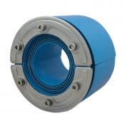
Mechanical sealing solutions, using standard or customised cable transits, that are purpose built for sealing underground ducts provide the highest level of protection. These solutions from Roxtec are typically a compressed rubber solution with tight tolerances that, when compressed, provide a water-tight seal that will contain a high level of water pressure for long term reliability (Figure 8). These solutions are designed for life of building duration or maintenance schedule.

Figure 8. Mechanical seals for fiber and power vaults. Purpose built seals that provide long term protection against water ingress
Sealing underground power and fiber ducts can be one of the most effective and least costly methods for protecting critical infrastructure from water and humidity. Without solutions that are purpose designed for stopping water, ducts can become a pathway for water ingress during flooding events.
Even in less severe weather conditions, ducts can be a source of humidity which can effect short and long-term operational reliability of fiber and power systems.
Other areas that are potential points of water ingress include cable and pipe penetrations for:
- Data Center Cooling/Rooftop penetrations (Figure 9)
- Power systems (Generator/load bank, transformer/switchgear) exterior wall (Figure 10)
- Fiber/Network Room

Figure 9. Rooftop penetration protected against water ingress

Figure 10. Large area building penetrations for power systems sealed against water ingress
These are all common points of water ingress that need to be protected. However, all penetrations through the building envelope should be evaluated as a potential leak path and appropriate solution applied to mitigate water ingress into the data center.
Conclusion
Downtime in data centers happens. Recent surveys show that downtime is still a concern for owners and that the reasons for downtime vary. Although most downtime occurs due to human error or mechanical issues, water related issues occur causing short and long term consequences. With proper design and site selection, water related issues in data
centers can be minimized. However, with climate change projections, data center fiber and power infrastructure will become more threatened by flooding and water ingress. Building away from coastal areas and outside of flood zones makes sense, but might not always be possible.
Based on a risk assessment of existing data centers, appropriate hardening measures can be taken to mitigate water ingress and protect power and fiber to ensure long-term operational reliability and uptime. For future data centers, designing and implementing purposed designed sealing solutions can offer the best long-term protection against the threat of water.
References
- Uptime Institute, & Heslin, K. (2014). Data Center Industry Survey. [Online at https://Journal.uptimeinstitute.com/ 2014-data-center-industry-survey]
- The Ponemon Institute. (2016, January). Cost of Data Center Outages. [Online at https://www.vertivco.com/globalassets /documents/reports/2016-cost-of-datacenter-outages-11-11_51190_1.pdf]
- Information Technology Intelligence Consulting, & DiDio, L. (2017). Hourly Cost of Downtime and Minimum Reliability Requirements Survey.
- The Ponemon Institute. (2010, September). National Survey on Data Center Outages. [Online at https://www.ponemon.org/local/ upload/file/Data_Center_Outages.pdf]
- Onag, G. (2016, October 17). Uptime Institute: 70% of DC Outages due to human error. [Online at https://www. cw.com.hk/it-hk/uptime-institute-70- dc-outages-due-to-human-error]
- Department of Homeland Security. [Online at https://www.dhs.gov/ natural-disasters]
- Miller, R. (2012, November). New York Data Centers Battle Back from Storm Damage. [Online at https://www. datacenterknowledge.com/archives/ 2012/11/01/ny-data-centers-battleback-from-storm-damage]
- Heidemann, J., Quan, L., & Pradkin, Y. (2013, February). A Preliminary Analysis of Network Outages During Hurricane Sandy (USC/ISI Technical Report ISI-TR685b). [Online at https://www.isi.edu/ ~johnh/PAPERS/Heidemann12d.pdf]
- Lima, J. (2016, January). Severe Floods in Leeds Hit Vodafone Data Centre. [Online at https://www. cbronline.com/news/data-centre/ severe-floods-in-leeds-hit-vodafonedata-centre-4767027/]
- Zenium Technology Partners Limited. (2015). Managing Growth, Risk and the Cloud (Executive Summary of Independent Market Research Commissioned by Zenium Data Centers).
- Uptime Institute. (2010 – 2014). Data Center Site Infrastructure Tier Standard: Operational Sustainability. [Online at https://uptimeinstitute.com/publicatio ns]
- Bowman, R. & Deneny, T. (2014, November). Data Centers: Site Selection 101 | Site Selection Online. [Online at https://siteselection.com/issues/2012/ nov/data-centers.cfm]
- Mena, M., Musilli, J., Austin, E., Lee, J.,
& Vaccaro, P. (2014). Selecting a Data Center Site: Intel’s Approach. (IT@Intel White Paper. Data Center Site Selection). [Online at https://media14. Connected com/intel/02/ 11447/IT_Best_Practices_Data_Center_ Site_Selection.pdf] - Telecommunications Infrastructure
(2012, August). Telecommunications Infrastructure Standard for Data Centers (TIA-942-A). - Uptime Institute. (2009 – 2018). Data
Center Site Infrastructure Tier Standard: Topology. [Online at https://uptime com/publications] - (2014). ANSI/BICSI 002-2014.
Data Center Design and Implementation Best Practices. - Murray, J., & Andle, J. (2016). The Eye
on Medium Voltage Switchgear. Protecting critical assets with wireless monitoring. [Online at https://www. emerson.com/documents/automation/- eye-on-medium-voltage-switchgear-en38314.pdf] - EA Technology, & Byrne, T. (2013,
January). Humidity Effects in Substations. [Online at https://www. roxtec.com/globalassets/03.-files/ whitepapers/humidity_ effects_in_substations.pdf] - van Heerden, C., & Rogerson, A. (n.d.).
Bushing Failures in Medium Voltage Switchgear. [Online at http://www. ameu.co.za/Portals/16/Conventions/Co nvention%202009/Papers/Bushing%20f ailures%20in%20medium%20voltage%2 0switchgear%20-%20Coetzee%20 van%20Heerden.pdf] - Genutis, D. (2010). Top Five Switchgear Failure Causes and How to Avoid Them. [Online at https://www.netaworld.org/ netaworld-journal/archived-articles/ 505]
- (1997). Recommended Practice for the Design of Reliable Industrial and Commercial Power Systems. IEE std 493 – 1997.
- Paoletti, G., & Baier, M. (2002). Failure Contributors of MV Electrical Equipment and Condition Assessment Program Development. IEEE Transactions on Industry Applications, 38(6), 1668 – 1676.
- Schneider Electric Industries. (2018, June). Medium Voltage Technical Guide, Basics for MV Cubicle Design. [Online at https://www.schneider-electric.com/ en/work/products/product-launch/ medium-voltage-technical-guide/]
- Mecheri, Y., Nedjar, M., Lamure, A., Aufrey, M., & Drouet, C. (2010). Influence of Moisture on the Electrical Properties of XLPE Insulation. 2010 Annual Report Conference on Electrical Insulation and Dielectric Phenomena (CEIDP). 1-4.
- (2014). The Impact of Water on Fibre Optic Cable. [Online at https://www.idacs.uk.com/images/uploads/downloads/Datwyler_WP_Waterjmpact_FO_2014.pdf]
- Grover, W. (2004, February). Fiber Cable Failure Impacts, Survivability Principles, and Measures of Survivability. InformIT. [Online at http://www.informit.com/articles/articlaspx?p=169456]
- Corning, & Jacobs, J. (2004, September).
The Impact of Hydrogen on Optical Fibers. [Online at https://www.corning. com/media/worldwide/global/docume nts/sfiber%20WP9007_Hydrogen%20Ag ing.pdf] - Cisco, & Alwayn, V. (2004, April). Fiber‑
Optic Technologies. [Online at http://www.ciscopress.com/ articles/article.asp?p=170740&seqNum =6] - Durairajan, R., Buford, C., & Buford, P.
(2018, July). Lights Out: Climate Change Risk to Internet Infrastructure, ANWR. [Online at https://ix.cs.uoregon. edu/~ram/papers/ANRW-2018.pdf] - Fu, G., Horrocks, L., & Winne, S. (2016)
Exploring impacts of climate change on UK’s ICT Infrastructure. Proceedings of the ICE Infrastructure Asset Management, 3, 1,42-52 - Dawson, R.J., Thompson, D., Johns, D.,
Gosling, S., Chapman, L., Darch, G., Watson, G., Powrie, W., Bell, S., Paulson, K., Hughes, P., & Wood, R. (2016). UK Climate Change Risk Assessment Evidence Report: Chapter 4, Infrastructure. Report prepared for the Adaption Sub-Committee of the Committee on Climate Change, London - Horrocks, L., Beckford, J., Hodgson, N.,
Downing, C., Davey, R., & O’Sullivan, A. (2010). Adapting the ICT Sector to the Impacts of Climate Change – Final Report, Defra contract number RMP5604. AEA group, published by Defra. - Melillo, J.M., Richmond, T.C., & Yohe, G.W., Eds. (2014). Climate Change Impacts in the United States: The Third National Climate Assessment. U.S. Global Change Research Program, 841 pp. doi:10.7930/J0Z31WJ2.
- Spanger-Siegfried, E., Dahl, K., Caldas, A., Udvardy, S., Cleetus, R., Worth, P., Hernandez Hammer, N. (2017). When Rising Seas Hit Home. Hard Choices Ahead or Hundreds of US Coastal Communities. Union of Concerned Scientists. [Online at https://www. ucsusa.org/global-warming/global-warming-impacts/when-rising-seas-hit-home-chronic-inundation-from-sea-level-rise#.W9D8YZNKjnY]
- Karl, T.R., Melillo, J.T., & Peterson, T.C., Eds. (2009). Global Climate Change Impacts in the United States. Cambridge University Press, 189 pp. [Available online at http://downloads. globalchange.gov/usimpacts/pdfs/ climate-impacts-report.pdf]
- Carey, J. (2011, June 29). Global Warming and the Science of Extreme Weather. [Online at https://www. scientificamerican.com/article/global- warming-and-the-science-of-extremeweather/]
- Uptime Institute. (2018). Uptime Institute Global Data Center Survey, Operators struggle with constraints, change, and complexity. [Online at https://uptimeinstitute.com/2018-datacenter-industry-survey-results]
THORNE & DERRICK
Thorne & Derrick are national distributors of LV, MV & HV Cable Installation, Jointing, Substation & Electrical Equipment – servicing businesses involved in cabling, jointing, substation, earthing, overhead line and electrical construction at LV, 11kV, 33kV, 66kV and EHV. Supplying a complete range of power cable accessories to support the installation and maintenance of low/medium and high voltage cable systems:
- Slip-on Cable Terminations
- Cold-shrink Cable Terminations
- Heat-shrink Cable Terminations
- Cable Joints – Heat & Cold-shrink
- Separable Connectors (Euromold)
- Surge Arresters & Switchgear/Transformer Bushings
Key Product Categories: Duct Seals | Cable Cleats | Cable Glands | Electrical Safety | Arc Flash Protection | Cable Jointing Tools | Cable Pulling | Earthing | Feeder Pillars | Cable Joints LV | Joints & Terminations MV