Cold Shrink Glands for MV HV Cables
Published 21 May 2025
How to Install SPS 180 & SPS 193 Cold Shrink Cable Glands
To suit 3 Core SWA Armoured XLPE Cables, 3.6kV (3.3kV) to 36kV (33kV)
Reference Numbers: SPS 180(CS) and SPS 193(CS)
In this Post, we present a step-by-step installation guide for the SPS 180(CS) and SPS 193(CS) Cold Shrink ‘Bolt-On’ Type Cable Glands. These “top-hat” glands are designed to connect and gland 3-core armoured XLPE cables from 3.6kV to 36kV, providing a reliable and easy-to-install solution for Cold Shrink termination and are distributed by Thorne & Derrick.
Note:- Fig 1 shows one possible cable gland configuration, in some situations it may be necessary to position the 3 leg heat shrink boot body below the gland plate to gain space within the cable box. If cable is non armoured, additional strain may be put on the heat shrink tube to ensure cable is supported by cable cleats to provide additional strain relief.
Step-by-Step Installation Guide
1. Cable Preparation
-
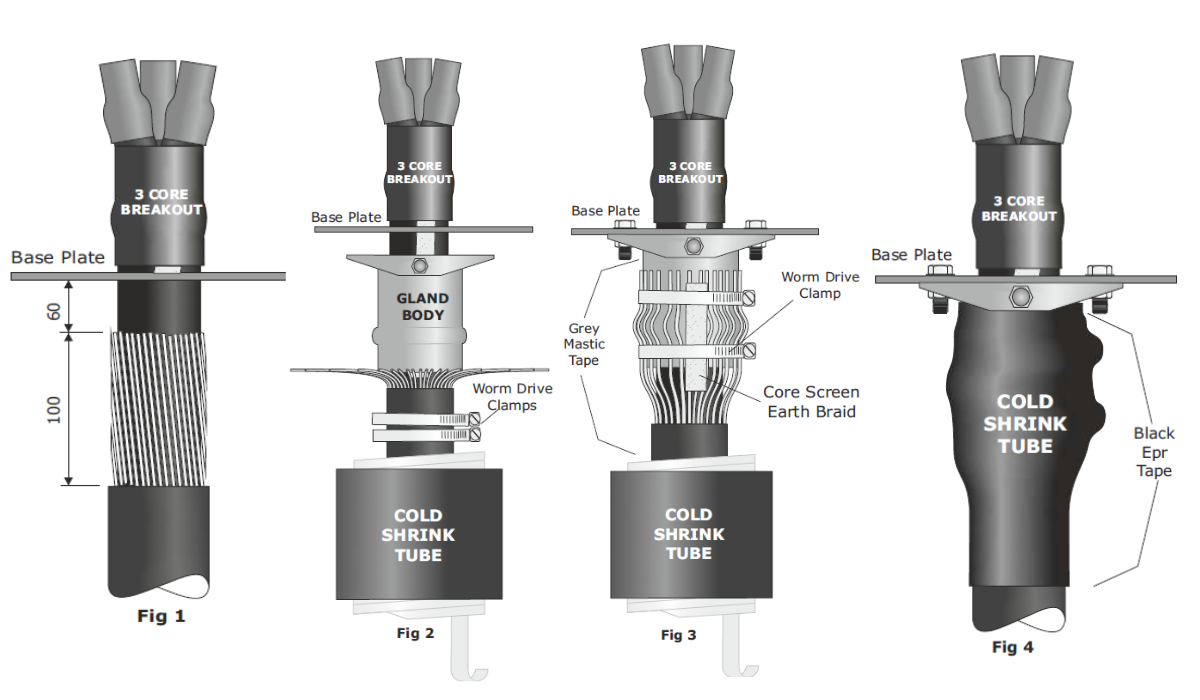
Before opening up the armour wires, ensure the cold shrink tubes and the two worm drive clamps are in position.
2. Armour Wires
-
Open up the wire armours as shown in Fig 2.

3. Cable Gland Body
-
Slide the metal cable gland body over the cable.
Note: The cable gland body itself can, in most cases, be positioned after completing the cable termination.
For Steel Tape Armoured Cable:
Prepare to the same dimensions shown in Fig 1 and follow section 7 (see below).Configuration Tip:
Fig 1 shows one possible configuration. In some cases, you may need to position the 3-leg boot body below the gland plate to gain space within the cable box.Non-Armoured Cable Warning:
Additional strain may be placed on the shrink tube. Ensure the cable is supported by cable cleats to provide strain relief.
4. Final Connections
-
Complete the final connections of the cable termination before bolting the cable gland body in place.
5. Bend Armour Back
-
Bend the armours back over the cable gland body.
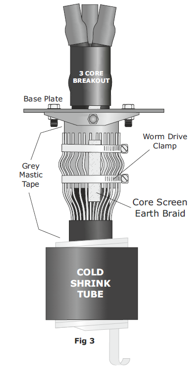
6. Clamping
-
Using the worm drive clamps, connect the cable armours and screen earth braids to the cable gland body as shown in Fig 3. Ensure the cable clamps are tight.

7. Cover Edges
-
Cover any sharp edges and the clamp buckles with PVC tape.
If Steel Tape Armoured:
Unwind the electrical tape below the bottom of the cable gland, re-wrap around the cable gland body, and secure with worm drive clamps.
8. Moisture Seal
-
To provide a moisture seal, stretch and apply a turn of grey mastic tape around:
-
The top of the metal cable gland body.
-
The outer cable jacket.
-
This ensures that the cold shrink tube will recover properly onto the tape.
9. Apply Cold Shrink
-
Position the cold shrink tube.
-
Begin pulling the plastic spiral carefully.
-
Do not pull the spiral straight.
-
Wrap it around the cable to avoid snagging.
-
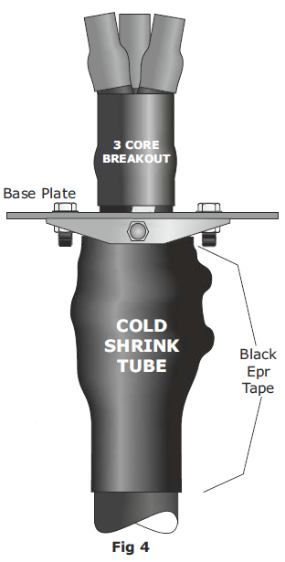
10. Secure Ends
-
Once fitted, apply the provided black EPR tape at both the top and bottom of the tube.

Figures for Reference
-
Fig 1: Base plate and initial configuration
-
Fig 2: Wire armour open-up
-
Fig 3: Clamp setup with screen earth braid
-
Fig 4: Final assembly with cold shrink and sealing tapes
Cable Glands Distributed from Stock by Thorne & Derrick | the 501/453 range of Universal Cable Glands manufactured by Hawke are suitable for the mechanical retention, glanding and termination of LV MV HV Power Cables with steel wire armour, steel wire braid or steel tape armour.

Shrink Polymer Systems heatshrink cable joints and terminations suit all types of MV-HV electrical cables (single or multi-core) with or without armour or lead sheaths – zero halogen and fire resistant cable joints are also available.


