GRP Feeder Pillars – A Short Guide To Site Installation
Published 09 Oct 2019

GRP Feeder Pillars – A Short Guide To For Site Installation
-
uploaded by Chris Dodds | Thorne & Derrick Sales Marketing Manager
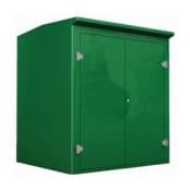
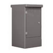
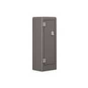
GRP Feeder Pillars
The following article has been written to provide guidance to civil engineering and groundworks contractors for the installation of GRP feeder pillars used to provide low voltage electrical power distribution.
Step 1. Concrete base must be clean and free from any earth, stones or any other debris which will prevent the feeder pillar or kiosk sitting flat on its base – it is recommend that a stepped base be cast for feeder pillasr where the inner level is 50mm above the base flange, so as to prevent water ingress into the kiosk.
Step 2. Orientation of the feeder pillar is to be agreed before the pillar is positioned on to its base. It is good practice to have the pillar sitting in the middle of the base with an equal amount of slab around the pillar. The feeder pillar can be manoeuvred using a jemmy bar from inside or outside the unit; care is to be taken so as not to damage the gel surface.
Step 3. Check for an equidistant gap between the door and door frame and that the doors operate freely. The doors can be adjusted by placing shims between the base and the feeder pillar directly in line with the door hinges; these shims should be of non corrosive metal, plastic or even GRP.
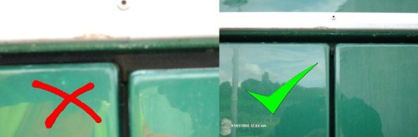
Check for an equidistant gap between the door and door frame and that the doors operate freely
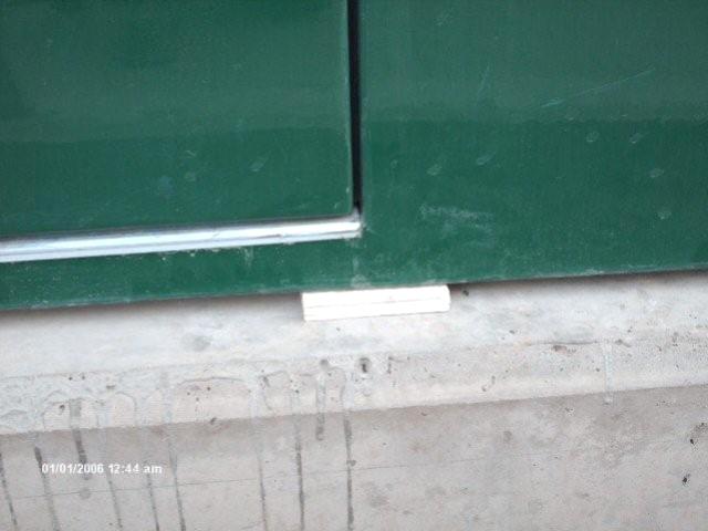
Packing shim
Step 4. Ensure that walls of the pillar are straight and are not “bowing”.
Step 5. Drill 12mm holes in the GRP base flange of the pillar at approximately one metre intervals using a battery drill (some feeder pillars may have already been pre drilled).
Step 6. Various anchor bolts can be used to pin the feeder pillars down depending on site specification – it is recommended to use an M 10 x 75mm sleeve anchor expansion bolt as standard. Size and depth of the hole should be in accordance with the fixing being used.
Step 7. Drill should be used at right angle to the concrete base; however, the holes can be drilled at an angle where a plywood board may prevent the drill from operating at 90 degrees.
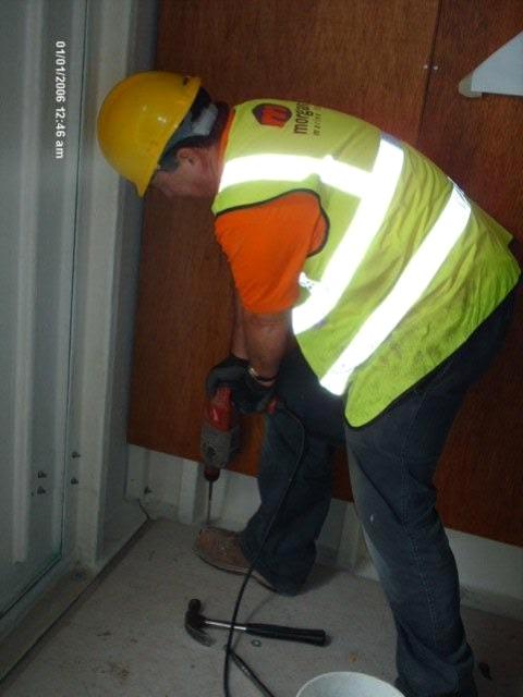
Drill should be used at right angle to the concrete base
Step 8. Re-check door levels after bolting down the pillar.
Step 9. Apply a bead of silicon to fill the gap between the feeder pillar and concrete base. This cannot be relied upon to provide a water tight seal; it is used for cosmetic purpose and will also prevent any concrete screed from running down the face of the concrete base.
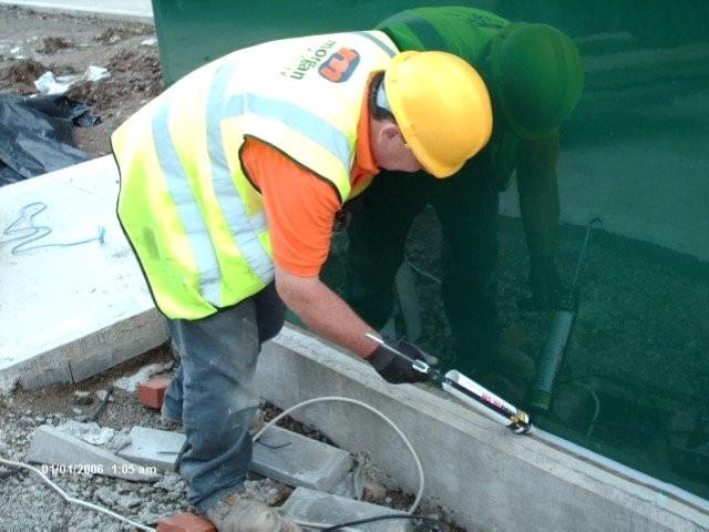
Apply a bead of silicon to fill the gap between the kiosk and concrete
Step 10. Remove the lifting eyes and seal holes with the plastic bungs provided.

Feeder Pillars – Galvanised Steel | Stainless Steel | Cast Iron | GRP
Thorne & Derrick
T&D are Specialist Distributors to UK Distribution Network Operators (DNO’s), NERS Registered Service Providers, ICP’s and HV Jointing Contractors of an extensive range of LV, MV & HV Jointing, Earthing, Substation & Electrical Eqpt – this includes 11kV/33kV/66kV joints, terminations and connectors for both DNO and private network applications.
Contact our UK Power Team for competitive quotations, fast delivery from stock and technical support or training on all LV-HV products.
Key Product Categories: Duct Seals | Cable Cleats | Cable Glands | Electrical Safety | Arc Flash Protection | Cable Jointing Tools | Cable Pulling | Earthing | Feeder Pillars | Cable Joints LV | Joints & Terminations MV HV