Four ways of ensuring proper selectivity in MV HV electrical network protection (photo credit NSS Ltd)
MV/HV Electrical Network Protection
With Kind Permission of: Edvard Csanyi (Editor-In-Chief & Electrical Engineer at EEP)
Selectivity study of a power system is usually considered as an advanced job for advanced engineers, mostly relay protection engineers.
This article will try to get close to a few important selectivity principles in a simple manner. It’s important to fully understand that protective devices form a logical system in relation to the power system structure and its earthing system.
Protective devices are the brain of a power system based on the principle of selectivity that consists of isolating the part of the network affected by the fault, and only that part, as quickly as possible, while all the other unaffected parts of the network remain energized.
There are various ways of ensuring proper selectivity in electrical network protection..
Time-graded selectivity (using time),
Time-graded selectivity with independent time overcurrent protection
Time-graded selectivity with inverse time overcurrent protection
Logic selectivity (via information exchange),
Directional protection selectivity,
Differential protection selectivity,
1. Time-graded selectivity
Time-graded selectivity consists of setting different time delays for the overcurrent protection devices distributed throughout the network. The closer the protection is to the source, the longer the time delay. See Figure 1.
Thus, in Figure 1, the fault shown is detected by all the protection devices (at A, B, C and D). The time-delayed protection at D closes its contacts more quickly than the one installed at C, which in turn reacts more quickly than the one located at B.
Figure 1 – Time-graded selectivity
Once circuit-breaker D has been tripped and the fault current has been cleared, protection devices A, B and C, through which the current no longer passes, return to standby position.
The protection devices are activated when the current rises above the pre-defined setting. The threshold settings must therefore be coherent. The difference in operating times ∆tbetween two successive protection devices is the selectivity interval.
It takes into account:
Circuit-breaker breaking time tc
Time delay tolerances δt
Upstream protection memory time tm
Safety margin
∆t must therefore satisfy the relation: ∆t ≥ tc + tm + 2δt + margin (see Figure 2)
Taking into account the present performances of switchgear and protection devices, ∆t is assigned a value of 0.3 seconds (after detailed examination it is sometimes possible to take 0.25 seconds).
For example, for the independent time-phase overcurrent protection devices of the protection relay associated with medium voltage circuit-breakers (see Figure 2):
tc = 85 ms
tm = 55 ms | maximum values
δt = 25 ms
Figure 2 – Time-delay selectivity interval of protection devices A and B
This selectivity system has two advantages:
It provides its own back-up. Indeed, the protection at Cwill be activated if the protection at Dfails (a healthy part of the installation is cut off);
It is simple.
However, when there are a large number of cascading relays, the fault clearing time is prohibitive and incompatible with the short-circuit current withstand of equipment, or with outside operating requirements, owing to the fact that the protection furthest upstream has the longest time delay. Thus, the highest fault current is cleared after the longest time delay.
Both types of overcurrent protection (independent and inverse time) can be used.
1.1 Time-graded selectivity with independent time overcurrent protection
The protection time delay is constant and independent of the current. The protection tripping curves are shown in Figure 3.
Figure 3 – Time-graded selectivity with independent time overcurrent protection
The current threshold settings must be such that:
Iset, A > Iset, B > Iset, C > Iset, D
Iset, A > Iset, B > Iset, C > Iset, D : current thresholds of protection devices A, B, C and D.
It is estimated that the accuracy of the measuring unit is 10%. Two successive protection devices must therefore comply with the following relation:
0.9 × Iset, A > 1.1 × Iset, B or
Iset, A ≥ 1.22 × Iset, B
In practice, the following values are taken:
Iset, A ≥ 1.25 × Iset, B
Iset, B ≥ 1.25 × Iset, C
Iset, C ≥ 1.25 × Iset, D
1.2 Time-graded selectivity with inverse time overcurrent protection
The greater the current, the shorter the time delay. The protection tripping curves are shown in Figure 4.
Figure 4 – Time-graded selectivity with inverse time overcurrent protection
If the current thresholds are set at a value close to In , both protection against overloads and protection against short circuits are ensured. The following values are, for example, taken:
Iset, A = 1.2 × InA, Iset, B = 1.2 × InB, Iset, C = 1.2 × InC and Iset, D = 1.2 × InD
InA, InB, InC, InD : nominal currents at the location points of protection devices A, B, C, and D
To ensure selectivity, the protection devices must satisfy the following two conditions:
Condition #1 – The current threshold must be set to at least 25% above the downstream protection threshold:
Iset, A ≥ 1.25 × Iset, B
Iset, B ≥ 1.25 × Iset, C
Iset, C ≥ 1.25 × Iset, D
Condition #2 – The time delay settings are determined in order to obtain the selectivity intervals ∆t = 0.3 s for the maximum current detected by the downstream protection. For example, for the maximum short circuit at D, the time delay at C must be longer than the time delay at D by a value ∆t .
2. Logic selectivity
As we have just seen, time-graded selectivity has some weaknesses. The logic selectivity system has been designed to eliminate these drawbacks. With this system, perfect selectivity can be obtained when tripping occurs, and, furthermore, the tripping time delay of the circuit-breakers located closest to the source is reduced considerably.
When a fault occurs in a radial network, the fault current flows through the circuit located between the source and the fault point:
a current does not flow through the protection devices downstream of the fault;
only the first protection directly upstream of the fault must be activated.
A protective device able to send and receive a logic standby order is associated with each circuit-breaker. When a fault current flows through the protection, the latter:
Sends a logic standby order to the protection directly upstream;
Causes tripping of the associated circuit-breaker if it has not received a logic standby order from another protection.
Figure 5 gives a simplified description of a radial distribution system.
Figure 5 – Logic selectivity
Operation when a fault occurs at A
A fault current flows through protection devices no. 1, no. 2, no. 3 and no. 4.
Protection no. 1 sends a logic standby order to upstream protection no. 2 and a tripping order to circuit-breaker CB1. Protection no. 2sends a logic standby order to upstream protection no. 3 and receives the logic standby order from protection no. 1, which locks the tripping order of circuit-breaker CB2.
Protection no. 3 sends a logic standby order to upstream protection no. 4 and receives the logic standby order from protection no. 2, which locks the tripping order of circuit-breaker CB3. Protection no. 4 receives the logic standby order from protection no. 3, which locks the tripping order of circuit-breaker CB4.
Circuit-breaker CB1 clears the fault at A at the end of a time interval: tCB1 = t1 + tc, CB1
t1– protection no. 1 time delay
tc, CB1– circuit-breaker CB1 breaking time
Operation when a fault occurs at B
a fault current flows through protection no. 1;
a fault current flows through protection devices no. 2 and no. 3, which then send a logic standby order upstream;
only protection no. 2 does not receive a logic standby order and sends a tripping order to circuit-breaker CB2.
Circuit-breaker CB2 clears the fault at B at the end of a time interval:tCB2 = t2 + tc, CB2
t2 – protection no. 1 time delay
tc, CB2– circuit-breaker CB1 breaking time
Time delays t1, t2, t3 and t4 of protection devices no. 1, no. 2, no. 3 and no. 4 are not involved in the selectivity and are only used to provide protection. The settings can be as short as logic standby order transmission and reception time allows, i.e. 0.1 to 0.2 seconds depending on the equipment.
With the logic selectivity system, the fault clearance time can be reduced and is independent of the number of stages. It is possible to obtain selectivity between an upstream protection with a short time delay and a downstream protection with a long time delay, e.g. by setting a shorter time delay at the source than near the loads.
Note! To ensure safety, the logic standby time is limited, thus allowing an upstream protection to operate as back-up of a faulty downstream protection.
Example: mixed selectivity (logic + time-graded)
Operation of mixed selectivity
Figure 6 – Example of mixed selectivity (logic + time-graded)
Logic selectivity is set up between the incoming feeder and the outgoing feeders of each switchboard. The logic link wire costs little since it connects the circuit-breakers or relays to the same switchboard. Between the switchboards, time-graded selectivity is set up, thus avoiding the necessity of installing long logic link wires.
The logic standby time is limited to 200 ms after the time delay of the protection giving the standby order. This allows the protection upstream to operate as back-up for a faulty downstream protection.
Fault at (1)
The protection devices at F, D and B send a logic standby order to protection devices E, C and A, which may be time delayed to 0.1 second, respectively. The circuit-breaker F is tripped after its time delay of 0.1 second. The non-tripping of circuit-breakers D and B is ensured by time-graded selectivity:tD = tF + 0.3 s and tB = tD + 0.3 s.
In the event of failure of the protection at F or the associated circuit-breaker, the protection at Eis activated after the logic standby time, i.e. 0.1 + 0.2 = 0.3 seconds. The 0.4 second time-delayed protection at D is also activated (there is no selectivity between E and D in the event of F failing, unless D’s time delay is increased).
Fault at (d)
The protection devices at D and B send a logic standby order to the protection devices at C and A respectively. The circuit-breaker E is tripped after its time delay of 0.1 second.
Fault at (e)
The protection devices at D and B send a logic standby order to the protection devices at C and Arespectively. The circuit-breaker at D is tripped after its time delay of 0.4 seconds.
In the event of failure of the protection atD or the associated circuit-breaker, the protection at C is activated after the logic standby time, i.e. 0.4 + 0.2 = 0.6 seconds. Therefore, using mixed selectivity the time delays can be reduced (roughly by a ratio of 2) without going to great expense, since logic link wires need only be installed between circuit-breakers or relays in the same switchboard.
3. Directional selectivity
In a meshed network, in which a fault is fed by both ends, protection that is sensitive to the direction of the fault current flow must be used in order to be able to locate and clear the fault. To do this, directional overcurrent protection devices are used.
We will give an example of directional selectivity for the phase-to-phase faults in a network with two incoming feeders. See Figure 7.
Figure 7 – Directional selectivity for the phase-to-phase faults in a network with two parallel incoming feeders
Circuit-breakers CB1 and CB2 are fitted with directional overcurrent protection devices, whereas CB3 and CB4 are fitted with phase overcurrent protection devices.
For a fault at A:
The short-circuit currents Isc1 and Isc2 are established simultaneously;
The directional protection at CB2 is not activated because a current circulating
in the opposite direction to its protection detection flows through it;
The directional protection at CB1 is activated because a current circulating in the same direction as its protection detection flows through it. This causes the circuit-breaker CB1 to be tripped and the current Isc2 is interrupted. An inter-tripping system causes CB3 to open and the current Isc1 is interrupted;
The protection at CB4 is no longer activated.
The selectivity between the directional protection at CB1 and the protection at CB4 is time-graded. Similarly, the selectivity between the directional protection at CB2 and the protection at CB3 is time-graded.
4. Selectivity by differential protection
This type of protection compares the currents at the ends of the monitored network section (see Figure 8). Any difference between these currents indicates the presence of a fault. The protection reacts only to faults inside the monitored zone and is insensitive to any external fault. It is thus self-selective.
Figure 8 – Selectivity by differential protection
The equipment protected may be:
a motor;
a generator;
a busbar;
a cable or line;
a transformer.
This type of protection has the following characteristics:
It can detect fault currents lower than the nominal current;
The time delay may be short, if not zero, since the selectivity is based on the detection and not on the time delay.
Electrical engineer, programmer and founder of EEP. Highly specialized for design of LV/MV switchgears and LV high power busbar trunking (<6300A) in power substations, commercial buildings and industry facilities. Professional in AutoCAD programming.
Thorne & Derrick are national distributors of LV, MV & HV Cable Installation, Jointing, Substation & Electrical Equipment – servicing businesses involved in cabling, jointing, substation, earthing, overhead line and electrical construction at LV, 11kV, 33kV, 66kV and EHV. Supplying a complete range of power cable accessories to support the installation and maintenance of low/medium and high voltage power systems:
Special thanks to Mélanie Oliver at Comeca Group for the kind permission to republish this article
The monitoring of the heat build-up, often carried out by thermography, allows early detection of anomalies that will lead to spurious tripping or even fire and the immobilisation of the installation for a long period. It is therefore a subject that deserves our full attention because it deals with the safety and availability of the installations and therefore the continuity of production.
Thermography is a solution that ensures that there is no abnormal heating of the switchboard during operation.
However, well before its operation, at the time of specification, purchase and installation of the switchboard, there are a few keys factors not to be overlooked.
In the field of high-power, withdrawable, low-voltage switchboards, it is possible to have a positive influence on the future of the installation from the moment of purchase. Similarly, the choice of equipping the switchboard with certain devices allowing easy and safe access to the components to be controlled will make its’ operation simpler and safer.
A good, original design, continuous monitoring and appropriate maintenance are key to the durability and reliability of the electrical panel over the years.
1. Design your LV switchboard according to the IEC 61439-2 standard
A well-designed electrical panel should be chosen, it should be validated in all respects according to IEC 61439-2. Indeed, this standard requires tests and checks to ensure that each component is implemented in accordance with the rules of the standard and that the temperature rise is perfectly controlled, within acceptable limits.
By carrying out these tests, the original manufacturer has the data at its disposal that enables it to produce suitable, reliable and long-lasting low-voltage assemblies, in line with their operating conditions.
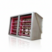
Temperature rise tests on an LV switchboard
2. Maintain your LV switchboard regularly
During installation, care should be taken to ensure that the air vents are not obstructed or limited in their effect to ensure natural ventilation of the switchboard.
The cleanliness of the air vents but more generally of the electrical panel should be periodically checked to avoid any degradation of the intrinsic qualities of the assembly. In addition, the forms of internal separation will not be removed, they are the ones which ensure the protection of the personnel during the thermography and maintenance campaigns.
3.Monitor heat build-up by thermography
Thermography campaigns require going as close as possible to, and aiming at, live components. In doing so, the operator will take more risks than during the operation of his switchboard.
Inspection of the cable terminations is a must. Easy access and the width of the cable sheath are criteria to be considered. The position and shape of the downstream power connections are elements that can bring a increased ease of this operation.
For feeders, the possibility of opening the front opening drawer allows all components and all clamping points of the drawer to be seen.
If this option was not chosen at the time of purchase, the starter may have been fitted with a sighting window, which will nevertheless allow some thermal readings to be taken, but in a much smaller sighting area.
Thermographic sighting
The main busbar, which is often placed in the upper position of the switchboard, can also be examined. The main purpose is to check the temperature at the busbar joints and connections. The fewer they are, the fewer points to be monitored.
The roof of the electrical panel must meet certain safety requirements:
Easy removal of the sheet metal
Equipment of removable sheets with captive bolts
Presence of forms of protection
By its’ design, the assembly must facilitate this operation, which is often uncomfortable to carry out because it is high up and close to live elements.
When choosing the LV switchboard, it is therefore important to ensure that it offers a safe and easy access solution for this type of operation.
The power connections on the incoming circuit breaker(s) are also often difficult to access. This is particularly true for switchboards with cable connections from the front. In this case, permanently readable infrared sensors can be offered.
Points of Vigilance for Sighting Devices without Dismantling
For sighting devices without dismantling (arc-proof windows, large arc-proof windows, grids), the solution must allow measurements to be taken without opening the LV switchboard casing and guarantee the protection of the operator during the inspection, thus avoiding the need for reinforced individual protection to protect against the effects of a possible internal arc flash.
The electrical panel can be fitted with these devices on the incoming columns, to monitor the temperature at the main busbar sides or even on the fronts of some withdrawable drawers.
Focus On Viewing Solutions
Polycrystalline sightglasses are the best known solution; they are relatively expensive and offer a fairly narrow viewing surface but promise good internal arc resistance.
Larger sighting solutions of various shapes and sizes are also available. They consist of a honeycomb structure firmly attached to a plastic film. They allow a much better viewing angle and an increased inspection area. Their internal arc resistance is sufficient in many cases and their plastic film does not degrade over time, unlike polycrystals which lose their transparency over part of the spectrum as they age.
In the case of withdrawable drawers, cheaper solutions can be considered, such as the use of Plexiglas or removable metal sheets that allow partial inspection of the interior but with the appropriate individual protection. The use of front opening drawer is the solution allowing a complete inspection of the inside of the drawer but it leads to an increased risk for the operator during the measurement campaign.
Conclusion
In short, a well-designed, well maintained low-voltage switchboard and regular monitoring of its components enable you to prevent the risk of fire resulting from abnormal heating of your installation.
It should be remembered that each intervention requiring the opening of a door or front plate exposes the operator to a greater risk of internal arcing and contact with live parts.
In fact, tests on the behaviour of the electrical panel during an internal arc are always carried out with the enclosure closed and the effects of the arc on the operator are only evaluated outside the LV switchboard during internal arc conditions.
For thermography campaigns, it is necessary that the operator wears adequate individual protection and is trained to follow the appropriate methodology.
Our aim is to help your company to improve its performance.
COMECA is also a solid and innovative business partner, with strong knowledge of the major trends in the energy market such as energy efficiency, renewable energy sources and infrastructures for electric vehicles.
COMECA continues to support its established installed base all over the world, while bringing its know-how and expertise in new projects.
To support changes in energy distribution and meet customers’ needs, COMECA offers :
A « Global Solution » approach that presents important elements of differentiation
A complete and complementary range of products through its strategic core businesses, providing “package solutions”
A customised proposal, based on free choice of electrical components brands
The largest range of original manufacturer switchboards in the market
A full range of services for your existing COMECA equipment as well as for your new equipment
Power Cable Accessories
To support the installation of Low Voltage Power Cable Systems, Thorne & Derrick stock and supply an extensive range of Cable Accessories to enable to support, jointing, glanding and termination of BS5467 Armoured Cables from leading manufacturers including CMP, Cembre, Ellis Patents and 3M Electrical.
Images Courtesy of: Neil Trotter – HV & LV Cable Jointer at Northern Power Grid
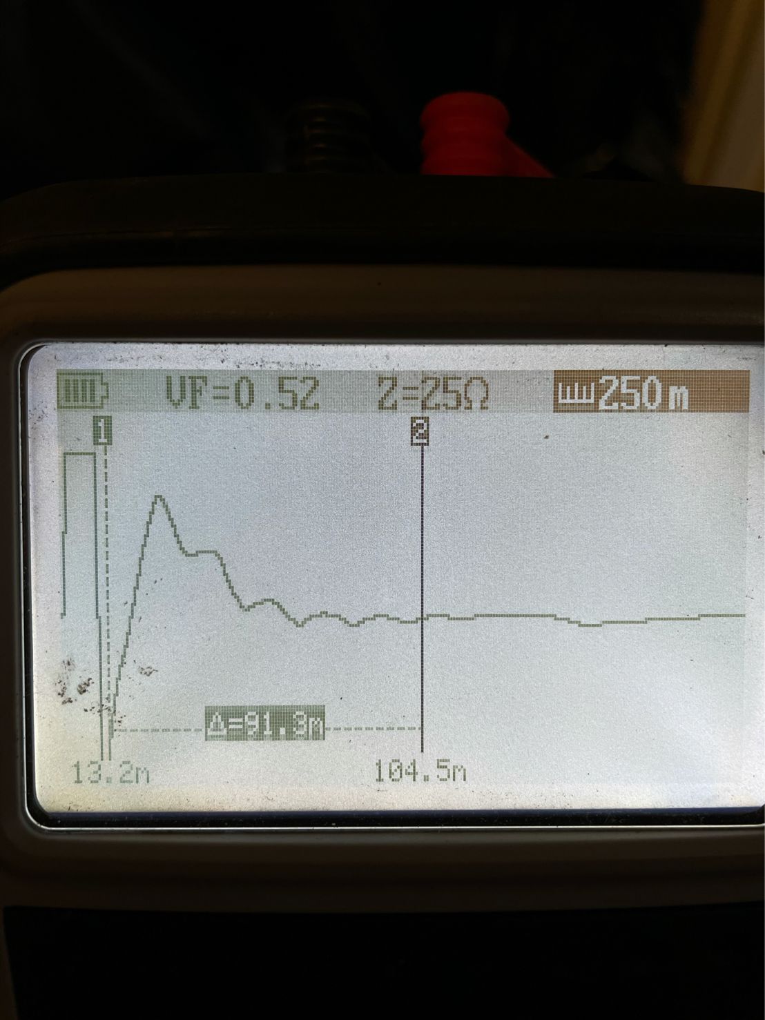
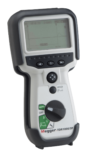
Pictured: Megger TDR1000/3P Cable Fault Location Equipment showing an LV underground mains cable fault. Fault location from substation at 104 metres. The images show an open circuit and then an issue 13 metres from point of electricity supply – this cable fault was caused by incorrect cable laying.
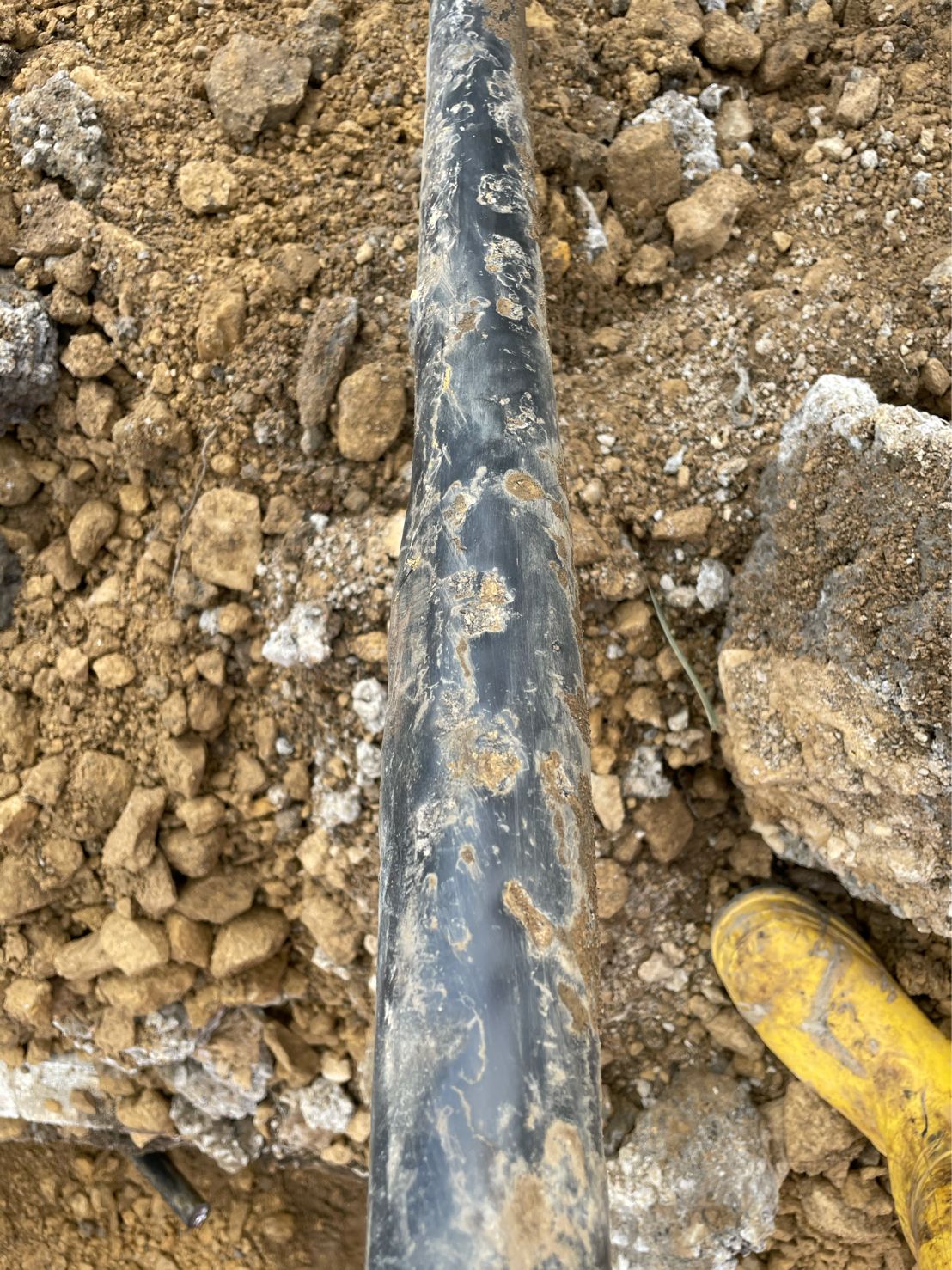
The third and fourth images show the cable outersheath has been dented by dolomite during the backfilling of the cable trench.
Megger TDR1000/3P is a compact, hand held time domain reflectometer (TDR) for locating faults on metallic cables – it has a minimum resolution of 0.1 m and a 5 km maximum range depending on velocity factor selected and cable type. The Megger range of Electrical Cable Testing & Fault Location Products are available to purchase via a network of UK Channel Partners or from established hire fleets at competitive daily/weekly hire rates, such as Sunbelt Rentals.
Handheld TDR For Troubleshooting and Locating Faults On Metallic Cables
Megger TDR1000/3P Single Channel Cable Fault Locator
Megger TDR1000/3P
handheld TDR for Power Applications
With built-in blocking filters and fused test leads, the Megger TDR1000/3P Time Domain Reflectometer is a compact, hand held time domain reflectometer for locating faults on metallic cables. It has a minimum resolution of 0.1 m/0.3 ft and a 5 km/15 kft maximum range depending on the velocity factor selected and the cable type.
Four output impedances are available (25, 50, 75, and 100 Ω) and a velocity factor between 0.2 and 0.99 will meet any cable test requirements.
Megger TDR1000 has a simple auto selection option which together with a 4 way control switch offers an intuitive operation for the user.
Adjustable display contrast
Resolution to 0.1 m
For use on Telecom TNV-3 circuit, or 150 V CAT IV power circuits
Power blocking filter not required
Environmental protection to IP54
Auto selected output impedance (between 25, 50, 75 and 100 Ω)
2 ns pulse for near end fault location
AUTO option selecting gain and pulse for each range
Display distance in metres or feet
Uses five AA (LR6) primary cells
Megger TDR1000/3P Handheld TDR
Technical Specification of Megger TDR1000/3P
Description
Time Domain Reflectometer
Part Number
1001-789
Included Accessories
Hard case, user guide CD, retractable sheath fused test lead (1 pair)
Optional Accessories
Miniature clip test lead set (1 pair), red and black probes and clips for use with all Megger TDR fused test leads, split conductor fused test lead set (1 pair)
Range
10 m, 25 m, 100 m, 250 m, 1000 m, 2500 m, 5000 m (30 ft, 75 ft, 300 ft, 750 ft, 3000 ft, 7500 ft, 15000 ft)
Accuracy
±1% of range ± pixel at 0.67 VF
[Note- The measurement accuracy is for the indicated cursor position only and is conditional on the velocity factor being correct.]
Resolution
1% of range
Input Protection
This instrument complies with IEC61010-1 for connection to live systems up to 150 V CAT IV when used with the supplied fused test lead set.
Output Pulse
5 volts peak to peak into open circuit
Gain
Set for each range with three user selectable steps (in Manual operating mode)
Velocity Factor
Variable from 0.2 to 0.99 in steps of 0.01
TX Null
Automatic
Power Down
Automatic after 5 minutes with no key press
Backlight
Stays on for 1 minute with no key press
Battery
Five LR6 (AA) type batteries, Manganese alkali or nickel metal-hydride cells
Battery Life
Up to 14 hours (Typical)
Dimensions
230 x 115 x 48 mm ( 9.0 x 4.5 x 2.0 inches)
Weight
0.6 kg (1.32 lbs)
Case
ABS
Connectors
Two 4 mm-safety terminals
Test Lead
(19 mm spaced TDR1000/3P): 1 pair 1.5 m retractable sheath, fitted with 500 mA FF HBC 1 kV 50 kA fuse
Display
256 x 128 pixel Graphics LCD
Operating Temperature Range & Humidity
-15 °C to +50 °C (5 °F to 122 °F)
Storage Temperature Range & Humidity
-20 °C to 70 °C (-4 °F to 158 °F)
Safety
When using the supplied fused test lead set this instrument complies withIEC61010-1 for connection to live systems with less than 300 V between the terminals and up to 150 V CAT IV to earth
EMC
Complies with Electromagnetic Compatibility Specifications (Light industrial) BS EN 61326-1, with a minimum performance of ‘B’ for all immunity tests
Jointers blog
Subscribe now to our POWER NEWSLETTER– a monthly email circulation packed with news, projects, videos, technical tips, training information, promotions, webinars, career opportunities and white papers.
Includes access to our popular JOINTERS BLOGwith contributions from utility professionals, linesmen and cable jointers working on MV HV EHV cables and overhead lines typically at 11kV, 33kV, 66kV and up to 132kV.
Ripley Tools is proud to announce the new Miller® MA03 Advanced Fiber Optic Preparation Kits, packed with the latest and most trusted Miller® tools and essential for any fiber cable technician.
The professional-grade, heavy-duty kits are available with either a convenient hands-free tool pouch or a durable molded case with precision cut EVA foam to keep fiber tools organized and protected.
Inside are award-winning, patent-pending Miller® tools, including the ACS+ Slitterfor Armored Cable, MB04 FTTX Drop Cable Slitter, and the MSAT® 16 Mid-Span Access Tool with 16 unique cable diameter settings. The preparation kits would not be complete without a pair of precision Miller® fiber strippers, the KS-1 Kevlar® Shears, a compact FTS Buffer Tube Scorer, and a CA Series Cable Grip Tool.
The customized Miller® storage pouch is a must for the professional with its durable 1680D high-density oxford fabric construction for added wear and water resistance.
With 13 dedicated pockets and a large internal space, there’s room to keep all the essential Miller® tools and more. It features an ergonomic carry handle and a removable long adjustable strap that doubles as a shoulder or waist strap for hands-free use. The zippered lid keeps tools protected from debris, and a heavy-duty snap keeps the top open for quick access.
For the technicians that prefer a hard-sided tool case, the new double-walled molded case is a durable and lightweight option. Its EVA foam inserts are cut to fit each of the included Miller® products, protecting the precision tools from damage and saving time looking for tools. Robust, snap-fit latches keep the kit securely closed, and the molded ergonomic handle fits comfortably in either hand.
For decades, Ripley Tools has collaborated with cable manufacturers and professional installers to design and manufacture some of the industry’s most trusted tools under the Miller® brand name.
“Ripley has been a leading provider of custom kits to telecom operator and power utility professionals for decades,” says John Jutila, CEO Ripley Tools. Jutila adds, “With advice from our current customers, we tailored a quality Miller tool assortment and custom-built case to offer to all optical cable technicians at a competitive price as a standardized field kit covering a wide variety of installation applications.”
The Miller® MA03 Advanced Fiber Optic Tool Kits are just two of the many solutions launched by Ripley Labs, the global research development and innovation center at Ripley Tools.
Miller is a Ripley brand – the full product range of high quality LV-HV cable jointing tools and wire preparation for MV-HV Power Cables, Transmission & Distribution, CATV, Electrical and Telecommunications includes Miller, Utility Tool and Cablematic.
THORNE & DERRICK
Thorne & Derrick are national distributors of LV, MV & HV Cable Installation, Jointing, Substation & Electrical Equipment – servicing businesses involved in cabling, jointing, substation, earthing, overhead line and electrical construction at LV, 11kV, 33kV, 66kV and EHV. Supplying a complete range of power cable accessories to support the installation and maintenance of low/medium and high voltage power and fibre cable systems:
Special thanks to Jonathan Hopkins (Sales Director) at S&C Electric Company for the kind permission to republish the following article.
S&C Electric Company
S&C Electric Company is a leading provider of switching, protection and control solutions for medium voltage electric power systems. Headquartered in Chicago, S&C is applying its heritage of innovation to address challenges facing the world’s power grids and thus shaping the future of reliable electricity delivery. The mission of S&C is to continually develop new solutions for electricity delivery, fostering the improved efficiency and reliability required for the intelligent grid.
Resolving Fault Current Levels
Are You Experiencing Rising Fault Current Levels On Your Overhead Network?
This could cause miscoordination and existing assets to exceed recommended symmetrical fault ratings. The Fault Tamer, Fuse Limiter from S&C Electric safely addresses this issue by combining the function of a conventional fuse with the benefits of a current limiting fuse.
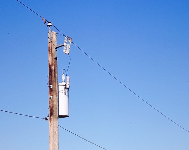
The S&C Fault Tamer combines the functionality of a conventional fuse cutoutand a backup current-limiting fuse in one powerful, easy-to-install package for the protection of new or existing overhead pole-top transformers up to 25kV.
S&C Electric Company’s Fault Tamer is manufactured in accordance with a quality system certified to ISO9001:2000.
S&C Electric Fault Tamer, Fuse Limiter Variations
98021-D, 15 kV, 110 kV BIL
98072-D, 15 kV, 125 kV BIL
98022-D, 25 kV, 125 kV BIL
98052-D, 25 kV, 150 kV BIL
98053-D, 25 kV, 150 kV BIL
S&C Electric Fault Tamer Fuse Limiter
S&C Electric Fault Tamer
product FEATURES
Fault Tamer provides many features and benefits above those of traditional fuse cutouts and cutouts used in combination with backup current-limiting fuses.
Improved Transformer Protection
Ideally suited for protecting single- or three-phase transformers through
100 kVA single-phase at 15 kV
167 kVA single-phase at 25 kV
Excellent continuous, hot-load pickup, and cold-load pickup capabilities.
High surge withstand capability. Allows arrester to be mounted on transformer tank without increasing the chance of nuisance operations due to lightning.
Energy Limitation
Minimizes equipment damage
Reduces chances of catastrophic transformer failure from internal high-current faults.
Minimizes bushing and tank damage due to external primary faults.
Improves service continuity
Provides complete coordination with upstream lateral fuses.
Provides complete coordination with substation instantaneous relay settings.
Enhances power quality
Minimizes voltage dips that can cause sensitive electronic equipment to shut down.
Operational Characteristics
Dropout action.
No parts expelled during circuit interruption.
Complies with Australian Spark Production Standard AS 1033.1-1990. Ideal for installation in areas prone to grass fires.
Handling Characteristics
Easy to install/remove using extendo stick. No climbing or bucket truck needed to re-fuse . . . unlike conventional backup current-limiting fuses.
Retrofits into all vintages of S&C Type XS Fuse Cutouts.
Operable with Loadbuster®, S&C’s Portable Loadbreak Tool.
Ratings Data
50/60-Hz Ratings
Voltage, kV
Amperes, RMS
System Class, ANSI (IEC)
System Maximum
BIL
Cont.
Interr., Sym.
60 Hz
50 Hz
Three- Phase♠
Phase-to-Neutral
Three- Phase♠
Phase-to-Neutral
15 (12)
15
8.7
15
8.7
110
20
12 000
15
8.7
15
8.7
125
25 (24)
29
16.8
26
15.1
125
29
16.8
26
15.1
150
29
16.8
26
15.1
150
22/38 (20.8/36)
–
22
–
20.8
150
♠ Also applies to phase-to-phase applications. Applications involving single-phase transformers connected phase-to-phase, as well as three-phase applications require the use of a Fault Tamer in each lead.
Operation
On low magnitude faults, just the inexpensive fuse cartridge operates — similar to a conventional fuse cutout. Fault Tamer drops open, providing visual indication that it has operated.
On high-magnitude faults, both the fuse cartridge and the backup limiter operate. The fusible element in the limiter melts in multiple locations, creating myriad series arcs that promote an initial rapid increase in arc voltage. The increased arc voltage efficiently limits current to a small fraction of the prospective peak current. Fault current is driven to zero in a controlled fashion, as the fusible element burns back and arc energy is absorbed by the surrounding sand.
Fault Tamer® Fuse Limiter | Fault Interruption — How It Works
FAULT TAMER FUSE LIMITERS
TIME-CURRENT CHARACTERISTIC (TCC) CURVES
Curve Type
Ampere Ratings
Fuse Type
TCC Number
15kV to 38kV System Voltages
Minimum Melting
3, 5, 7, 10, 15, 20
Fault Tamer
TCC Number 450-8
Total Clearing
TCC Number 450-8-3
S&C Electric Standard Speed (12kV to 22kV System Voltages)
Minimum Melting
1, 2, 3, 5, 7, 10, 15, 20
Fault Tamer
TCC Number 123-8
Total Clearing
TCC Number 123-8-3
Thorne & Derrick
T&D are Specialist Distributors to UK Distribution Network Operators (DNO’s), NERS Registered Service Providers, ICP’s and HV Jointing Contractors of an extensive range of LV, MV & HV Jointing, Earthing, Substation & Electrical Eqpt– this includes 11kV/33kV/66kV cable joints, terminations and connectors for both DNO and private network applications.
Contact our UK Power Team for competitive quotations, fast delivery from stock and technical support or training on all LV-HV products.
All international sales enquiries can be serviced and supplied by our Export Power Team.
INDUSTRIAL LABEL PRINTING SOLUTIONS When clear, durable and professional identification is required across control panels, cable systems, production facilities and industrial installations, print quality, reliability and ease of use are critical. Cembre industrial label printers are designed to support...
HIGH VOLTAGE JUNCTION BOXES & ENCLOSURES When high-voltage power distribution and cable termination are required, safety, enclosure integrity and long-term reliability are critical. HV Junction Boxes and Electrical Enclosures manufactured by Abtech are engineered for the safe distribution, cable termination and protection...


")


")