Copper Earthing Tapes For Down Conductors – Some General Considerations
Published 10 Jun 2018

Copper Earthing Tapes – Bare & Covered Copper Tapes
-
Uploaded by Chris Dodds - Thorne & Derrick Sales & Marketing Manager
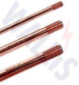
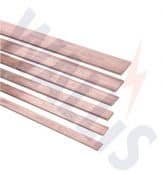
Copper Earthing Tapes
Thorne & Derrick International, a leading stockist and distributor of copper earthing tapes manufactured by AN Wallis and ABB Furse provide an overview of the role and relationship of earth tapes with respect to the design of Lightning Protection Systems in accordance with British Standard BS EN 62305.
Down conductors
Some general considerations for the use of copper earthing tapes as down conductors are as follows unless the Earthing & Lightning Protection System (LPS) is isolated:
- There should be at least two down conductors around the building
- The down conductors should be as equally spaced as possible
- Copper earth tape as down conductors should be installed at exposed corners of building
- Down conductors can be fixed to any wall or surface which is non-combustible, if the surface is combustible refer to BS EN 62305 for guidance
- Down conductors must not be sited in gutters or down pipes
- The down conductor ideally will follow the shortest and most direct path to earth
- The down conductor should as far as possible be straight and vertical
- Wherever possible avoid any re-entrant loops where this is not possible the separation distance shown in Figure 22 Is required as a minimum, if this cannot be achieved another design for the down conductor system should be considered
- A test joint should be fitted on each down conductor to enable disconnection from the earth network and provide access for earth resistance measurement and maintenance
The bottom 3 metres of the down conductor should be protected within a metal guard or PVC covering at least 3mm thick to deter vandalism and copper earthing tapes theft Figure 21. The test clamp should be fixed above the capping wherever possible Figure 21.
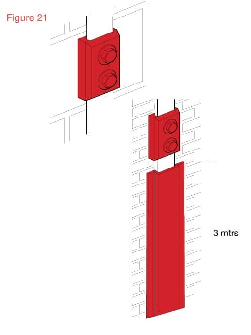
Down Conductor should be protected by metal guard of PVC covering at least 3mm thick to deter vandalism
If the air termination is a metal rod on a non conductive mast, at least one down conductor is needed for each mast.
No additional down conductors are required for masts made of metal or interconnected reinforcing steel.
If the air termination consists of one or more catenary wires at least one down conductor is needed at each supporting structure.
Positioning the down conductors
There should be multiple down conductors following the shortest possible path to earth via the conductive copper EARTH tapes.
Typical values of the distance between down conductors, subject to architectural and practical constraints are given in the table below.
Table 5.4 – Typical down conductor spacing’s and distance between ring conductors
| Class of LPS | Typical Ring Distances (M) |
| I | 10 |
| II | 10 |
| III | 15 |
| IV | 20 |
It may not be practically possible to space the down conductors exactly as required, so the spacing’s can be adjusted by ±20% but the average spacing of all down conductors must conform to the typical distances for the class of LPS.
If it is not possible to place down conductors at a side or part side of the building the down conductors that should be on that side should be placed as additional down conductors compensating for the other sides. The distance between the installed down conductors should not be less than one-third of the required down-conductor distances dependent upon the class of LPS.
Equipotential bonding to conducting parts of the structure should be performed according to BS EN 62305-3, 6.2.
The distance between the down-conductor and the internal services must satisfy the distance requirements covered in the table above.
If the separation distance required to avoid dangerous sparking between the down conductor and the internal services cannot be satisfied, the number of down conductors should be increased until the required separation distance is met.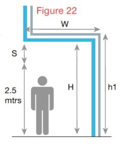
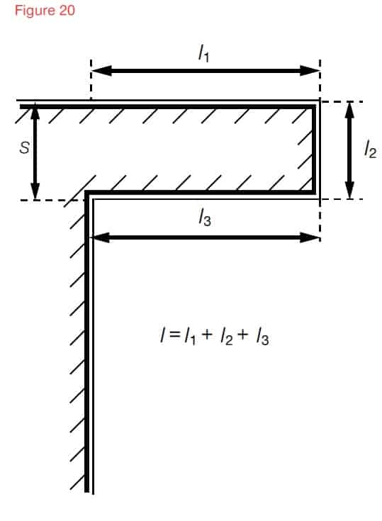
Protection on a Cantilevered Structure
There is a risk when the down conductor goes into a cantilever that a strike could flash over to this risk the separation distance, h in metres, should satisfy the the person standing underneath 2.5 as shown in figure 22. To reduce mtrs following conditions.
H > 2.5 + S
S – Is the separation distance in metres calculated.
2.5 – represents the height of a typical person with their hand in the air.
Using natural components as down conductors
The natural components can be used as down conductors provided the components comply with the requirements of BS EN 62305.
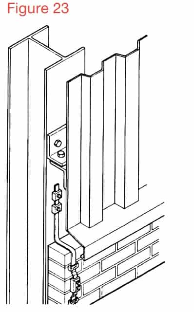
The natural components can be used provided there is electrical continuity, where the joints are tightly bolted they can be considered as electrically continuous Figure 23.
Natural components as down conductors
The facade elements, profile rails and metallic sub-constructions of facades can be used provided their dimensions conform to the requirements for down conductors and metal sheets or metal pipes, not less than 0.5mm thick.
If the metal façade of the building is to be used as the down conductor then BS 62305 offers specific guidance.
Each overlapping vertical joint at each down-conductor position should be bridged by flexible metal strapping. See Figure 24.
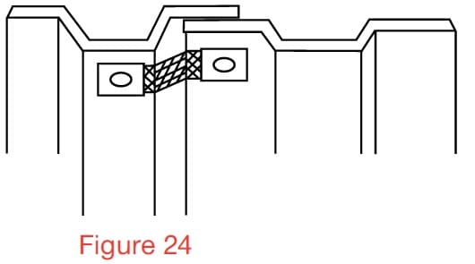
Overlapping vertical joint bridged by flexible metal strapping
Connections between the sheet metal panels should have a minimum contact surface area of 50 sqmm and be capable of be capable of withstanding the mechanical forces of a lightning discharge.
If access to the rear of the façade is not possible and the only type of fixing available for connections between facade sheets and the air termination or down-conductor tapes is pop rivets then these should be at least four 5mm diameter rivets and used on a length of conductor, such as copper earth tape, a minimum of 20mm long. (C.S.A or conductor (connection component) min 50 sqmm).
Down conductors not using the
natural components of the building
Where down conductors are installed on the building not using the natural components then consideration needs to be given to the separation distance between the internal columns and internal partition walls with conductive parts.
If these conductive columns and partitions do not satisfy the separation distance conditions they must be connected to the air termination system at roof level and to the earthing network at ground level.
What Is BS EN 62305-3:2011?
Part 3 of EN 62305 sets out all the requirements needed to protect buildings and structures against physical damage by implementing a lighting protection system (LPS). It also looks at how to protect humans and animals (living beings) against injury if they are close to an LPS. By defining these safety measures, this standard helps you to minimise damage, invest in the right electrical protection equipment and maximise hazard prevention in buildings.

Thorne & Derrick International
Contact us to discuss all your Substation Earthing, Cable Jointing & Terminating requirements for the installation of LV MV HV cables, copper earthing tapes and infrastructure including switchgear, transformers and electrical equipment up to 33kV.
Product Categories: Duct Seals | Cable Cleats | Cable Glands | Electrical Safety | Arc Flash Protection | Cable Jointing Tools | Cable Pulling | Earthing | Feeder Pillars | Cable Joints LV | Joints & Terminations MV HV

Largest UK Stocks Of Copper Earthing Tapes

Earth Rods | Earth Bars | Earth Mats | Earth Clamps – manufactured from high conductivity copper by AN Wallis and supplied by Thorne & Derrick
Further Reading
-
 Earthing & Lightning Protection Systems – AN Wallis Handbook
Size: 676.61 KB
Earthing & Lightning Protection Systems – AN Wallis Handbook
Size: 676.61 KB