Earthing | An Introduction To Earthing & Earthing Designs | Part One
Published 19 Aug 2019

An Introduction To Earthing & Earthing Designs
-
uploaded by Chris Dodds - Thorne & Derrick Sales & Marketing Manager
Earthing
Earthing & Earthing Designs
AN Wallis
In this 2 part series of articles AN Wallis introduces earthing system designs including earth electrode systems designed to safely dissipate fault current or other unwanted electrical current to the general mass of earth and also an introduction to lightning protection focusing on systems, strategies and earth terminations and networks.
An earth electrode system, professionally designed by competent Engineers, is essential to ensure the safety of personnel and the protection of equipment from dangerous voltages in and around LV MV HV substations.
AN Wallis are able to offer earth electrode system designs and associated testing services using the most up-to-date equipment and design software ‘CDEGS’. All this is carried out by competent and highly experienced Electrical Engineers and Technicians.
All design works are carried out in accordance with BS 7430:2011 — The code of practice for protective earthing of electrical installations and BS EN 50522:2010 — Earthing of power installations exceeding 1 kV a. c. amongst other specifications.
All materials supplied by A. N. Wallis have been tested and certified by an independent body ensuring the highest quality materials are made available to you.
➡ Lightning | An Introduction To Lightning Protection | Networks, Strategy & Systems | Part Two
 Earthing System Design
Considerations
 An earth electrode system should be designed to safely dissipate fault current or other unwanted electrical current to the general mass of earth. This could include power transmission and distribution, static dissipation, lightning protection as well as other associated systems.
The main considerations of an earth electrode system design should be:
- Is the system safe and suitable for the purpose for which it is intended?
- Is the system rated to carry the design fault currents?
To achieve this a number of steps are required and are detailed below.
Soil Resistivity Surveys
BS 7430:2011 states that ‘on-site resistivity testing should always be carried out prior to carrying out an earth system design and installation’.
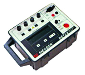
The soil resistivity survey is the first step in ensuring the correct design of an earth electrode system. It is essential that accurate measurements are taken at this stage as this data is used to determine what conductors are required in the finished earthing system to give a safe and suitable design. Corrupt data taken with inadequate test equipment could lead to a vastly over- or under-engineered solution.
AN Wallis use high specification test equipment to carry out soil resistivity testing, gaining data from tried and tested methods. This raw data is then analysed using CDEGS software to produce a representative electrical equivalent soil model which can then be used in the earthing design process.
Earth Electrode System Design

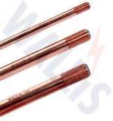
Earth Rods
There are many factors that go into producing a compliant earth electrode system design: fault current levels, fault duration, ground make up and interconnected sites are but a few.
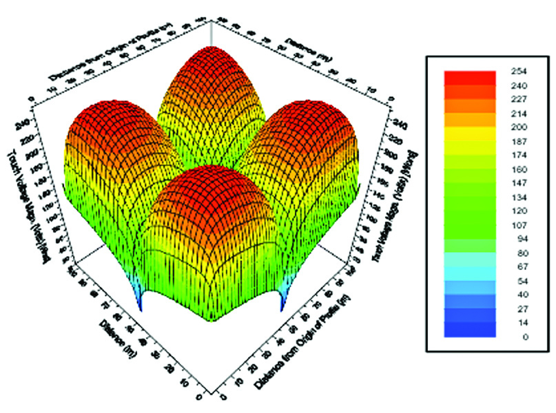
All of the parameters are analysed using the CDEGS software to ensure Touch, Step and Rise of Earth Potentials are within safe levels.
Our team of competent Engineers consider all of the above and more to ensure the final design is not only safe and suitable for its purpose, but also to ensure the system can be installed using the most economic processes giving you the most cost effective solution.
Overall System Testing
BS 7430:2011 states that ‘all work should be carried out under the control and direction of a competent person.’
AN Wallis are able to offer test and inspection services for both new and existing installations. All works are carried out in accordance with BS 7430:2011 by our trained and competent Engineers and Technicians.
The period between periodic inspection and tests can only be determined by the environment that the system is installed in, for example the harsher the environment the more regular the inspection.
Please feel free to contact us to discuss your particular requirements.

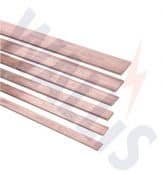
Earthing – Copper Earth Tapes | Bars | Clamps | Rods

THORNE & DERRICK
T&D are Specialist Distributors to UK Distribution Network Operators (DNO’s), NERS Registered Service Providers, ICP’s and HV Jointing Contractors of an extensive range of LV, MV & HV Jointing, Earthing, Substation & Electrical Eqpt – this includes 11kV/33kV/66kV cable joints, terminations and connectors for both DNO and private network applications.
Contact our UK Power Team for competitive quotations, fast delivery from stock and technical support or training on all LV-HV products.
Key Product Categories: Duct Seals | Cable Cleats | Cable Glands | Electrical Safety | Arc Flash Protection | Cable Jointing Tools | Cable Pulling | Earthing | Feeder Pillars | Cable Joints LV | Joints & Terminations MV HV