Lightning Protection Earthing Systems – Type A,B & Foundation Earth Electrodes
Published 10 Jul 2018

-
uploaded by - Chris Dodds (Sales & Marketing Manager Thorne & Derrick)
The following information has been provided courtesy of AN Wallis, leading UK manufacturers of Earthing & Lightning Protection Systems.
In general the Lightning Protection System (LPS) system should:
- Be an integrated system for lightning protection, power systems and telecoms systems
- Have a low overall resistance of 10 ohm’s or less
- Have an even spread of readings across all the individual earth electrode terminations to ensure as far as possible the current is evenly distributed
- Have a high resistance to corrosion
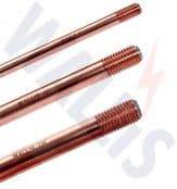
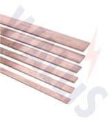
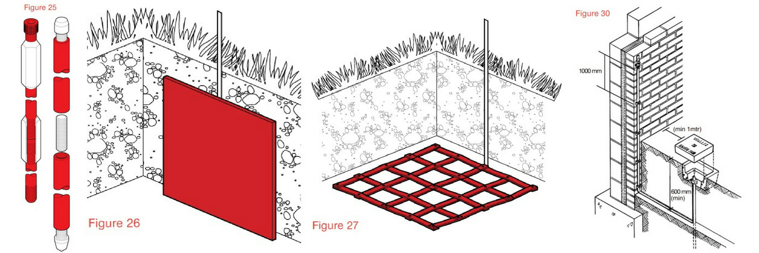
Lightning protection and earthing equipment is usually made up of earth rods either copperbonded, solid copper or stainless steel (figure 25) – also forming the earthing system are copper earth plates (figure 26), copper lattice earth mats (figure 27) or 25 x 3mm copper earth tapes.

Driven earth rods manufactured from solid copper and bonded with copper are available from stock – contact Thorne & Derrick
There are three types of LPS Earthing systems types A, B and Foundation Earth Electrodes
Type A – The conventional LPS Earthing system using
vertical or horizontal electrodes such as
copperbond Earth rods or copper tape
Type B – The ring electrode sited around the periphery of the structure
Foundation Earth Electrodes
The foundation electrode system installing the conductors in the concrete foundations of the structure.
Type A Earthing Arrangement
This is the conventional type of LPS Earthing System where earthing rods are used to form the earth electrode and usually each down conductor, such as copper earthing tapes, are connected to an earth rod.
The type A earth termination arrangement is suitable for low structures (below 20 metres in height) or an LPS with rods or stretched wires. For an isolated LPS the British Standard BS EN 62305 recommends a type B earthing arrangement where the structure is housing extensive electronic systems.
The type A arrangement uses vertical or horizontal earth electrodes. Practically it uses both connected to each down conductor, installed outside the structure (below the foundation) to be protected and housed in a plastic or concrete pit for ease of inspection (figure 30).
Lightning Protection – Copper Earthing Equipment
The minimum number of electrodes is 2.5 metres, regardless of the perimeter of the structure/class of LPS.
The minimum length of each earth electrode at the base of each down-conductor is specified in BS EN 62305 and the table below.

Minimum length l¹ of each earth electrode according to class of LPS
It is 11 for horizontal electrodes – usually copper tapes.
Or
0.511 for vertical copperbonded rods or solid copper rods. Or
>11 in the case of a lattice mat measuring the total length of the conductor in the earth mat.
Or
If copper plates are to be used the surface area of the plate should be at least equal to either.
The surface area of the length of earthing conductor that would need to be used to satisfy the requirement for a vertical electrode 0.511.
Or
The surface area of the length of earthing conductor that would need to be used to satisfy the requirement for a lattice mat electrode 11.
Or
If using vertical and horizontal electrodes, the individual earthing electrode lengths should follow the 0.511 and 11 principle respectively.
Type A earth electrodes should be installed so that the top of the earth rod is 0.5 m below the surface, this distance is to reduce the effects of step potential at ground level.
The earth rod should be housed in an inspection pit, commonly concrete or plastic for ease of inspection and registering the location during and after installation figure 30.

Full range of copper earth tapes available from stock in range of widths and thicknesses.
Type B Earthing Arrangement
The type B Earthing arrangement is most suitable for:
- Structures built on rocky ground
- Structures housing sensitive electronics/equipment
- Large structures
The type B earthing is recommended as either a ring conductor outside the perimeter of the structure which it’s recommended should be in contact with the soil for at least 80% of its total length.
The alternative is to use a foundation earth electrode which can be in a mesh form.
It is recommended that the type B earthing network whichever method is chosen should be integrated as a meshed network buried to a minimum depth of 5 rats.
The reinforced concrete floor slab can be used around the structure.
If the required resistance cannot be achieved by this method the vertical or radial earthing electrodes can be added to the network.
For ease of testing after installation an inspection pit with an earth bar should be installed where the legs of the ring and conductor routing onto the ring from the each test clamps join (figure 31).

Any internal down conductors should be connected to the internal foundation using a test clamp for ease of maintenance.
Foundation Earth Electrodes
Once all the services are connected its unlikely the installer will be able to measure the earthing resistance of the foundation earth in isolation.
The use of the foundation as an earth electrode is allowable only where the reinforcement network is below any insulating or waterproof membrane.
Where a foundation is used as an earth-termination the reinforcing bars must be clamped or welded together to ensure electrical continuity.
Alternatively an additional meshed network of conductors can be installed to ensure continuity. The additional network should be connected to the reinforcing bars by clamps or welded joints every 20 m throughout the system.
The earthing system whether using reinforcing bars or additional conductors or a combination of both must be connected to every down conductor and internal steelwork.
Internal Lightning Protection System
The internal LPS is important to fully complete the installation to fulfil the requirements of BS EN 62305.
The main reason for installing an internal LPS is to avoid any dangerous sparking within the building.
The sparking is caused by current flow and the difference in potential between internal conductive components such as steelwork and the external LPS on the outside of the building or from the use of the internal steelwork as part of the LPS.
The earthing system whether using reinforcing bars or additional conductors or a combination of both must be connected to every down conductor and internal steelwork.

THORNE & DERRICK
T&D are Specialist Distributors to UK Distribution Network Operators (DNO’s), NERS Registered Service Providers, ICP’s and HV Jointing Contractors of an extensive range of LV, MV & HV Jointing, Earthing, Substation & Electrical Eqpt – this includes 11kV/33kV/66kV cable joints, terminations and connectors for both DNO and private network applications.
Contact our UK Power Team for competitive quotations, fast delivery from stock and technical support or training on all LV-HV products.
Key Product Categories: Duct Seals | Cable Cleats | Cable Glands | Electrical Safety | Arc Flash Protection | Cable Jointing Tools | Cable Pulling | Earthing | Feeder Pillars | Cable Joints LV | Joints & Terminations MV HV