Earthing Systems Using Air Rods & Copper Tape Conductors For Roof Termination Network (BS EN 62305)
Published 11 Jun 2018


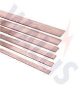
Earth Tapes – Bare & Covered Copper Tapes
-
Uploaded by Chris Dodds - Thorne & Derrick Sales & Marketing Manager
Copper Earthing Tapes
Thorne & Derrick International, a leading stockist and distributor of copper earthing tapes manufactured by AN Wallis and ABB Furse provide an overview of the role and relationship of earth tapes and air rods with respect to the design of Lightning Protection Systems for Roof Termination Networks in accordance with British Standard BS EN 62305.
Roof Termination Network
The roof termination network can be concealed below the tiles or cladding provided the air rods/strike pads protrude above the tiles or cladding (see below Figure 15).
Air rods to be selected based on the protection angle method. Strike pads should be provided in accordance with mesh spacing.
The air termination system will usually consist of air rods, flat tape conductors such as copper earthing tapes in a mesh or in some designs a catenary wire (in case of isolated LPS), there are three methods for the earthing system designer to determine the air termination system in the LPS, each is acceptable to BS EN 62305.
The earthing design comes from one of three options already detailed: the rolling sphere, protective angle or mesh alternatives, each method has different criteria for the roof network.
Wherever possible the air termination network should be located:
- At the corners of the building
- At the most exposed points of the building
- As close to the edge of the building as possible (on the parapet wall is usually as close as you can get)

The roof network should follow the most direct route with minimal bends. Where roof tiles are non-conducting the air-termination conductor may be placed either under, or over the roof tiles (over is always preferable), Where the conductor is sited below the tiles vertical finials or flat strike plates should be used These should be spaced at not more than 10 metres for air rods and 5 metres for strike plates (corresponding to class of LPS).

Roof Termination Network concealed below the tiles or cladding provided the air rods or strikes pads protrude above the tiles or cladding
In circumstances where two horizontal LPS air-termination conductors are placed parallel above the horizontal reference plane, the distance that the rolling sphere penetrates below the level of the conductors within the space between the horizontal conductors is:
Where
p = penetration distance r = rolling sphere radius
d = distance between the two parallel air terminal
rods or conductors
The penetration distance (p) should be less than the height of the air terminal/conductor above the roof surface/ reference plane, (ht), minus the height of objects to be protected.
[BS EN 62305-3, E4] p = r — (gr2 – (d/2)2

Protection For Open Roof Car Parks

Open Roof Car Park Protection
For car park structures where the roof is an open parking area (as shown in Figure 17) for cars, normally surrounded by a parapet wall, it is not advisable to have any kind of roof conductors as they are constantly being driven over and walked upon.
In these circumstances the standard allows the use of air rods on the parapet wall with a mesh on the roof hidden between the edges of adjoining slabs or bedded in the concrete with strike pads installed visible above the tarmac or concrete.
Persons and vehicles on this parking area are above the Lightning protection system and not protected from lightning.
If the top level of the car park has to be protected then air rods, catenary wire and natural masts such as lamp posts can be designed in to provide an enhanced protected area.
The step and touch potential risk on the top level of the car park can be overcome provided the roof is constructed of reinforced concrete with interconnected reinforcement steel with continuity provided by welding or clamping.
Conductive fixtures on the roof
Conductive roof fixtures such as AC units outside the zone of protection can be ignored if their height is under 300mm or if it’s under 1 mtr/2 or it’s less than 2mtr long.
Non conductive roof fixtures outside the zone can be ignored if less than 500mm in height.
A conducting fixture such as pipes or an air conditioning unit needing protection should be protected by an air termination system Figure 18. If this is not possible insulated parts, with lengths corresponding to at least twice the specified separation distance, can be installed on the conductive installations. [BS EN 62305-3, E5.2.4.2.4]

Conducting fixtures such as pipes or air conditioning units should be protected by an air termination system
When a non-conductive chimney falls outside the protective zone of the air-termination system, it should be protected by means of air-termination rods or air-termination conductors. The air termination rod on a chimney should be of such height that the complete chimney lies within the protective space of the rod.
[BS EN 62305-3, E 5.2.4.2.4]
Metal roof fixtures should be bonded to the air termination system when the necessary clearance for conformity to the separation distance cannot be maintained.
[BS EN 62305,3, E5.2.4.2.4]
Conductive electrical appliances and fittings on the roof are some of the most difficult problems facing the designer of the LPS if the requirements of BS EN 62305-3 are to fully met and the system be fully compliant. See Figure 19.
To fully comply with BS EN 62305
- Metallic roof fixtures such as air conditioning units must fall within a zone of protection offered in accordance with the angle of protection (or with the rolling sphere method)
- The units must also maintain a separation distance between the fixture and the protective air-termination equipment to prevent dangerous sparking (not required if. metallic fixtures are mechanically and electrically continuous with the structure)
In practice this is very difficult to achieve with the sometimes crowded nature of the average apartment block.
Protecting Fixtures Which Cannot Withstand Direct Strike To Its Casing
This is where the casing is not of sufficient cross-section area to comply with the thickness requirements of the standard, in these cases an air termination system should be installed to cover these units.
A separation distance should be maintained between the fixture and the air-termination to prevent sparking between the air-termination and fixture in the event of a lightning strike.
If it’s not possible to meet the requirements of BS EN 62305 the air-terminal should still be fitted and the fixture should be bonded to the conductor connecting to the air-termination.
Services from the fixture going into the building should be bonded to an equipotential bar and protected by installing a Type 1 Surge Protection Device.
Protecting Fixtures Which Can Withstand A Direct Strike To Its Casing
There is an option here to consider using the casing of the fixture itself as part of the air-termination network, the argument against is that electromagnetic effects of a direct lightning strike are likely to be greater than if the fixture was protected within the air termination network.
If the casing is used as part of the air termination network:
- Fixture should be bonded to the air-termination network when entering the building and connected to a equipotential bonding bar
- Any armouring or screening should be connected to a equipotential bonding bar and their live cores connected to the same bar using SPDs
It could be argued this is introducing the lightning strike into the building but the alternative to this approach would be to ensure that all mechanical services are insulated where they enter the building and split cables fitted with SPD’s which in the majority of cases is not practical.
Electrical Installation outside the zone of protection
If it’s just not possible to have antenna masts, satellite dishes and other electrical equipment within the zone of protection they should as a minimum be bonded into the LPS in at least two positions.
It’s unlikely all cables and other provisions will enter the building in the same place so as a all conductive sheaths and conductive mechanical protection should be bonded to the lightning protection air-termination by means of a common earth bar.
Lightning Protection for Structures Covered by Soil
Structures with a layer of soil on the roof where people are not regularly present should be fitted with a meshed air-termination system sited on top of the soil. Practically, a permanent fixed mesh could be installed. Alternatively, air termination rods sited in accordance with the rolling sphere or protective angle method and connected by a buried mesh may be used see BS EN 62305-3, E.5.2.4.2.8.
If people are likely to be present a mesh 5mtr x 5mtr should be installed beneath the soil to protect against step potentials but practically there would need to be visual warnings to the public advising against being in the area in the event of a lightning storm.
In the case of underground bunkers containing explosives an interconnected isolated LPS should be fitted as well as the mesh.
Natural Components As Part Of The Air Termination Network
Below are all permissible as part of the air termination network in the LPS according to BS EN 62305.
Metal Sheets
- Provided there is reliable and durable electrical continuity between the various parts and it’s not clad with insulation
- The thickness of the metal sheet meets the minimum dimensions shown in Table 1
- R’s permissible to use this metalwork but unlikely any designer would accept puncturing of the membrane in the event of a direct strike so as a minimum air rods should be fitted to the perimeter
- Metalwork on the roof, railings, lights, water tanks, coverings provided the metalwork meets the minimum dimensions shown in Table 1
- Even pipes and tanks carrying combustible materials can be considered provided the provided they are constructed of material with thickness not less than the standard allows (for detailed information [BS EN 623053, Annex E]
If the metallic parapet is to be used as part of the air-termination network it has to be both electrically and mechanically continuous, the minimum thickness should comply with the dimensions in Table 1 and Figure 23.
Table 1
| Material for LPS Level I To IV | Prevents puncture, hot spots or ignition (minimum thickness mm (ta) requirement | Only for metal sheets where preventing puncture, hot spots or ignition is not important. Minimum thickness mm (ta) requirement |
| Lead | – | 2.00 |
| Stainless Steel | 4 | 0.50 |
| Titanium | 4 | 0.50 |
| Copper | 5 | 0.50 |
| Aluminium | 7 | 0.65 |
| Zinc | – | 0.70 |
If a metallic roof parapet is not being used in the air-termination network then it should be bonded every 20 metres along the complete length and to each down-conductor (or at down conductor spacing).
Conductive metal objects above the roof surface and passing through the roof structure should be bonded onto the air termination network., examples of this could be a water tank with pipe work passing through the roof into the structure.

Example of Wallis Earth Bonds
Thorne & Derrick International
Contact us to discuss all your Substation Earthing, Cable Jointing & Terminating requirements for the installation of LV MV HV cables, copper earthing tapes and infrastructure including switchgear, transformers and electrical equipment up to 33kV.
Product Categories: Duct Seals | Cable Cleats | Cable Glands | Electrical Safety | Arc Flash Protection | Cable Jointing Tools | Cable Pulling | Earthing | Feeder Pillars | Cable Joints LV | Joints & Terminations MV HV

Largest UK Stocks Of Copper Earthing Tapes

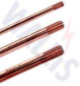
Earth Rods | Earth Bars | Earth Mats | Earth Clamps – manufactured from high conductivity copper by AN Wallis and supplied by Thorne & Derrick
Further Reading
-
 Earthing & Lightning Protection Systems – AN Wallis Handbook
Size: 676.61 KB
Earthing & Lightning Protection Systems – AN Wallis Handbook
Size: 676.61 KB