Investigating Causes of Surge Arrester Failures
Published 21 Jun 2021
*This article has been republished with the kind permission of Jon Hindle AMInstLM – Senior High Voltage M&E Installation Engineer at Grovenor Power Services*

Arresters are devices to divert lightning and switching surges and at times become overloaded to the point of failure. When this occurs, it is useful to establish the reason why the arrester or companion arresters became inoperative. This will allow maintenance staff to determine whether the end-of-life event was simply the arrester performing its protective function or if other issues need to be resolved that might be system wide. Here is where forensic analysis can play a role. This edited past contribution to INMR by Surge Arrester expert, Jonathan Woodworth, offered guidance on how to search for and identify the root cause behind an arrester’s overload.
Surge Arrester Failures
Terminal overload applies to any event where an arrester is stressed beyond its design capability. The arrester may or may not even be in one piece at that point and electrically represents an open or short circuit. While such a situation could be regarded as failure to perform its function, this is not necessarily the case.
For example, should a long-serving arrester that protects a high value asset be terminally overloaded during an overvoltage event, this can hardly be termed failure. In fact, this scenario should really be called a success.
However, if an arrester experiences a terminal overload within days of energization and with no related surges, then it is likely an indication of some form of failure. Forensic analysis is the only means to properly determine which of these scenarios applies.
In most cases, the underlying reason for conducting this type of analysis is that several arresters of similar design experience terminal overloads and the affected utility needs to find out if the problem is system wide.
If system wide and therefore a failure scenario, a different mitigation strategy would likely be needed versus a situation where it was only an isolated event. Indeed, one of the main goals of the analysis is to determine if there are separate power system issues to resolve that are not directly related to arresters.
Companion Arresters
A companion arrester is one of similar vintage and style that could be located on the same phase close to the overloaded arrester or nearby on a separate phase. It is valuable to study these during a forensic analysis and it is also preferable that the companion arrester not have been similarly overloaded or blown.
This is because an arrester that has experienced terminal overload has much of the forensic evidence obscured by the damage from the power frequency fault current. This fault current typically flows off the system to earth along the arrester and raises the temperature of various components past their melting points.
Obtaining a suitable companion arrester therefore becomes a key element in identifying the root cause of the problem.
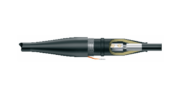
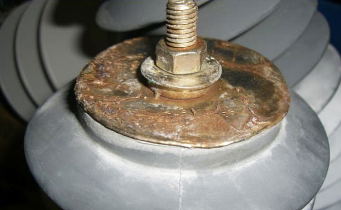
Fig. 1: Porcelain Station Arresters with internal core that has experienced a fault current event.
Relevant System Data
Collecting system data relating to the overload event is beneficial to any analysis. Such data should include:
1. System voltage;
2. Neutral configuration of the source transformer (i.e. grounded, floating, impedance grounded);
3. Magnitude of available fault current;
4. Location of the arrester;
5. Other equipment on the same phase, at the same substation or on the same line (i.e. capacitors, switches, breakers, transformers, inductors) and its status during and after the overload;
6. History at that location (e.g. other overloads during past years);
7. Switching or lightning activity at that time or during prior weeks;
8. Performance history of that arrester vintage and design applied on the system;
9. Existence of any other forensic analysis data that might offer clues to the root cause.
It is useful to avoid irrelevant or inaccurate information and rely as much as possible on the individuals directly involved in the response to the overload. The people picking up the pieces usually have the most information on the arrester’s condition following the event. It is also valuable to know if the overloaded arrester was removed only after a severe rainstorm.
Analysis
Routines to observe so as to make each analysis as effective as possible include the following:
• Gather as much system data and from as many sources as possible. Use groups of people who can offer different input on the situation.
• Inspect the arresters in question and record as much data as possible from tags, shipping documents and nameplates.
• Collect original catalogues and literature on the arrester.
• Assemble a comprehensive set of photographs of the received parts.
• Assuming a complete arrester unit (overloaded or companion) is available, perform full-scale electrical tests such as Vref, watts loss, PD and leakage.
• If sealed with an internal air volume, take a sample and conduct a gas analysis before the arrester is disassembled.
• Disassemble the arrester carefully, labelling all parts and with a camera constantly in play that’s capable of close ups with high-resolution images. Involve others in this process to ensure nothing is overlooked.
• If the parts are not too damaged, run more electrical tests and go through a checklist of clues
• Once testing and physical examination is complete, let the parts sit in place at least until all the photos have been reviewed – ideally on a big screen and with as high a magnification as possible.
• Write the forensic report, listing potential root causes. Eliminate any causes deemed unlikely based on the photos and tests.
Leading Causes & Indicators of Failure
1. Moisture Ingress
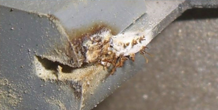
Moisture ingress is probably the leading single cause of arrester failures worldwide – both for porcelain-housed arresters and most likely for hollow core polymeric-housed arresters as well. Such ingress takes place either through the metal diaphragms that are part of the venting system or around rubber seals. In the case of polymeric arresters, moisture can also migrate directly through the rubber over time or around end seals.
Moisture ingress in a polymer arrester.
Polymeric housed arrester that experienced an external flashover and seal compromise.
Typical Causes:
Manufacturing defects, mishandling during transport or external flashover that damages the seal.
Failure Mechanism:
This tends to be a long-term failure mechanism, whereby moisture is drawn past an aged, cracked or otherwise defective seal due to the difference in pressure between the internal and external volumes of the arrester. Once the seal becomes ineffective, this pumping mechanism tends to draw in moist air during the evening, when the internal pressure is lower than the atmosphere. As moist air is exchanged between the internal volume and the atmosphere, the relative humidity on the inside reaches the same level as outside. At some point the temperature of this moist internal volume drops below the dew point and moisture condenses along the arrester’s electrically stressed internal components. This leads to dry band arcing and dielectric tracking along the wetted surfaces and will eventually result in a short circuit of the unit.
Indicators
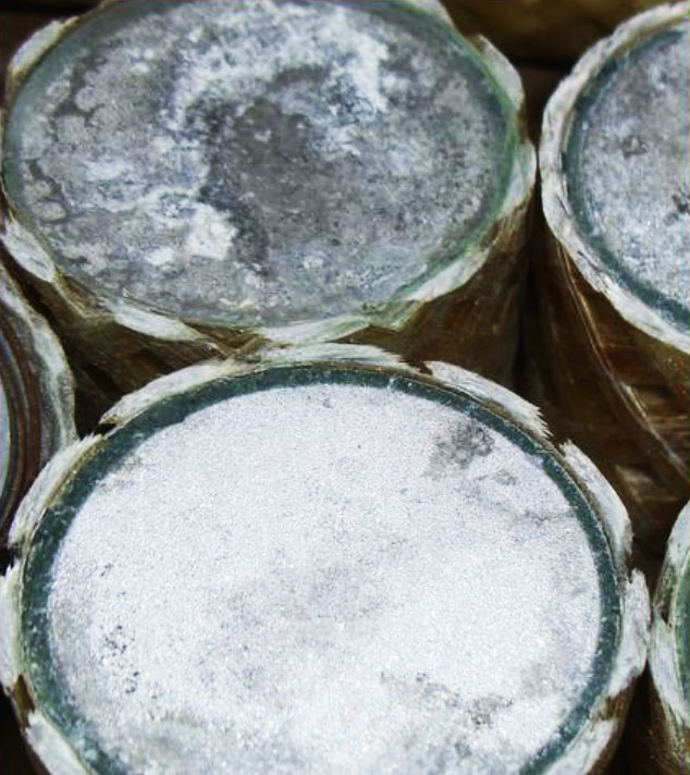
When moisture ingress is part of the failure mechanism, this is often indicated by brown rust on metal parts (or white rust on aluminium parts), increased watts loss at operating voltage, tracking along the electrically stressed components, elevated temperature in infrared image, green copper oxidation, the presence of H2O in a gas analysis or hardened rubber seals with little remaining compressive force. Old rust covered by carbon by-products of arcing indicates that the rust was there prior to failure.
Cautions
The fault current resulting from a moisture-initiated failure can look similar to a temporary voltage overload. Often, partial discharge activity within an arrester over long periods of time will result in enough ozone being produced to oxidize parts, similar to what occurs during moisture ingress.
Moisture Ingress into Polymeric Designs with No Air Volume
Although the polymeric arrester has a reputation for offering the ultimate moisture seal, this has not proven true. Polymer-housed arresters with very low internal air volume are still susceptible to moisture ingress at points where metal terminals exit the unit. It’s also a fact that silicone, EPD and other rubbers transmit water vapor at various rates. Over time, this can make the relative humidity of the entire arrester rise to the same level as the ambient atmosphere. This moisture transmission property has resulted in development of some arrester designs that are unaffected by the phenomenon. This means that any transmitted water vapor will not be allowed to condense on internal parts, gather in capillaries or condense in any form that is detrimental to the arrester’s performance.
Failure Mechanism
As with porcelain-housed arresters, this tends to be a long-term failure mechanism. If water vapor transmission is indeed the cause, this vapor collects in any small voids at the rubber/MOV disk interfaces and condenses during cool temperatures. This results in dielectric failure along this interface. Another potential failure mechanism is for water to penetrate a pressure-assisted seal and be transmitted along the fiberglass filled components in capillaries. If these capillaries become electrically stressed, it can lead to dielectric and complete failure.
All the same indicators of this problem exist as described above for porcelain-housed arresters. Red dye penetrating fluid is effective in locating ingress leaks and capillaries of this type.
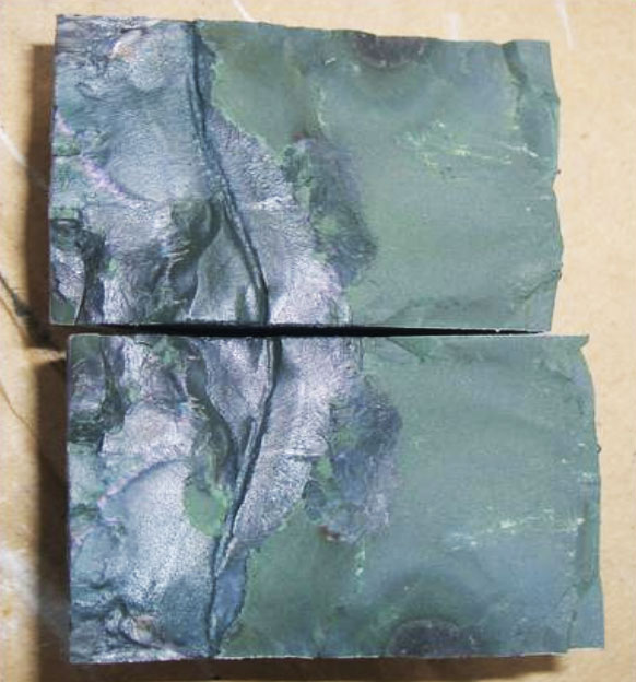
Steel component showing pre-failure (dark) and post failure (light) rust with molten aluminium on top of pre-failure rust.
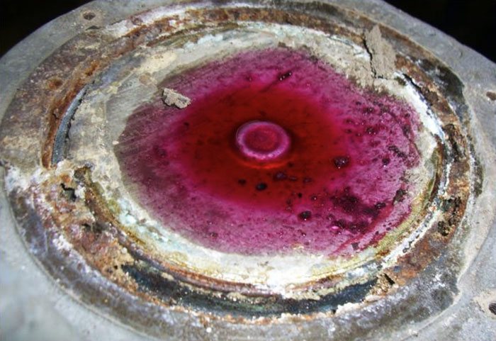
Using red dye penetrating fluid to locate a crack or leaky diaphragm.
2. External Flashover
Failure by external flashover is most common among short arresters between 2.5 kV Uc and 25 kV Uc. However, since the arrester housing is essentially a self-restoring insulator, this may or may not ever be detected. This type of situation is generally a 50 or 60 Hz event and not one associated with lightning.
Causes
Leading causes of this type of failure are either animals or severe contamination in conjunction with the presence of fog.
Failure Mechanism
If the flashover is animal-assisted, the animal is electrocuted and an external arc created over the external housing of the arrester. The fault created from the flashover will then be interrupted by some over-current device on the system. It’s even possible that the arrester is totally unaffected if the ground fault current is limited and the system can generally be re-energized right after the event.
Indicators
Arc marks on the high voltage side of the arrester and sometimes also on the ground end (mild to severe arc marks on the housing).
3. Excessive Partial Discharges
It is generally accepted that some partial discharge activity will occur inside an arrester over short periods of its life, e.g. during rain or precipitation, when there is significant radial stress due to different voltage levels on the outside surfaces compared to the dry internal surfaces. If excessive PD is present, this can lead to degradation of the disk as well as arrester dielectric leading to complete failure. This type of failure mode occurs mainly on units with significant internal air space such as porcelain and hollow core polymeric-housed (tube type) arresters. Since this is a long-term process, it may never cause the arrester to fail if the PD level remains low.
Effect of partial discharge on organic components.
Causes
Manufacturing defects, moisture ingress, mishandling, excessive contamination and moisture on the external surfaces.
Failure Mechanism
The partial discharge activity starts small and grows away from the initial point. After long exposure, the dielectrics in this area of the arrester degrade and this can lead to flashover of the electrically-stressed parts. Partial discharges can also reduce the oxygen content of the air around the disks and in some cases even change disk characteristics.
Indicators
During electrical tests, PD activity is indicated by high frequency spikes on the power frequency trace, high partial discharge readings using RIV or PD equipment and discoloration of components near edges, corners and contact points. There may also be multi-coloured growths on rubber components.
Cautions
Low levels of partial discharge over extended periods of time can corrode and oxidize metal parts of the arrester in a manner similar to moisture ingress.
4. Lightning
Lightning strokes above the design limits of an arrester can cause terminal overload of its internal dielectrics. Should an arrester experience a direct strike, the resulting failure can be immediate. However, failure can also occur later if the damage during the surge was minimal. For example, minor damage during a lightning surge can eventually trigger partial discharges that in turn lead to tracking and complete electrical failure.
Causes
Causes of such failures can include an excessive single current surge or a significant multi-stroke surge, an improper lightning duty having been specified, successive strokes to the same arrester or a TOV following a surge caused by a fault on the circuit that exceeds the arrester’s capability.
Failure Mechanism
If an arrester’s capability is exceeded by a lightning stroke, the MOV disks will initially take the surge, heat up dramatically, perhaps crack and then flashover. This will lead to a full power frequency flashover and fault current that can cover up all the evidence of the event. If the surge only causes relatively minor damage to the dielectrics of the arrester, it can fail at a later time due to other causes described above.
Indicators
If an arrester is subject to a significant surge, it is likely that its MOV material will be polarized and this is seen as conductivity in one polarity anywhere from 5 to 20% different from conductivity in the opposite polarity. If the surge has only damaged the arrester’s dielectric and ultimately leads to a long-term dielectric failure, there is no effective method to confirm this scenario. If the fault current available to a polymeric-housed arrester is low, the rubber may not show any signs of failure. Electrical tests will likely show it as shorted or nearly shorted. AC testing of MOV disks can show polarization. If the disks were subjected to a significant surge, this will be shown quite dramatically.
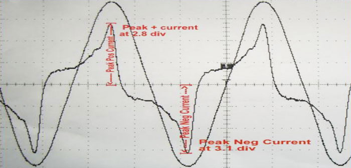
Disk showing polarization likely caused by excessive surge.
Cautions
If the fault current is of sufficient magnitude, it could cover up all evidence of lightning-induced overload.
5. Temporary Overvoltage
A terminal overload caused by a fundamental power frequency voltage beyond the design capability of the arrester is not uncommon. Arresters are designed to survive such overvoltage scenarios and, if properly dimensioned when installed, should not overload as a result. However, circuit configurations sometimes change or breakers not operate or other circuit issues produce a voltage beyond the design limit of the arrester. A TOV overload can be immediate but, unfortunately from a forensics point of view, it can also occur as a long-term failure triggered by unrelated other causes (as above).
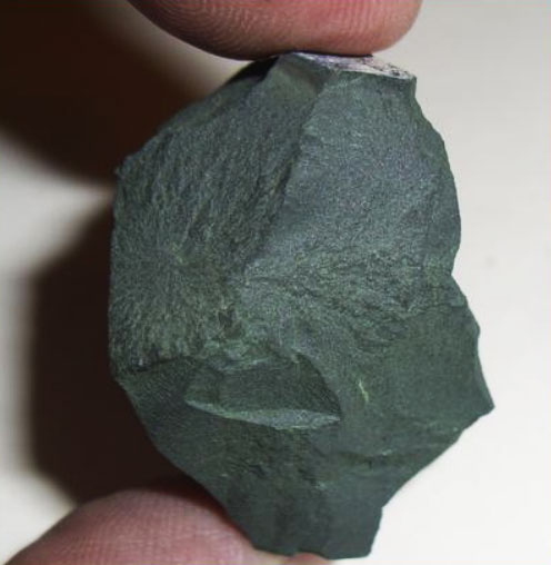
Disk cracked in two pieces from a TOV overload.
Causes
Typical causes of TOV type failure include excessive voltage rise in the unfaulted phase of a three-phase system, misapplication of the arrester, change in the system’s neutral configuration, ferroresonance, loss of neutral on a system, ageing of the disks or contact of lines with those of a higher system voltage.
Failure Mechanism
During a TOV overload, the voltage across the arrester rises to a level where the disks conduct much more than during the steady state. The conduction causes the disk to heat significantly which in turn lowers its resistance and leads to more conduction and ultimate failure. If the TOV overload is only marginal, such heating could take place over a long period.
Indicators
These include changes in disk characteristics in both polarities, cracking of a few disks in the stack, flashover of the disks, holes blown inside the polymeric housing or open vents in a porcelain-housed arrester equipped with them.
Cautions
Minimal damage to an arrester during a lightning stroke, disk aging or switching surges can all lead to a failure mode that resembles TOV overload. Here is where it is helpful to remove the faulted section of the disk and conduct AC testing on chipped sections to confirm TOV overload or not.
A chipped out section of a disk can reveal the surge history of a disk.
6. Switching Surge Overload
This overload mode can occur if arresters are subjected to surges generated from switching capacitor banks, switching or energizing long lines, switching high voltage lines or other such situations that cause the design limits of the arrester to be exceeded. Typically, this occurs only on systems above 220 kV or on systems having extremely high capacitor banks installed.
Causes
These can include re-strike or pre-strike of breakers and re or pre strike of capacitor switches.
Failure Mechanism
Essentially the same as for lightning mechanisms.
Indicators
Numerous small holes in the aluminium electrode of the disks, generally around the circumference of the disk electrode. Another indicator is polarization of the disk at low levels.
Cautions
Fault current damage after the initial overload can disguise the real cause.
7. Ageing of Disks
Since introduction of the MOV arrester, it has been widely accepted that metal oxide disks can experience long-term changes in their characteristics, referred to as ageing. If such changes result in more losses at normal operating voltage, this can lead to arrester failure.
Cause
Mainly improper manufacturing of the disk.
Failure Mechanism
At normal operating voltages, losses gradually increase leading to internal heating. When the heat generated exceeds the arrester’s ability to dissipate it into the environment this will lead to dielectric failure and a fault on the system.
Indicators
Main indicators of this type of situation are a hot arrester at normal operating temperature, excessive electrical losses at operating voltage, disks having different losses than others in the same column, non-linearity of the disk reduced (as shown on VI trace).
8. Other Causes of Arrester Failure & Overload
• External Contamination
This type of overload can lead to external flashover of porcelain housings or excessive internal partial discharges.
• Improper Uc or TOV Rating
The installation of arresters with a Uc value lower than the steady state system voltage can result in arrester failure for what would appear to be only a minor TOV. For example, if the system has a neutral impedance installed, it requires a higher MCOV arrester than for a grounded neutral, and a fault on the system can lead to arrester failure on the un-faulted phase.
• Unbalanced Electric Field
This is a failure mode that can occur on an arrester if it is mounted too close to a ground plane of another phase. Such an improper installation situation can lead to partial discharges in the internal volume of the arrester and ultimately to failure. It can also lead to overheating of the disks due to voltage imbalance. This type of failure can also be caused by the use of inappropriate grading rings on the arrester.
• Misalignment of Disk Column
In an optimal design, the single column of disks within a porcelain-housed arrester should be centred along the length of the housing. If the disks become misaligned during transport or installation, steady state partial discharges above the acceptable level could result. Misalignment of the column during transport could also result in physical damage to the edges of the disks such that partial discharge or even a flashover occurs readily during a lightning event.
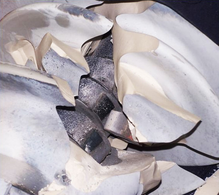
A porcelain arrester broken open for analysis. Note the disks show flashover.
• Improper Spring Pressure
If the spring within an arrester is not of sufficient pressure, the disk column can more easily become misaligned. This type of defect can lead to the same misalignment issue discussed above. Similarly, if the pressure of the spring is too low, partial discharges or damage to disks can occur more easily during a surge event.
• Mechanical Stress
Should an arrester be mounted in such a way that it is subject to excessive mechanical stress, it can fail over a long period of time. This misapplication generally leads to failure of the seals that in turn lead to dielectric failure of the internal components.
• Burrs
In the event that a high voltage arrester is assembled with conductive parts that have sharp points or edges, internal partial discharge can result. This design or manufacturing defect can lead to dielectric failure of the arrester.
• Insufficient Dielectric Strength
If any of the materials inside the arrester have internal or surface dielectric strength that is inadequate for the steady or impulse states, they can track or flashover. This type of manufacturing defect will be worsened by surge events.
Disassembly Considerations
The dissection of an arrester for the purposes of forensic analysis requires some familiarity with its internal components. It is therefore recommended that a drawing or sketch of all the internal components be retained before disassembly. If the arrester is porcelain-housed and cannot easily be disassembled with bolts, the best solution is to simply crack the assembly with a hammer.
While the internal spring pressure is usually not high enough to discharge the porcelain more than a few centimetres, it’s best to cover the arrester with a blanket or carton to contain all the parts.
Thick gloves should be used at all times to avoid wounds caused by porcelain shards. When dissecting a polymer-housed arrester for forensic analysis, a razor knife is usually sufficient.
![]()