Vestas turns to Nexans Windlink®
- Two-year contract will see around one million Windlink cable kits installed inside Vestas turbines across the globe
- A local extended supply chain to match Vestas global footprint while reducing carbon impact
- A successful partnership for the development of the EnVentus platform thanks to our resident engineer program
Paris, February 16, 2021 – Nexans has secured a two-year global supply contract with Vestas Wind Systems to provide around one million Windlink® cable kits for turbines destined for onshore wind farms in Europe, the US, China and Brazil. This latest agreement extends Nexans’s long-standing position as a leading global supplier for Vestas.
The Vestas contract demonstrates Nexans’s ambition to lead the change to a new world of electrification through cost-effective wind power projects. The low voltage (LV) and medium voltage (MV) cable kits will be installed inside Vestas onshore wind turbines rated at 2, 3 and 4 megawatt (MW). They will provide pre-connected, pre-tested and easy-to-fit connections for power, control and communication functions within the nacelle, tower and control panels.
The cables that Nexans is supplying to Vestas feature rubber, thermoplastic or silicone insulation according to their specific application. A significant new development for this latest contract will be the use of completely lead-free materials in the construction of Medium Voltage cables.
In addition to the performance and reliability of the Windlink cables, Vestas also appreciates the comprehensive portfolio and dedicated expertise in technical support provided by Nexans. The Windlink cable kits also benefit from a supply chain support worldwide thanks to Nexans’s manufacturing footprint in Europe, US, China and Brazil, including a recent extension of capacity in Poland and China.
Christopher Guérin, CEO of Nexans said: “We are delighted to further extend our relationship with Vestas. Our vision is to build a world that is safer, sustainable, renewable, decarbonized and accessible to everyone and the wind turbines manufactured by Vestas are a perfect fit for that vision. It is also especially pleasing that our solutions will be fitted within the next-generation EnVentus platform that enables turbines to provide more wind energy efficiently.”

Key Product Categories: Duct Seals | Cable Cleats | Cable Glands | Electrical Safety | Arc Flash Protection | Cable Jointing Tools | Cable Pulling | Earthing | Feeder Pillars | Cable Joints LV | Joints & Terminations MV

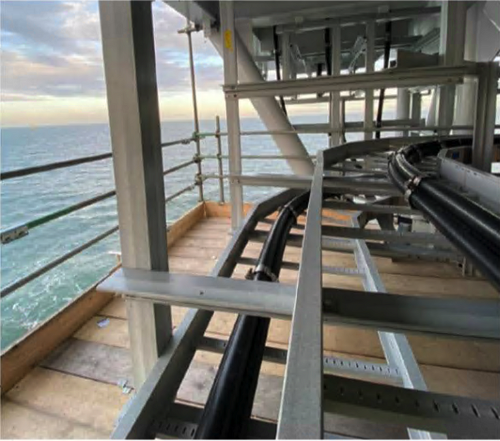
HV Cable Re-alignment
High Voltage Cable Re-alignment
Offshore Substations
- Special thanks to Geoff Briggs MIET from MGL Cable Services for the kind permission to republish this short case study in Wind Energy Network
When substation high voltage cable routing design and installation specifications do not align, MGL Cable Services bring expertise and professionalism to maintain cable integrity during the re-alignment process.
One of MGL Cable services teams recently stepped up to this challenge by demonstrating those qualities, they successfully delivered a project to re-align previously installed cables on offshore windfarm substations.
Process Preparation
As the cables were required to be removed from the high voltage switchgear this required the removal of the terminations from the switchgear, the terminations were then cleaned and protected from exposure to the harsh offshore elements.
Following the termination protection, the cables protective cable transit blocks and cable cleats were removed, this enabled the team to expertly manoeuvre the cables from the switchgear and safely suspend the cables away from the existing cable containment structure, paying careful attention to keep the cable within the manufacturer bend radius limit and protecting the cable from any sheath damage when manoeuvring to maintain cable integrity.
High Voltage Cable Re-alignment
Once the cable was safely suspended, the cables and containment structure were then modified to re-align the cable routing design and installation specifications.
The process involved manipulating the cable into the realigned cable containment structure whilst maintaining cable integrity and ensuring all terminations aligned with their respective switch gear bushings.
Once the team had effectively accomplished the re-alignment, the terminations were re-greased and re-attached to the switchgear and all fastening torque tightened to required specification. The cables were cleated into final position.
Each cable was the sheath tested to verify the cables integrity had been maintained throughout the process. The team delivered progress reports on a daily basis and sheath testing reports to ensure the client was confident MGL were delivering the high standard and workmanship required to execute the re-alignment process.
Client Feedback
Feedback from client’s representative commented on ‘genuine experts, real professionals and they were impressed with how the team handled the extreme pressures effortlessly. The team earned my highest recommendations.’
ABOUT MGL Cable Services

MGL Cable Services is a cabling focused electrical engineering company based in the North East of England. Part of the MGL Group of Companies, we have the expertise to fulfil the full scope of a large project or deliver a single service as part of a smaller scope within a large project. Our processes and procedures enable us to deliver consistent outcomes and we share our knowledge and lessons learned with clients and delivery partners.
MGL Cable Services work to high quality standards embodied within our SHEQ management systems, endorsing our Zero Harm policy to provide every client with complete peace of mind. We ensure that customer service and satisfaction are our priority and as a service provider, we work closely with the client to ensure the smooth delivery of services and projects, to specification, on time, and on budget.
Specific expertise includes High Voltage Cable Jointing up to 400kV, High Voltage Cable Testing, Fibre Optic Cable Splicing, Fibre Optic Cable Testing, Offshore Termination & Testing, Project Management, Project Support, Technical Documentation Drafting, Client Witnessing, Civil Construction and Plant, High Voltage Cable Fitters and Specialist Engineering Consultancy.

Thorne & Derrick are Specialist Distributors to the UK and international Offshore Wind & Renewable industry to provide safe and reliable
LV HV Electrical Cable & Power Distribution Systems up to 66kV – we are highly customer responsive and absolutely committed to providing a world-class service.
Contact our UK Power Team for competitive quotations, fast delivery from stock and technical support or training on all LV-HV products.
Key Product Categories: Duct Seals | Cable Cleats | Cable Glands | Electrical Safety | Arc Flash Protection | Cable Jointing Tools | Cable Pulling | Earthing | Feeder Pillars | Cable Joints LV | Joints & Terminations MV HV

MV HV Cables 11kV 33kV 66kV | Cable Joints, Terminations & Connections
Image Courtesy of: John McGaughan, Safety Manager/U.G. Cable Systems Operation Specialist-NCCER/FACTE Certified Training Instructor at Barrow Power LLC.
Pictured: Transformer Hi-Side PILC Cable Termination Chamber With Stress Cones
TECO & PILC Cable
“We only replace PILC cable that goes bad. We have about 95% in our Network system downtown. About 75% in our UCD system downtown. And about 60% at our UCD system at TIA our airport. We use P&C transition modules for take offs to our switchgears. The cable box is filled using G&W 219 insulating oil heated to 250 degrees Celsius,” John clarifies.
TECO utilise a mix of traditional PILC cable jointing accessories including varnished cambric tape from Mac Products.
Mac Products: America’s Largest Inventory of HV Cable Splicing Products
Cable Splicing Accessories
- Lead Sleeves
- Varnished Polyester Tapes
- Crepe Paper Tape
- PPC Tape
- Kraft Paper Tape
- Silicone Rubber Tape
- Compression Connectors
- Solder connectors
- Insulating Compounds
- Dielectric Fluid
- Flushing Oil
- Shielding Braid
- Live End Caps
- Cotton Tape
- Cotton Yarn
- Arc and Fireproofing Tape
- Glass Tape
- Solvent Cable Wipes
- Paper Pasters
- Abrasive Cloth
- Bar Solder
- Wire Solder
- Stearine Flux
- Rosin Flux
- Wiping Pads
- Flexible Copper Ground Strap
- Solid Copper Ground Strap
- Splicing Cement
- P & B Paint
- Lead Crotch Pieces

Jointers blog
Subscribe now to our POWER NEWSLETTER– a monthly email circulation packed with news, projects, videos, technical tips, training information, promotions, webinars, career opportunities and white papers.
Includes access to our popular JOINTERS BLOG with contributions from utility professionals, linesmen and cable jointers working on MV HV EHV cables and overhead lines typically at 11kV, 33kV, 66kV and up to 132kV.
15,000+ Subscribers. ➡ 
Image Courtesy of: Daniel Betts (33KV 11KV LV Cable Jointer at Western Power Distribution).
Pictured: 0.3 Square Inch PILC STA To 3 Core 300sqmm Wavecon Mains Transitional Straight Cable Joint
Wavecon Cable
Wavecon cable is the typical replacement for paper/lead cables in the LV distribution network.
Wavecon cable is available as “CNE” and also “SNE” – the construction is (usually) aluminium conductors (three for CNE with a fourth for a neutral in the SNE variant). The outer armouring is a copper tape/copper wire armour, providing either just the earth (SNE) or a combined neutral/earth (CNE).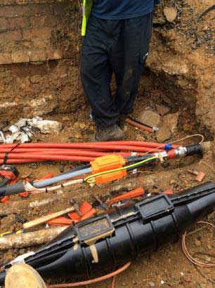
Jointing Tools
“The cable jointing tools I used to strip down the cable were a depth gauge saw to take the steel tape amours off the imperial paper insulation lead cable. Once the bitumen layers were removed with the gas torch and premane wipes I then used a hammer and insulated hack knife to remove the lead sheath down to the belt papers and the paper cores,” comments Daniel.
Jointers blog
Subscribe now to our POWER NEWSLETTER– a monthly email circulation packed with news, projects, videos, technical tips, training information, promotions, webinars, career opportunities and white papers.
Includes access to our popular JOINTERS BLOG with contributions from utility professionals, linesmen and cable jointers working on MV HV EHV cables and overhead lines typically at 11kV, 33kV, 66kV and up to 132kV.
15,000+ Subscribers. ➡
Both.
Whether lashing in a Straight 6 resin joint to power a domestic shower or jointing 110kV cables to energise Brisbane, the cable jointer must concentrate during all stages of cable stripping, measurement and joint installation.
Make an error with your measure, flirt with failure.
Of course cable failures keep cable jointers busy.
But self-inflicted cable failures caused by bad jointing and the “jointer” will soon be hanging up his crimper.
Quick joke. What’s the difference between a Jointer and a Doctor? A Doctor buries his mistakes – a jointer digs his up! Tumbleweed rolls through Blog.
Cable failures caused by poor jointing are costly.
Reputation damage plus consequential losses incurred by a power cut then multiplied by cost of the supply restoration as a formula is simply incalculable.
However, the ability to understand and apply complex mathematical formulae is a required staple of an EHV jointers skill-set.
Andrew Brezovsky is amongst many other things an EHV jointing legend and social media megastar. I suggest you Connect with Andrew on LinkedIn now – but don’t forget to hit the back button and rejoin us for a lesson in advanced cable jointing.
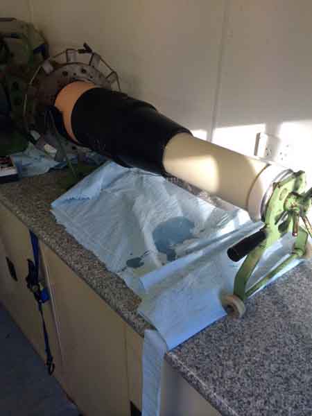
Cable Jointing Science
In todays lesson, Andrew considers the importance of the theoretical formula and the practical skill required in calculating and installing premoulded sleeves when jointing 110kV cable.
Removing the semi-conducting screen and installing the premoulded cable joint sleeve is a critical stage of jointing 110kV cables.
“So the calculation of the length of the premoulded sleeves when fitted is relying on the length of the mould, inner bore diameter of the tube, insulation diameter and the inner bore of the mould,” says Andrew.
Therefore, referring to the featured image above the calculation for the length of the premoulded sleeves is as follows:
- LS = length of cable joint mould when landed
- Z = overall length of mould as supplied
- A = inner bore diameter
- C = diameter of PVC tube
- Y = diameter of sleeve on PVC tube
- B = cable insulation diameter
Cable Jointing Art
“Here are a few shots from the mould loading process. The mould is being forced onto that PVC tube with the machine and silicone oil used as cable lubricant. The landing position is calculated individually for every cable joint to the point of a millimetre. You have to be good with your maths as the formula as you now know is complicated,” informs Andrew.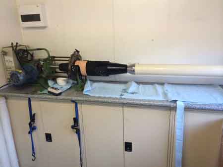
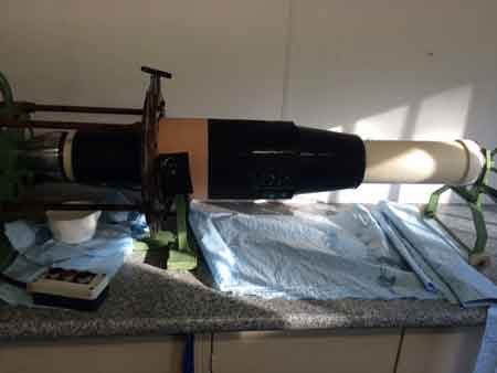 Images by EHV Cable Jointer : Andrew Brezovszky (EHV Cable Jointer – Energex Australia).
Jointers blog
Subscribe now to our POWER NEWSLETTER– a monthly email circulation packed with news, projects, videos, technical tips, training information, promotions, webinars, career opportunities and white papers.
Includes access to our popular JOINTERS BLOG with contributions from utility professionals, linesmen and cable jointers working on MV HV EHV cables and overhead lines typically at 11kV, 33kV, 66kV and up to 132kV.
15,000+ Subscribers. ➡