Choosing the Right Cable Cleat: A Practical Guide (IEC 61914 + Installation Tips)
Published 23 Feb 2026
Selecting the Right Cable Cleat: A Complete Guide
Fault restraint • IEC 61914 • Practical installation
Selecting the right cable cleat is a key part of designing and installing a reliable power distribution system. In environments such as industrial facilities, critical power and other electrical installations, cable cleats help ensure a short-circuit event does not escalate into major cable or equipment damage.
During a fault, electromagnetic forces rise rapidly and can cause cables to move violently. Correctly selected and installed cleats restrain cables during these brief but critical moments — supporting safety, equipment protection and overall system integrity.
This guide sets out practical steps to support cable cleat selection: understanding fault forces, the variables that influence cleat performance, and how to choose solutions that suit your cable formation, tray/ladder geometry and site constraints.
Fault Current Potential & Why It Drives Cleat Selection
Short-circuit events generate strong electromechanical forces between conductors. Cable cleats must restrain cables so that containment is maintained and damage risk is reduced. IEC 61914 provides methods and test requirements that help engineers assess performance against short-circuit forces. Forces are affected by peak fault current, cable spacing, cable formation (e.g., trefoil versus flat), conductor/cable diameter and cleat spacing.
Understanding these inputs helps narrow down suitable cleat types and installation approaches.
- Peak short-circuit current influences the maximum electromagnetic forces.
- Cable formation (trefoil/flat) changes how forces act between phases.
- Cable diameter & spacing affect phase separation and load conditions.
- Cleat spacing changes how much load each cleat must restrain.

LV vs MV/HV: What Changes for Cable Cleats
IEC 61914 defines LV cables as those rated up to 1.0 kV AC (or 1.5 kV DC). Above these levels, cables are treated as MV/HV for testing purposes. In practice, higher voltage systems can be associated with higher prospective fault levels, which increases the importance of verified cleat performance, correct cleat spacing and robust installation.
Key Factors That Drive Cable Cleat Selection
Cable cleat selection typically comes down to a handful of practical variables. Getting these right helps ensure compliance, performance and installability.
1) Short-circuit rating requirement
The cleat must be suitable for the prospective fault level, cable formation and cleat spacing used. Where fault levels are high, retention performance and mechanical robustness become critical.
2) Cable diameter & adjustability
Cleats must fit the actual cable OD and the selected formation. If diameters vary on-site, solutions with a wider usable diameter range can help reduce SKU complexity and simplify procurement.
3) Tray/ladder geometry
Rung/slot dimensions, access to fixings and allowable cleat spacing can dictate what works in practice. Always ensure the chosen cleat can be mounted correctly on the tray or ladder system used.
4) Installation workspace
Limited access (overhead, congested runs, risers) can make bolt tightening difficult. Consider how the cleat installs in real conditions: tooling, access underneath the rung, and whether installation must happen before or after cable pull.
5) Environment & compliance
Consider corrosion exposure, UV, temperature, and any project-specific requirements. Standards-based testing and appropriate materials (e.g., stainless steel and protective liners/coatings) are often important for longevity and cable protection.
Practical rule of thumb
Cable cleats aren’t just tidy cable management. They are a mechanical safety component designed to restrain cables during short-circuit conditions.
Start with prospective fault level and formation, then work outwards to spacing, mounting geometry and installation constraints.
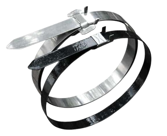
When BAND-FAST Cable Cleats Are Typically Considered
In high-fault applications and congested tray systems, installation practicality can matter as much as the short-circuit rating. BAND-FAST cable cleats are often considered where a robust retention solution is needed and where post-pull installation offers a practical advantage. Typical drivers include:
- High retention requirement within the rated test envelope
- Constrained access (overhead tray, risers, tight corridors)
- Post-pull installation preferred to avoid interfering with pulling equipment/rollers
- Reducing SKU complexity where cable diameters vary across projects
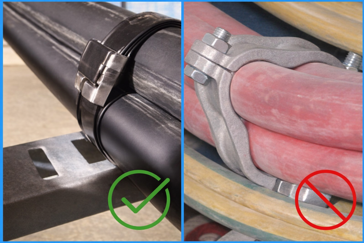
Tray Slot Width: Quick Compatibility Check
Before specifying band-style cleats, check tray or ladder slot dimensions. If rung slots are below the required width, feeding/locating the band can be inconsistent and another cleat style may be more suitable. Example minimum slot width guidance (confirm against the specific BAND-IT cleat/tooling selected):
- 5/8″ coated band: slot width ≥ 17.5 mm
- 5/8″ uncoated band: slot width ≥ 17 mm
- 3/4″ uncoated band: slot width ≥ 20 mm
Summary: How to Choose the Right Cable Cleat
Use this selection flow to keep decisions consistent:
- Define prospective fault level and verify the required short-circuit rating.
- Confirm cable formation (trefoil or flat) and actual cable outside diameters.
- Set cleat spacing aligned to test declarations and project constraints.
- Validate mounting geometry for the tray/ladder system (slots, rungs, access).
- Account for the environment (corrosion/UV/temperature) and any project standards.
- Choose an installation approach that works on site (pre-pull vs post-pull, access, tooling).
Specify BAND-IT Cable Cleats with Confidence
Tell us your cable sizes, formation, tray/ladder type and prospective fault level. We’ll help you identify a compliant, practical cable cleat solution for your installation.
Selection Support • Standards-Led Guidance • Project-Ready Supply