Trefoil Cable Cleats
Trefoil Cable Cleats | LV MV HV Cable Restraint

Manufacturers: Prysmian BICON & Ellis Patents — Cable Cleat Selection Required
Power Cables
Cleat Testing
Cleat Range
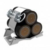
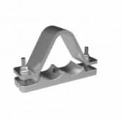
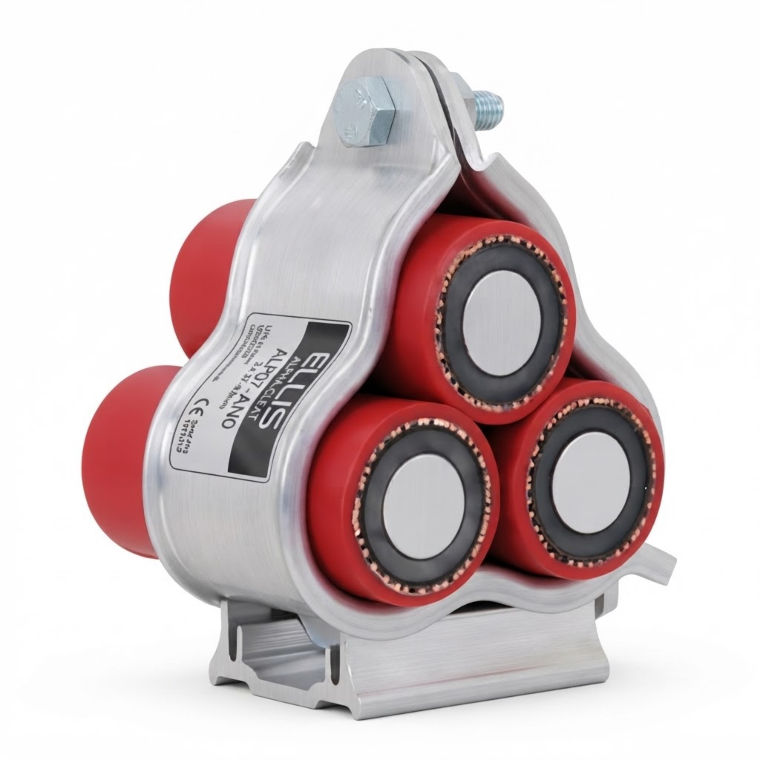
Trefoil Cable Cleats provide secure mechanical restraint for three single-core power cables installed in trefoil formation. Available from Prysmian BICON and Ellis Patents, the range includes aluminium, stainless-steel and polymeric cable cleats for LV, MV and HV cable systems.
Trefoil cable restraint for three-phase power systems | Trefoil cleats retain three single-core phase cables in a compact triangular formation. Correctly selected and spaced cleats control cable movement and help the installed cable system withstand the electromechanical forces generated during a short circuit.
Thorne & Derrick supply light-, standard- and heavy-duty trefoil cable cleats manufactured from aluminium, 316L stainless steel and polymeric materials. Selection depends on cable diameter, prospective short-circuit current, cleat spacing, support structure, fixing arrangement and environmental conditions.

Trefoil Cable Cleats for LV, MV & HV Power Cables
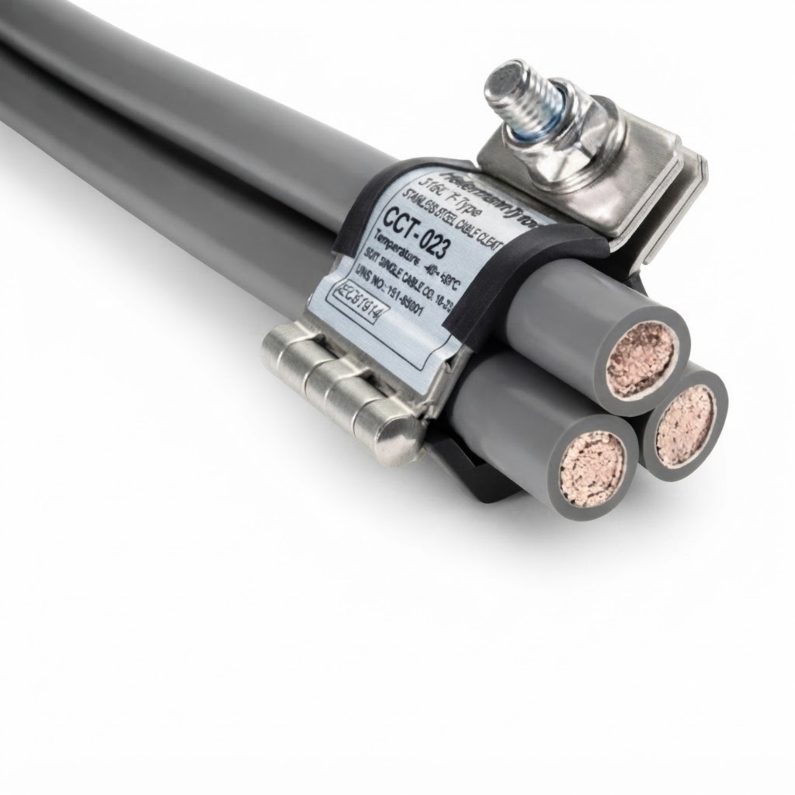
Trefoil cable cleats support and retain three single-core cables where electrical power is distributed through separate phase conductors rather than one multicore cable. When viewed in cross-section, the centres of the three cables form a substantially equilateral triangle.
Maintaining this formation helps balance the magnetic fields produced by the three phases and limits unwanted eddy-current heating in surrounding metallic components. The cleats must also restrain the high dynamic forces generated between the conductors during a three-phase short circuit.
Short-Circuit Restraint
The highest instantaneous mechanical force generally occurs during the initial asymmetrical peak of a short-circuit event. Correctly rated trefoil cleats restrain cable movement and transfer the resulting loads into the cable ladder, tray or other support structure.
Short-circuit performance cannot be selected from system voltage or conductor size alone. The cable outside diameter, peak and RMS fault current, cleat spacing, fixing method and supporting structure must all be considered.
Prysmian BICON Trefoil Cable Cleats
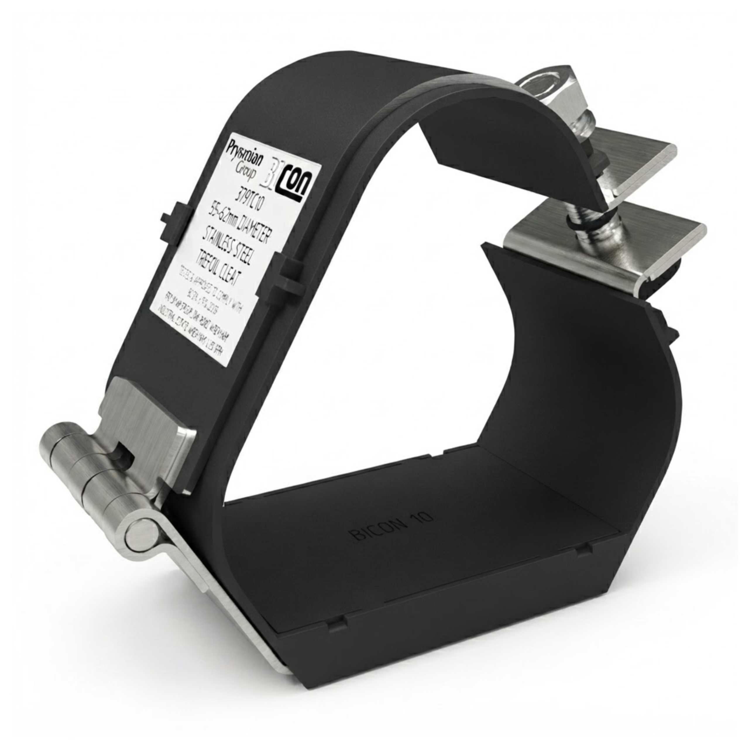
Prysmian BICON provides aluminium, stainless-steel and polyamide trefoil cleats for standard industrial installations, harsh environments and high fault-current cable systems.
Sirius 379TC stainless-steel cleats provide corrosion-resistant restraint for cable diameters from 23mm to 128mm.
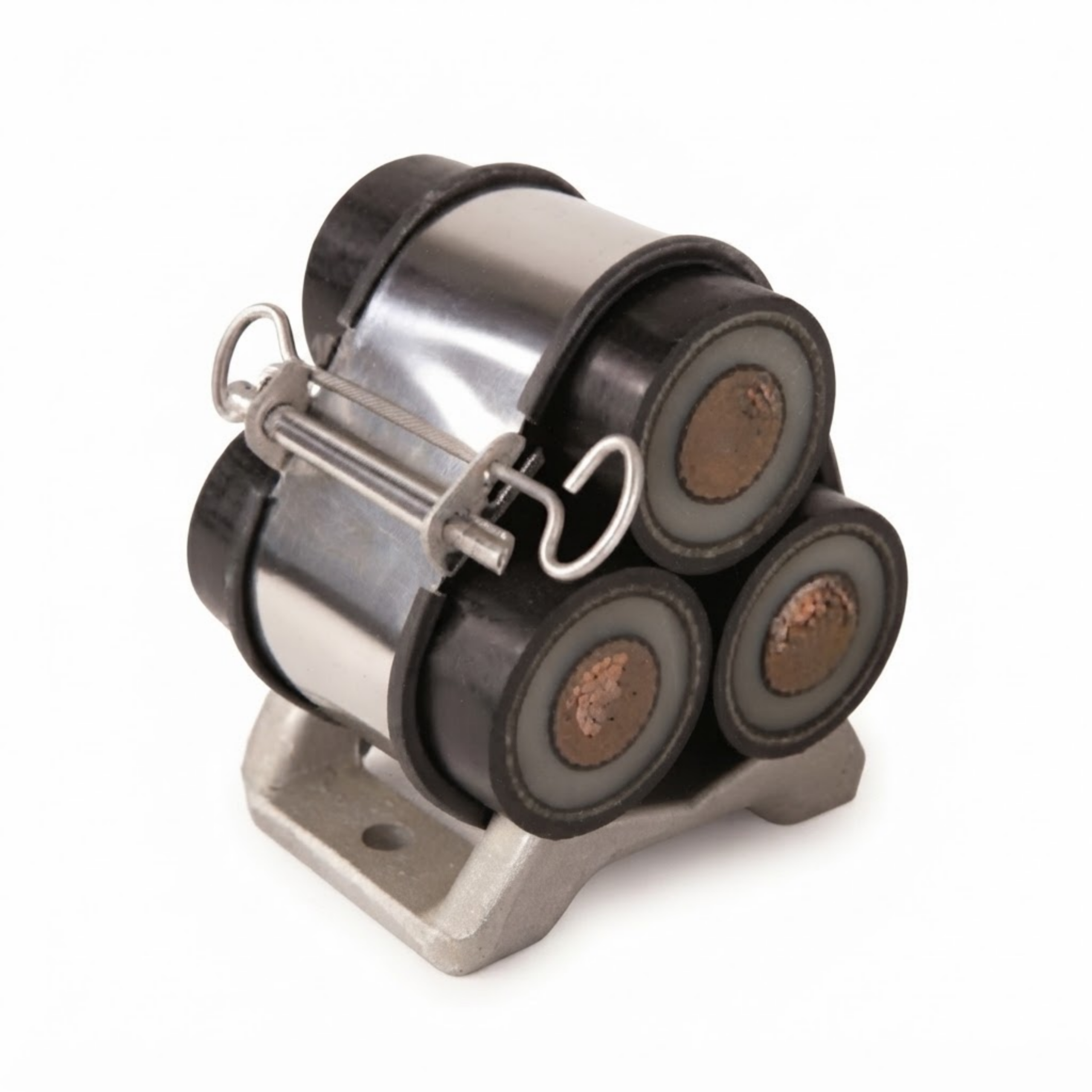
Multicleat and Multistrap 378 provides flexible trefoil restraint for cable diameters from 24mm to 145mm, with aluminium, coated-aluminium and stainless-steel base options.
Orion 376 aluminium cleats accommodate larger cables, while shaped Orion versions provide profiled restraint for demanding high-fault applications.
Libra 376AC provides compact aluminium restraint for cables from 24mm to 76mm. The Polyamide 375AB range provides a non-magnetic, halogen-free alternative.
Ellis Patents Trefoil Cable Cleats
Ellis Alpha is a light-duty compact aluminium trefoil cleat manufactured from 6000-series extruded aluminium. Aluminium and LSOH polymeric base options are available, with the polymeric base helping address galvanic-corrosion concerns.
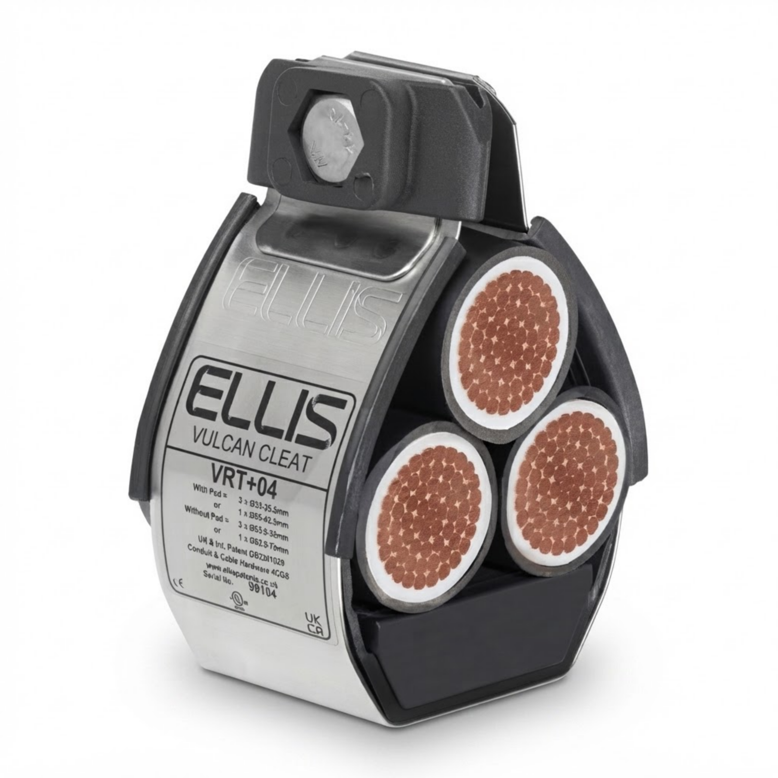
Ellis Vulcan+ is a standard-duty compact 316L stainless-steel cleat for single and trefoil cable formations. It incorporates an LSOH liner and can be fixed using one or two M10 fixings.
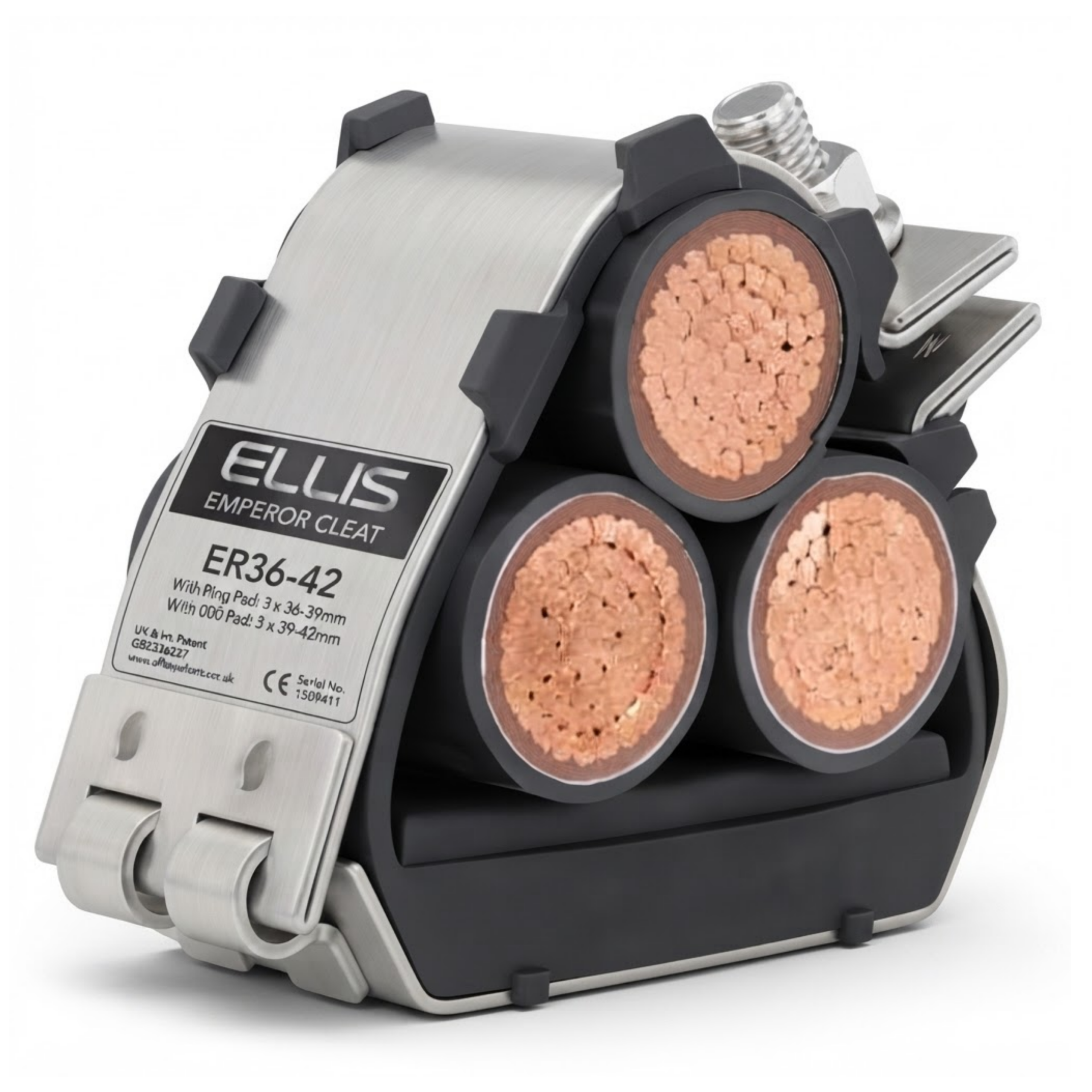
Ellis Emperor Trefoil is a heavy-duty compact 316L stainless-steel cleat for applications requiring increased short-circuit restraint. It uses an LSOH liner and A4-70 stainless-steel closure fixings.
Need help selecting the correct trefoil cable cleats? Provide the individual cable diameter, prospective fault current, required spacing, support arrangement and installation environment so our specialists can identify a suitable Prysmian BICON or Ellis Patents system.
Trefoil Cable Cleats – Technical Specifications
Important: short-circuit ratings apply only to the stated test arrangement. A result must not be transferred directly to another cable diameter, spacing or fixing configuration without engineering verification.
Trefoil Cable Cleats – Key Benefits
✔ Maintains three single-core power cables in trefoil formation
✔ Restrains cable movement during high-energy short-circuit events
✔ Supports LV, MV and HV power cable systems
✔ Choice of light-, standard- and heavy-duty cleat systems
✔ Aluminium, stainless-steel and polymeric material options
✔ Non-magnetic options help limit unwanted heating around single-core AC cables
✔ Corrosion-resistant options for outdoor and harsh environments
✔ LSOH liners and bases available on applicable products
✔ Compatible with cable ladder, cable tray and engineered support systems
✔ IEC 61914 testing supports technically verified system selection
Trefoil Cable Cleats – Applications
✔ Three single-core LV, MV and HV cables installed in trefoil formation
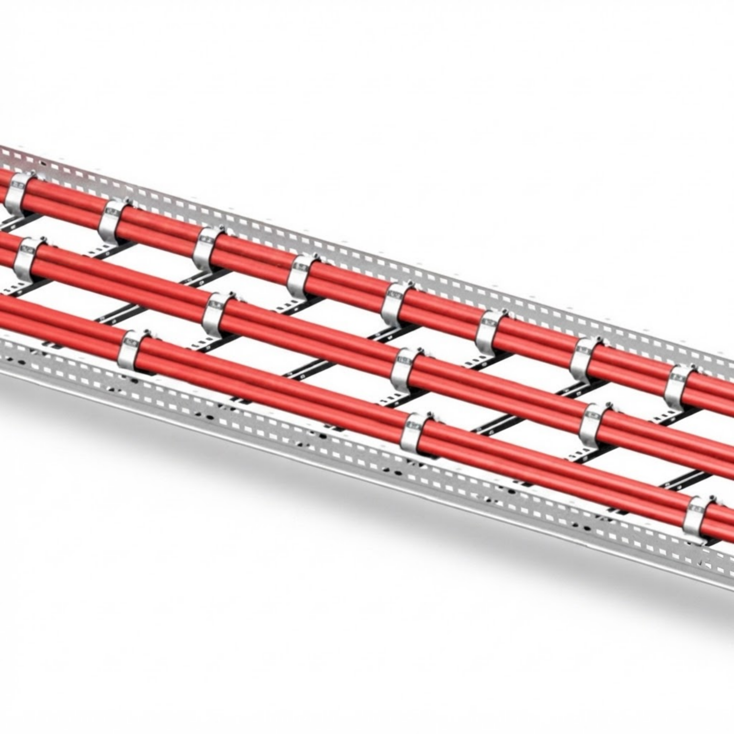
✔ Horizontal and vertical cable ladder or cable tray routes
✔ Electrical substations, switchyards and transformer connections
✔ Power-generation, transmission and distribution networks
✔ Wind, solar and battery energy storage grid connections
✔ Industrial manufacturing, process and petrochemical facilities
✔ Railways, tunnels, airports and transport infrastructure
✔ Offshore, marine and exposed outdoor cable installations
✔ Data centres, hospitals and critical-power facilities
✔ High fault-current cable routes requiring tested restraint systems
Trefoil Cable Cleats – Additional Information
Correct trefoil cable-cleat specification depends on the cable and electrical system rather than voltage designation alone. Selection must consider the actual cable outside diameter, prospective RMS and peak short-circuit currents, cable spacing, route orientation, support structure, fixing arrangement and installation environment.
✔ Cable diameter: use the measured outside diameter of each individual cable
✔ Fault current: confirm both RMS and peak prospective short-circuit values
✔ Spacing: calculate the maximum permissible interval for the selected system
✔ Support structure: verify that the ladder, tray and fixings can withstand transferred loads
✔ Route: assess straight runs, bends and vertical changes in direction
✔ Environment: consider corrosion, UV exposure, moisture, pollution and operating temperature
✔ Cable sheath: use the correct liner and tightening method to avoid sheath damage
✔ Intermediate straps: use only as part of their corresponding tested cleat system
✔ Fixings: match the bolt size, material and tightening requirements to the approved design
✔ Verification: check references, spacing and installation before the cable system is energised
 Prysmian Cable Cleats, Clamps & Cable Support CatalogueDownload