Lightning | An Introduction To Lightning Protection | Networks, Strategy & Systems | Part Two
Published 23 Oct 2019

An Introduction To Lightning Protection
-
uploaded by Chris Dodds - Thorne & Derrick Sales & Marketing Manager
Earthing
Lightning Protection
AN Wallis
In the second part of the series AN Wallis gives an introduction to lightning protection focusing on systems, strategies and earth terminations and networks.
➡ Earthing | An Introduction To Earthing & Earthing Designs | Part One
Structural Lightning Protection
Structural Lightning Protection systems are installed to minimise the risk of damage to the external & internal parts of the structure, including the electrical and electronic equipment from a lightning strike and reducing the risk of injury to humans by safely discharging the high voltage to the earth system.
The external lightning protection attracts the lightning discharge and conducts it safely to earth and the internal lightning protection, with use of transient surge protectors, minimises the damage to sensitive equipment and bonding of conductive services ensure a safe path to earth.
A complete Lightning Protection System (LPS) can only be achieved when both safety measures of Internal & External LPS are employed to the structure based on the Risk Assessment.
 JG253 - In-Situ")
Lightning Protection System (LPS) JG253 – In-Situ
Lightning Protection Strategy
The normal strategy in achieving protection is to capture the lightning at a preferred point by the use of air terminations and conducting it via low impedance down conductors and earth electrodes to a low resistance earth of less than ten ohms.
Air terminations and down conductors are spaced at regular intervals to form a mesh of conductors around the perimeter of the building and roof, known as a Faraday cage, and are joined together by specially produced damps and fixings or welding.
Lightning Protection System Design Considerations
A LPS is designed according to geographical location, local terrain, soil conditions, size and height of building, type of material used in construction, type of material stored in the building, use of building and is based on established standards for risk assessment.
The Risk Assessment needs to be carried out prior to the design of the structural LPS to determine the Class of LPL required based on the IEC / BS EN 62305 standards or internationally accepted standards.
Air Termination Networks
Based on the determined Class of LPL conductor spacing’s can be selected as identified below:
| Class of LPS | Roof Mesh Conductors W (Width – Metres) | Rolling Sphere Radius r (Radius – Metres) | Protection Angle a (Degree) | Down Conductor Spacing (Metres) |
| I | 5 x 5 | 20 | Refer to chart | 10 |
| II | 10 x10 | 30 | 15 | |
| III | 15 x 15 | 45 | 15 | |
| IV | 20 x 20 | 60 | 20 |
To calculate the areas of protection the Rolling Sphere technique can be employed. The zone of protection determined by the methods requires protection through the Roof Mesh method and Protective Angle Methods.
Roof Mesh Method — Simple and direct implementation of conductor spacing’s based on the Class of LPS, e.g. Class I LPS — Roof conductors are to be spaced in a grid of 5 x 5 metres throughout the flat roof plane.
The Protective Angle Method is based on the relativity between the height of protection required to the prescribed angle of protection in conjecture with the height to be protected which can be obtained from the chart below. Key areas or strike points need to be determined before employing the protection measure.

Class of LPS Graph
Down Conductors
Down conductor spacing has to be in accordance with the Class of LPS which is determined and to be adopted based on the table. E.g. Class I LPS — Down conductors to be spaced at every 10 metres of the structure around the periphery of the structure.
The spacing should be carried out as evenly as possible on the periphery starting at the corners and at the shortest distance to earth.
Sufficient separation distance ‘s’ need to be maintained when down conductors are placed in overhangs and care to be taken to avoid re-entrant loops.
Earth Terminations & Networks
The information contained in this section is primarily for LPS earthing.
For Earth Termination systems two basic types of earth electrode arrangements are applied. Type A earthing arrangement is suitable for low structures and existing structures. Type B earthing arrangement is usually followed throughout.
Each down conductor needs to be connected to an earth electrode to form the earthing with a minimum of two. The minimum length of earth rods that are required to be driven into ground is 2.4 metres. Earthing system contains of horizontal earth electrodes and vertical earth electrodes. Earth rods may need an earth inspection housing for periodic testing of earth resistance.
Resistance to Earth
To maintain a safe earth system, it is recommended that the earth rods to ground resistance values are less than 10 ohms. Earth resistance values are measured at low frequency.
A single earth rod may not achieve the required resistance figure and several may need to be fitted to achieve this; their combined resistance is proportional to the reciprocal of the individual rod resistances to earth.

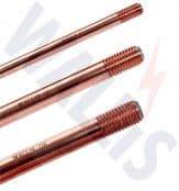
Earth Rods
This rule holds true as long as each rod is situated outside the resistance area of any other. To ensure this is the case, it is generally accepted that the minimum spacing between rods should not be less than their driven length.
The expected number of rods required to obtain a particular resistance value, e.g. ten ohms, can be roughly calculated.
To do this the soil resistivity needs to be taken into consideration. A soil resistivity test will need to be performed.
There are several methods used to obtain a lower resistance value:
- More rods can be driven. Rods can be driven deeper
- Rods of a larger diameter can be used
- Ring conductors connecting rods together underground can be used
- Where deep driving is not possible shorter rods with a larger diameter can be used; copper earth mats and earth plates can be used in place of earth rods
- A “crows foot” configuration can be used where a parallel connection is not possible
Where high resistance soil conditions are a problem soil conditioning agents can be used to backfill rod holes. Conductive concrete can be used to backfill an earth mat. Both effectively increase an electrodes cross sectional area and therefore reduce its resistance to earth.
The international standards also specify the recommended materials used for all earthing conductors and their dimensions.
Equipotential Bonding
It is common practice to use the buildings natural structural steelwork and bonding it to the LPS to further improve its ability to conduct lightning and fault currents to earth; prior permission may be required.
Joints
Joints should be mechanically effective, all joints other than welded ones are a potential discontinuity, and care should be taken to ensure contact surfaces are clean and that fixing clamps are tight and well protected from corrosion, which can occur if dissimilar metals are joined. Ideally there should be as few joints as possible in an LPS design.
Maintenance & Life of an LPS
It is important to properly maintain an LPS to ensure it retains its ability to conduct the same current carrying capacity as it did when it was originally installed. Earth rod resistances should be regularly checked.
Corrosion and fault currents can cause high resistance joints leading to overheating. However, if an LPS is correctly installed and maintained it should last for many years.
The information contained in this section is intended as a guide and should not be used to perform designs. AN Wallis does not accept responsibility for errors or omissions. Detailed information on LPS design is contained in internationally recognised European and British LPS standards.
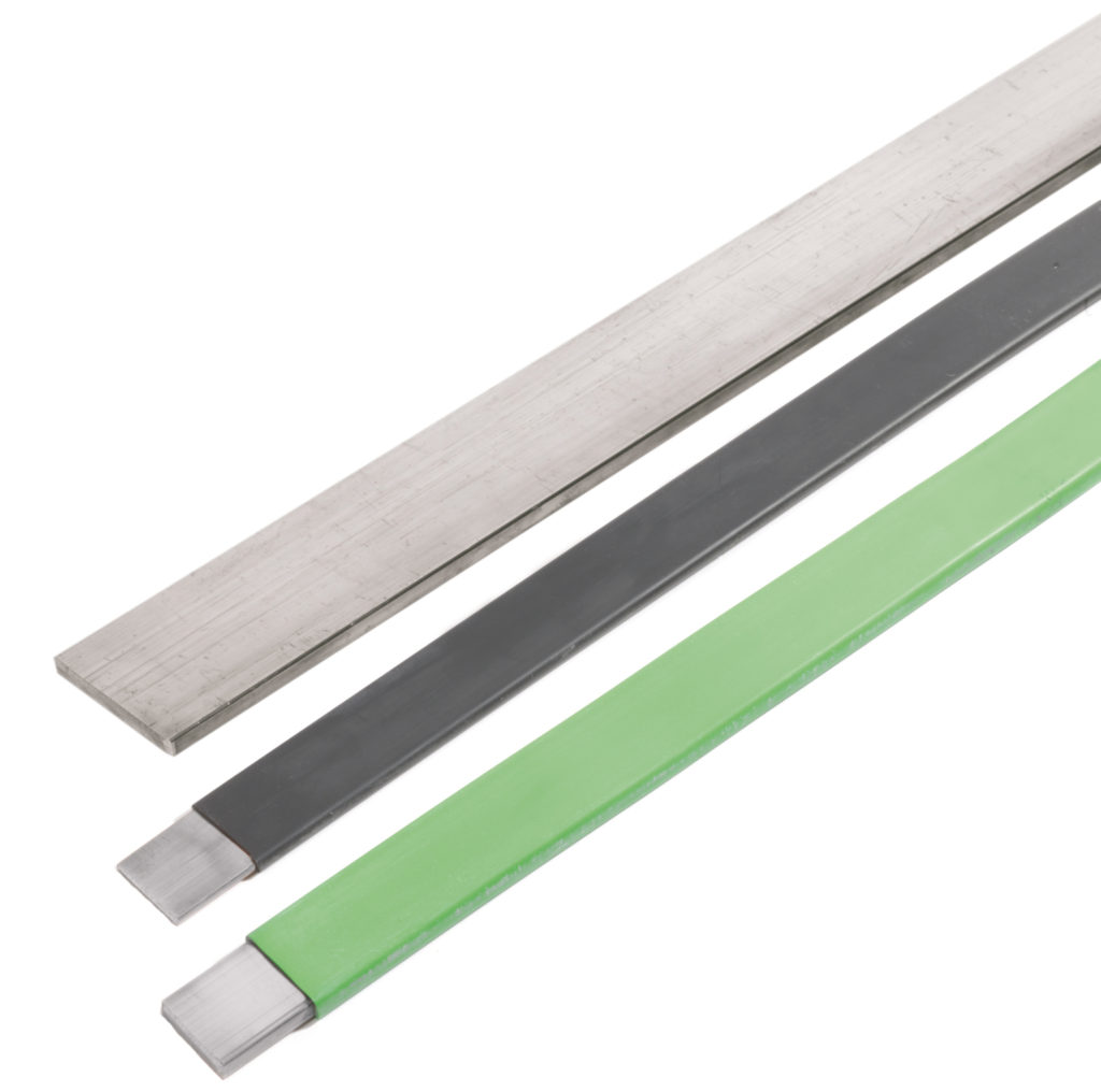

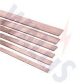
Earthing – Copper Earth Tapes | Bars | Clamps | Rods

THORNE & DERRICK
T&D are Specialist Distributors to UK Distribution Network Operators (DNO’s), NERS Registered Service Providers, ICP’s and HV Jointing Contractors of an extensive range of LV, MV & HV Jointing, Earthing, Substation & Electrical Eqpt – this includes 11kV/33kV/66kV cable joints, terminations and connectors for both DNO and private network applications.
Contact our UK Power Team for competitive quotations, fast delivery from stock and technical support or training on all LV-HV products.
Key Product Categories: Duct Seals | Cable Cleats | Cable Glands | Electrical Safety | Arc Flash Protection | Cable Jointing Tools | Cable Pulling | Earthing | Feeder Pillars | Cable Joints LV | Joints & Terminations MV HV