Ellis COL105-126 Colossus Trefoil Cable Cleats

Ellis Cable Cleats
Trefoil Cable Cleats
Cable Cleat Maximum Short Circuit Test Level 104kA
Cleat Spacing 7800mm with Intermediate Cable Straps Every 1300mm
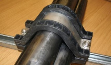
Ellis COL105-126 Colossus Cable Cleats are manufactured by Ellis Patents from heavy composite polymeric materials with integral stainless steel cleat closure – COL105-126 also includes a uniquely designed LSF LSOH (Low Smoke & Fume | Low Smoke Zero Halogen) polymer frame and able to withstand moderate levels of short-circuit according to IEC61914 calculations.
Ellis Patents COL105-126 cable cleats are suitable for securing single core power cables between 105-126mm in trefoil formation with an overall cable diameter onto cable containment including tray and ladder work in medium/high voltage power substations.
Colossus Cable Cleats form part of the Ellis Patents range of trefoil cable cleats.
ELLIS CABLE CLEAT COL105-126
TECHNICAL SPECIFICATION
- Cable Cleat Diameter Min 105mm
- Cable Cleat Diameter Max 126mm
Ellis Colossus COL105-126 Trefoil Cable Cleats 105-126mm
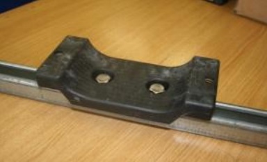
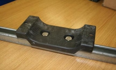
ELLIS PATENTS COL105-126 CLEAT DIMENSIONS
- Width 306mm
- Height 286mm
- Depth 150mm
- P 120mm
- 2 x M12
- Weight 3030g
Trefoil Cable Cleat Selection Table
Specification details for Ellis Patents Colossus COL105-126 cable cleat for trefoil cable applications:
| Colossus Trefoil Cable Cleat Part Number | Cable Range | Dimensions | Weight (g) | |||||
| Min Dia (mm) | Max Dia (mm) | W (mm) | H (mm) | D (mm) | P (mm) | Ø Fixing Holes | ||
| COL105-126 | 105 | 126 | 306 | 286 | 150 | 120 | 2 x M12 | 3030 |

Ellis COL105-126 Colossus Trefoil Cable Cleats
COLOssus Cable Cleats – Installation Instructions
Installation instructions for trefoil cable cleats using Colossus type cleats manufactured by Ellis Patents:
 |
 |
 |
 |
 |
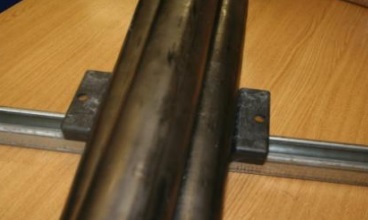
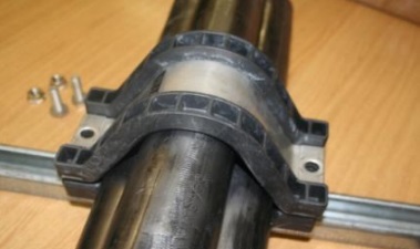
| 1.Remove the closing flange nuts and set screws. | 2. Fix the bottom half of the cleat to the support structure using M10 or M12 fixings as appropriate. | 3. Lay the LV MV HV cables in place. | 4. Fit the top half of the cleat over the cables. Secure with the M12 setscrews and flange nuts (19mm spanner/socket for setscrews, 16mm spanner/socket for flange nuts). |
5. Important. Do not over tighten the cleat. The liner should be in contact with the cable but does not need to be so tight that the cable bulges at either side of the cleat liner. |