Soil Resistivity | Why & How to Perform Soil Resistivity Surveys
Published 19 Oct 2020
Soil Resistivity Surveys
-
Special thanks to Andy Chaluda Business Development Manager - Technical Services at AN Wallis
The soil resistivity survey by AN Wallis is the first step in ensuring the correct design of an earth electrode system. It is essential that accurate measurements are taken at this stage as this data is used to determine what conductors are required in the finished earthing system to give a safe and suitable design. Corrupt data taken with inadequate test equipment could lead to a vastly over- or under-engineered solution.
Why We Carry Out Soil Resistivity Surveys
To complete an earth electrode system analysis, we need to know what the electrical properties of the ground we intend to install the earthing into.To do this, we would need to complete a soil resistivity survey of the site, or if not directly at the site, a location near to the site on a similar elevation.
How To Perform A Soil Resistivity Survey
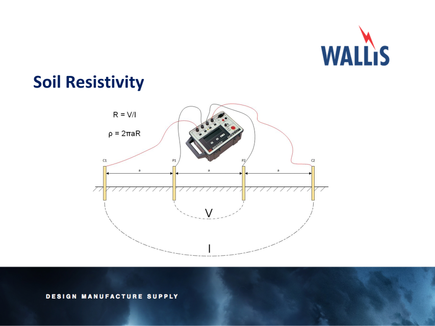
Soil Resistivity
Four probes are inserted into the ground to give a good connection. The four probes are equidistantly spaced apart from one another to the given separation distances, we tend to use the separation distances given in BS EN 50522 as a set value. The distance the probes are spaced apart, dictates the depth into the ground you are testing.
The largest separation distance would normally depend on the size of the proposed substation site, for instance a 5x5m substation may only need to have, for example a 13.5m separation distance, where as a larger substation will need larger separation distances, this would be determined by our Earthing Design professionals when attending site. We must remember that ultimately the surveys will be limited by the land available to us and can therefore take this into account should we not have sufficient space.
It may be possible to compare the derived soil model to the local geology if that is known as shown below:
| Type Of Soil | Soil Resistivity |
| Marshy Soil | 5 to 40 |
| Loam, Clay, Humus | 20 to 200 |
| Sand | 200 to 2,500 |
| Gravel | 2,000 to 3,000 |
| Weathered Rock | Mostly below 1,000 |
| Sandstone | 2,000 to 3,000 |
| Granite | Up to 50,000 |
For instance, in London, we would expect a soil model to be around 20Ω-m, as we know London is in an area of clay. If the values are dissimilar to those shown in the table extracted from BS EN 50522, we may have a problem with our surveys or the land is not natural, such as a landfill site or former quarry.
Once the first survey is complete, further surveys will be completed at different parts of the site until the data gained collates and a ‘clean’ data set is derived.
We are vigilant not to survey near buried metallic objects such as pipelines or parallel to overhead lines, as these may influence the readings taken.
Once the raw data is gained, this is then processed using the CDEGS RESAP software to gain an indicative soil model of the site and therefore completing the Soil Resistivity Survey.
Further Reading
- AN Wallis Earthing & Lightning Protection | ECA Consultant & Specifier Associate
- Earthing | An Introduction To Earthing & Earthing Designs | Part One
- Lightning | An Introduction To Lightning Protection | Networks, Strategy & Systems | Part Two
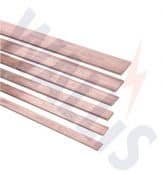
- Earth Bars | High Specification Copper Earth Bars for Lightning Protection Systems
AN Wallis
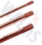
The Wallis product range includes copper earth rods (solid copper, copper bond and stainless steel types), earth bars, copper tape, earth clamps and aluminium tapes.

Specialist Distributors: LV, MV & HV Cable Jointing, Substation & Electrical Eqpt
THORNE & DERRICK are national distributors of LV, MV & HV Cable Installation, Jointing, Duct Sealing, Earthing & Electrical Equipment – we service UK and global businesses involved in cable installations, substation, overhead line and the installation of medium/high voltage cable joints and terminations at LV, 11kV, 33kV and HV.
Contact us for 3M Electrical, ABB, Alroc, AN Wallis, CATU Electrical, Cembre, Centriforce, CMP, CSD, Elastimold, Ellis Patents, Emtelle, Euromold, Filoform , Furse, Lucy Electric & Zodion, Nexans, Pfisterer, Polypipe, Prysmian, Roxtec, Sicame, WT Henley.
Further Reading
-
 AN Wallis – Earthing & Lightning Protection
Size: 3.88 MB
AN Wallis – Earthing & Lightning Protection
Size: 3.88 MB