

Fire Walls & Fire Risk Hazards Of Electrical Equipment – BS EN 61936-1 : 2010
Published 16 Apr 2019
BS EN 61936-1:2010 Fire Walls
The following information and clauses concerning fire walls is extracted from BS EN 61936-1:2010.
Power Installations Exceeding 1kV a.c. Common Rules
8.7 Protection Against Fire 8.7.1 General
Relevant national, provincial and local fire protection regulations shall be taken into account in the design of the installation.
NOTE: Fire hazard and fire risk of electrical equipment is separated into two categories: fire victim and fire origin.
Precautions for each category should be taken into account in the installation requirements.
- precautions to fire victim:
- space separation from origin of fire;
- flame propagation prevention:
physical layout of the substation,
liquid containment,
fire barriers (e.g. REI fire-resistant materials 60/90),
extinguishing system;
- precautions to fire origin:
- electrical protection;
- thermal protection;
- pressure protection;
- fire resistant materials.
Care shall be taken that, in the event of fire, the escape and rescue paths and the emergency exits can be used (see 7.1.6).
The user or owner of the installation shall specify any requirement for fire extinguishing equipment. Automatic devices to protect against equipment burning due to severe overheating, overloading and faults (internal/external) shall be provided, depending on the size and significance of the installation.
Equipment in which there is a potential for sparks, arcing, explosion or high temperature, for example electrical machines, transformers, resistors, switches and fuses, shall not be used in operating areas subject to fire hazard unless the construction of this equipment is such that flammable materials cannot be ignited by them.
If this cannot be ensured, special precautions, for example fire walls, fire-resistant separations, vaults, enclosures and containment, are necessary.
Consideration should be given to separating different sections of switchgear by fire walls. This can be achieved by means of bus ducts which penetrate the fire wall and which connect the sections of the switchgear together.
8.7.2 Transformers, Reactors
In the following sub-clauses, the word ‘transformer’ represents ‘transformers and reactors’.
For the identification of coolant types, see 6.2.2.IEC 61100 classifies insulating liquids and transformer oils according to:fire point and net caloric value (heat of combustion).
Three classes have been defined:
Class O, if the fire-point is less than or equal to 300 °C. (e.g Mineral Oil).
Class K, if the fire-point is above 300 °C. (e.g MIDEL 7131 and MIDEL eN 1024).
Class L, if the insulating liquid has no measurable fire-point.(e.g. Xiameter PMX-561).
IEC 60076-11 classifies dry-type transformers in terms of their behaviour when exposed to fire. The fire hazard associated with transformers of outdoor and indoor installations is dependent on the rating of the equipment, the volume and type of insulating mediums, the type and proximity and exposure of nearby equipment and structures.
The use of one or more recognized safeguard measures shall be used in accordance with the evaluation of the risk.
♦ IEC 60076-11:2018 Power Transformers – Part 11: Dry-type Transformers
NOTE: For definition of risk, see ISO/IEC Guide 51.
Common sumps or catchment tanks, if required, for several transformers shall be arranged so that a fire in one transformer cannot spread to another. The same applies to individual sumps which are connected to the catchment tanks of other transformers; gravel layers or pipes filled with fluid can, for example, be used for this purpose.
Arrangements which tend to minimize the fire hazard of the escaped fluid are preferred.
8.7.2.1 Outdoor Transformer Installations
The layout of an outdoor installation shall be such that burning of a transformer with a liquid volume of more than 1,000 litres will not cause a fire hazard to other transformers or objects, with the exception of those directly associated with the transformer. For this purpose, adequate clearances, G, shall be necessary.
Guide values are given in Table 3. Where transformers with a liquid volume below 1,000 litres are installed near combustible walls, special fire precautions may be necessary, depending on the nature and the use of the building.
If automatically activated fire extinguishing equipment is installed, the clearance G can be reduced.
If it is not possible to allow for adequate clearance as indicated in Table 3, fire-resistant separating walls with the following dimensions shall be provided:-
a) between transformers (see Figure 6) separating walls. For example EI 60 in accordance with the Official Journal of the European Community, No. C 62/23:
height: top of the expansion chamber (if any), otherwise the top of the transformer tank;
length: width or length of the sump (in the case of a dry-type transformer, the width or length of the transformer, depending upon the direction of the transformer);
b) between transformers and buildings separating walls. For example EI 60; if additional fire separating wall is not provided, fire rating of the building wall should be increased, for example REI 90 (see Figure 7) in accordance with the Official Journal of the European Community C 62/23.
Table 3 – Guide Values For Outdoor Transformer Clearances
| Transformer Type | Liquid Volume | Clearance G to | ||
| Other transformers or non-combustible building surface (m) | Combustible building surface (m) | |||
| Oil insulated transformers (O) | 1000 <…..< 2000 | 3 | 7.5 | |
| 2000 <…..< 20000 | 5 | 10 | ||
| 20000 <…..< 45000 | 10 | 20 | ||
| < 45000 | 15 | 30 | ||
| Less flammable liquid insulated transformers (K) without enhanced protection | 1000 <…..< 2000 | 1.5 | 7.5 | |
| ≥3800 | 4.5 | 15 | ||
| Clearance G to building surface or adjacent transformers | ||||
| Less flammable liquid insulated transformers (K) without enhanced protection | Horizontal (m) | Vertical (m) | ||
| 0.9 | 1.5 | |||
| Dry-type transformers (A) | Fire behaviour class | Clearance G to building surface or adjacent transformers | ||
| Horizontal (m) | Vertical (m) | |||
| F0 | 1.5 | 3.0 | ||
| F1 | None | None | ||
NOTE 1: Enhanced protection means:
- tank rupture strength
- tank pressure relief
- low-current fault protection
- high-current fault protection
For an example of enhanced protection, see Factory Global standard 3990 (33) or equivalent.
NOTE 2: Sufficient space should be allowed for periodic cleaning of resin-encapsulated transformer windings, in order to prevent possible electrical faults and fire hazard caused by deposited atmospheric pollution.
Three classes have been defined:
Class O, if the fire-point is less than or equal to 300 °C. (e.g Mineral Oil)
Class K, if the fire-point is above 300 °C. (e.g MIDEL 7131 and MIDEL eN 1024)
Class L, if the insulating liquid has no measurable fire-point.(e.g. Xiameter PMX-561)
8.7.2.2 Indoor Transformer Installation In Closed Electrical Operating Areas
Minimum requirements for the installation of indoor transformers are given in Table 4.
Table 4 – Minimum Requirements For The Installation Of Indoor Transformers
| Transformer Type | Class | Safeguards |
| Liquid Volume | ||
| ≤ 1000 I | El 60 respectively REI 60 | |
| ≤ 1000 I | El 90 respectively REI 90 or El 60 respectively REI 60 and automatic sprinkler protection | |
| Less flammable liquid insulted transformers (K) | Nominal power/max | |
| Without enhanced protection | (no restriction) | El 60 respectively REI 60 or automatic sprinkler protection |
| With enhanced protection | ≤ 10 MVA and UM ≤ 38 kV | El 60 respectively REI 60 or separation distances 1.5m horizontally and 1.5m vertically |
| Dry-type transformer (A) | Fire behaviour | |
| F0 | El 60 respectively REI 60 or separation distances 0.9m horizontally and 1.5m vertically | |
| F1 | Non combustible walls | |
NOTE 1: REI represents the bearing system (wall) whereas El represents the non-load bearing system (wall) where R is the load bearing capacity, E is the fire integrity, I is the thermal insulation and 60/90 refers to time in minutes.
NOTE 2: Enhanced protection means:
- tank rupture strength
- tank pressure relief
- low-current fault protection
- high-current fault protection
For an example of enhanced protection, see Factory Global standard 3990 (33) or equivalent.
NOTE 3: Sufficient space should be allowed for periodic cleaning of resin-encapsulated transformer windings, in order to prevent possible electrical faults and fire hazards caused by deposited atmospheric pollution.
Doors shall have a fire resistance of at least 60 min. Doors which open to the outside are adequate if they are of low flammability material. Ventilation openings necessary for the operation of the transformers are permitted in the doors or in adjacent walls. When designing the openings, the possible escape of hot gases shall be considered.
8.7.2.3 Indoor Transformer Installations In Industrial Buildings
For all transformers in industrial buildings, fast-acting protective devices which provide immediate automatic interruption in the event of failure are necessary.
Transformers with coolant type O require the same provisions as in 8.7.2.2.
For all other liquid-immersed transformers, no special arrangements in respect of fire.
protection are required, except for the provisions for liquid retention in case of leakage and the provision of portable fire extinguishing apparatus suitable for electrical equipment.
Dry-type transformers (A) require the selection of the correct fire behaviour class depending on the activity of the industry and on the material present in the surroundings. Fire extinguishing provisions are advisable, particularly for class F0.
NOTE: For all transformers in industrial buildings, additional fire precautions may be necessary, depending on the nature and use of the building.
8.7.2.4 Indoor Installations In Buildings Which Are Permanently Occupied By Persons
In high-voltage installations, located in public or residential buildings, special conditions shall be observed in accordance with existing standards or national regulations.
8.7.2.5 Fire in the vicinity of transformers
If there is an exceptional risk of the transformer being exposed to external fire, consideration shall be given to
- fire-resistant separating walls;
- gas-tight vessels capable of withstanding the internal pressure generated;
- controlled release of the hot liquid; fire extinguishing systems.
8.7.3 Cables
The danger of the spread of fire and its consequences shall be reduced, as far as possible, by selecting suitable cables and by the method of installation.
The cables may be assessed by reference to the following categories:
- cables without particular fire performance characteristics;
- cables (single) with resistance to flame propagation (IEC 60332 series);
- cables (bunched) with resistance to flame propagation (IEC 60332 series);
- cables with low emission of smoke (IEC 61034-1);
- cables with low emission of acidic and corrosive gases (IEC 60754-1 and IEC 60754-2);
- cables with fire-resisting characteristics (IEC 60331-21 or IEC 60331-1).
Cables in trenches and buildings shall be laid in such a way that the regulations regarding fire safety of the building are not adversely affected. For example, to avoid fire propagation, holes or cable ducts through which the cables go from one room to another shall be sealed with suitable fire proof and resistant material.
A physical separation or different routing of power circuits from the control circuits for high voltage equipment is recommended if it is necessary to preserve the integrity of the latter as long as possible following damage to the power circuits.
Where necessary, a fire alarm and fire extinguishing systems shall be installed in cable tunnels and in cable racks in the basement of control buildings.
8.7.4 Other Equipment With Flammable Liquid
For all equipment, such as switchgear which contains more than 100 l of flammable liquid in each separate compartment, special fire precautions as specified for transformers may be necessary, depending on the nature and use of the installation and its location.
Figure 6 – Separating Walls Between Transformers
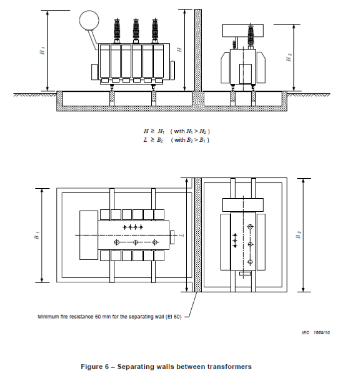
Figure 7 – Fire Protection Between Transformer & Building
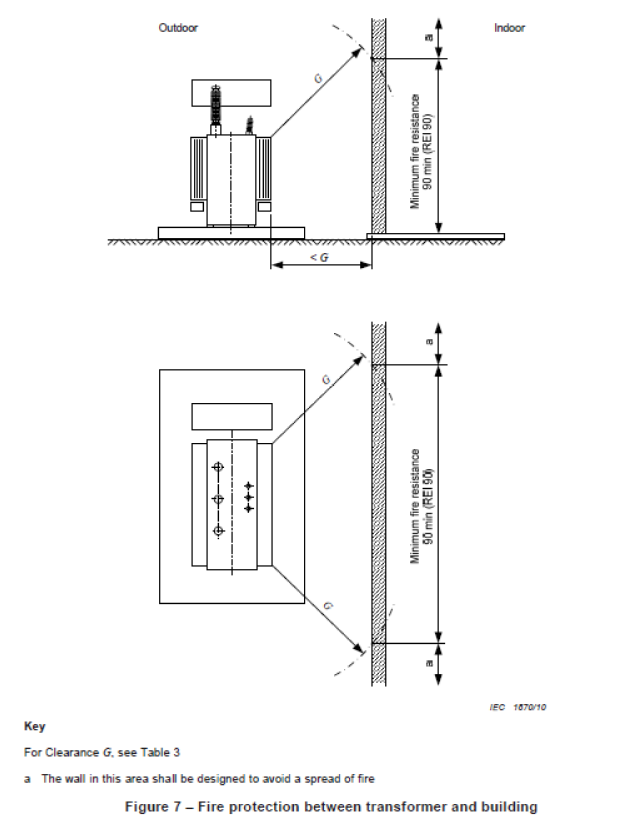
Key
For Clearance G. see Table 3
a) The wall in this area shall be designed to avoid a spread of fire
Further Reading
Transformer Oils – 11kV 33kV 66kV Substation Transformer Oil Refilling, Sampling & Analysis
Utilising Distribution Transformers To Optimise Solar
11kV Transformers | Introducing Amorphous Core HV Transformers
VIDEO How To Verify Total Absence of Voltage By The Push Of a Button
THORNE & DERRICK SPECIALIST ELECTRICAL DISTRIBUTOR
The 11kV Specialists
Thorne & Derrick distribute the most extensive range of 11kV Cable Jointing, Terminating, Pulling & Installation Equipment – we service UK and international clients working on underground cables, overhead lines, substations and electrical construction at 11kV and up to and EHV transmission and distribution voltages.
- Key 11kV Products: MV-HV Cable Joints & Terminations, Cable Cleats, Duct Seals, Cable Transits, Underground Cable Protection, Copper Earth Tapes, Cable Jointing Tools, Feeder Pillars, Cable Ducting, Earthing & Lightning Protection, Electrical Safety, Cable Glands, Arc Flash Protection & Fusegear.
- Distributors for: 3M Cold Shrink, ABB, Alroc, Band-It, Catu, Cembre, Centriforce, CMP, Elastimold, Ellis Patents, Emtelle, Furse, Lucy Zodion, Nexans Euromold, Panduit, Pfisterer, Polypipe, Prysmian, Roxtec.

LV – Low Voltage Cable Joints, Glands, Cleats, Lugs & Accessories (1000 Volts)

MV HV – Medium & High Voltage Cable Joints, Terminations & Connectors (11kV 33kV EHV)
Cable Laying – Underground Cable Covers, Ducting, Seals & Cable Pulling Equipment
T&D, CATU Electrical Safety & Arc Flash Protection Specialists for SAP’s, Linesmen, Jointers & Electrical Engineers – Largest UK Stockist
Further Reading
-
 Fire Walls & Fire Risk Hazards Of Electrical Equipment – BS EN 61936-1 : 2010
Size: 379.71 KB
Fire Walls & Fire Risk Hazards Of Electrical Equipment – BS EN 61936-1 : 2010
Size: 379.71 KB
-
BS EN 61100 : 1993 IEC 1100 : 1992 Classification Of Insulating Liquids According To Fire Point
Size: 325.54 KB


