MV Cables & Causes of MV Cable Failures
Published 10 Jan 2020

MV Cables
As well as causing disruption to power supply, MV cable accessory failures are potentially dangerous especially if they occur in public areas such as under roads or walk-ways.
Figure 46 shows the immediate result of electrical breakdown and arcing in a cable joint installed in a manhole under a walk-way.

Figure 46 – Failure of a cable joint installed in a manhole under a walk-way
The following figures illustrate some installation faults that have already resulted in accessory failure or may do so sooner or later.
Cable Joints
Figure 47 shows a cross-section cut through a heat-shrink joint. There is a large void at the 7 o’clock position. This was caused by under-heating at this part of the circumference of the joint. The installer applied most heat between 10 o’clock and 4 o’clock positions, no doubt convenient for where he was standing. Electrical stress in the void will result in partial discharges that will probably lead to breakdown of the cable joint.

Figure 47 – Air void between layers of a heat-shrink joint
Figure 48 shows removal of a strippable screen after spiral scoring. The scoring knife has been set too deep and has cut into the underlying XLPE insulation.
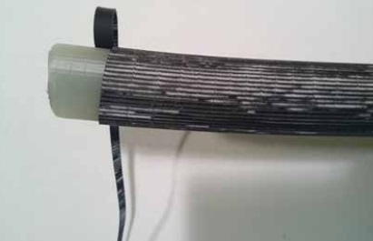
Figure 48 – Cuts into XLPE insulation caused by strippable screen scoring tool blade set too deep
Figure 49 shows a heat-shrink termination that has failed by breakdown between the cable lug and the insulation screen. Electrical tracks are visible on the insulation surface and the heat-shrink sleeve has split in a number of places due to arcing. The cause of the MV cable failure may have been under-shrinking of the heat shrink tubing and/or entry of moisture at the conductor lug.
Figure 49 – Failure of a cable termination due to electrical tracking on the insulation surface
Figure 50 shows a termination (push-on or cold-shrink type) where the cable termination body covers only part of the deep-indent conductor lug. This was probably the result of mis-placement. The cable termination must seal on to the lug barrel to prevent moisture entry. In this case the seal may have been ineffective.
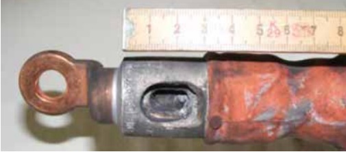
Figure 50 – Incomplete coverage of termination lug possibly allowing moisture entry
Figure 51 shows cable termination bushings on 12kV medium voltage switchgear.
The centre bushing has failed by surface breakdown after long-term partial discharge activity on its surface. The activity resulted from incomplete sealing of a heat-shrink insulating boot on to the bushing surface. Corrosion of the surrounding steelwork (caused by acidic gases generated by discharge activity) indicates that the electrical activity had been occurring for some time before complete failure.

Figure 51 – Failure of a switchgear bushing after long-term partial discharge activity
Figure 52 shows a heat-shrink termination on 3-core cable.
The individual cores may have been made to the correct length but the cable crutch position should be near the base of the cable box. The cores have been severely bent in order to make connections to the bushings. In addition, phase identification sleeves or any other covering should not be on the termination surface as they will interfere with the essential non-tracking function.

Figure 52 – Termination made without regard to dimensional instructions
Figure 53 shows what happens when the installer does not follow the installation instruction and does not remove the insulation screen. Unfortunately this indicates that he not only did not read the instruction but also does not understand the function of the screen and the fact that it is conductive. Electrical failure would have been immediate given that there is only nominal separation between phase voltage (conductor connector) and earth (insulation screen).
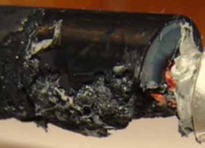
Figure 53 – Immediate failure due to insulation screen not being removed during installation
MV Cable Accessories
Thorne & Derrick, Specialist Distributors of LV HV Cable Jointing & Electrical Equipment are leading UK Suppliers of 3rd Party Type Tested MV Cable Accessories (Nexans | 3M | Pfisterer). To promote MV Cable System Integrity, we have Partnered with BASEC – British Approvals Service for Cables – their MV Cable Approval Scheme is committed to combating Non-Compliant cables entering the market-place and introducing potentially catastrophic future O&M problems.
Further Reading
- Cables | MV Paper Insulated v MV Polymeric Insulated Cables
- The Installation Site | MV Cable Joints & Cable Terminations
- First Steps | MV Joints, Jointers & Initial Considerations
- Cable Preparation | Jointing & Terminating Aspects of MV Cable Preparation
- Conductor Connectors | Crimp v Mechanical Connectors with Joints & Terminations
- Earth Bonding | Joints & Terminations & Overheating Prevention
- MV Cable Accessory Technologies | Heat Shrink, Cold Shrink & Push-on
- MV Cables | Electric Field & Stress Control

LV, MV & HV Jointing, Earthing, Substation & Electrical Eqpt
Thorne & Derrick International are specialist distributors of LV, MV & HV Cable Installation, Jointing, Duct Sealing, Substation & Electrical Equipment – servicing UK and global businesses involved in cable installations, cable jointing, substation, overhead line and electrical construction at LV, 11kV, 33kV and EHV.
THORNE & DERRICK Product Categories: Duct Seals | Cable Cleats | Cable Glands | Electrical Safety | Arc Flash Protection | Cable Jointing Tools | Cable Pulling | Earthing | Feeder Pillars | Cable Joints LV | Joints & Terminations MV HV


