

Conductor Connectors | Crimp v Mechanical Connectors with Joints & Terminations
Published 10 Jan 2020

Crimp v Mechanical Connectors with Joints & Terminations
Within joints and terminations, conductor connectors are responsible for carrying the electric current between cables or between cable and other electrical equipment such as switchgear, transformers and overhead lines. They are therefore fundamentally important components of electrical networks.
Connectors that are not the right size or type, or not correctly installed, can cause failure of the MV cable accessory. Two common types of failure are:
- Overheating or ‘burn-out’ of the connector and accessory due to high electrical resistance
- Electrical breakdown of a joint if the connector is the wrong shape (causing raised electrical stress)
- See BS7609 | Crimping Cables With Cembre Cable Lugs & Tools
The original method of making connections to cable conductors was by soldering or brazing.
This has now been replaced by two technologies, both of which have proved highly reliable if components are correctly selected and correctly installed. These connector categories are:

BS7609 Crimping Cables With Cembre Cable Lugs & Tools
Whatever the connector type, it is essential to check that the connector is compatible with the accessory to be installed. This is vital for all styles of cable joint and may be similarly important for cable terminations. It is preferred that connectors are included in the accessory kit because selection of the right connectors has already been done by the accessory manufacturer or supplier. If connectors are not included, the supplier must provide guidance (in the installation instruction or other documentation) as to the types and sizes of connector that are suitable. Before starting work, the installer should make every effort to check that the connectors have been correctly selected.
For all connector types, the correct length of insulation must be removed from the conductor to allow full insertion into the connector body. Installation instructions will specify any gap, or none, between connector body and insulation cut edge.
Before installing any connector, the exposed cable conductor must be clean and free from any contamination. The connector installation instruction may require that the conductor surface is abraded with a wire brush or abrasive cloth. The internal surface of the connector may have a coating of grease or other interface compound, in which case it should not be removed and must be protected from contamination. A connector with a grease coating will normally be supplied in protective packaging and it is good practice to remove the packaging only immediately before installation.
Installers should check some general requirements for compression and mechanical connectors used for main conductor connections:
- Connectors for transition joints should be ‘blocked’ to prevent impregnating compound from the paper cable finding its way across the joint into the polymeric cable, or water in the polymeric cable entering the paper cable.
- Connectors for terminations (‘cable lugs’) should not have a ‘sight hole’ into the connector barrel, which could allow entry of moisture.
Compression (‘crimp’) connectors are installed using special equipment comprising a powered hydraulic or hand-operated press tool together with a die set.
There are two main connector types in common use:
- Hexagonal or circumferential compression
- Deep indent compression
Compression Connectors

Die Sets: Hexagonal types. Manufactured by Cembre.
For both techniques it is essential that:
- The connector is the right size and type for the conductor
- The die set is correct for the type and brand of connector
- The die set is correct for the conductor cross-section (mm²) or diameter
- The press tool and the die set are compatible
- The press tool and die set are maintained in good condition
Compression connectors for MV applications are not normally range-taking and are each intended for a specific conductor size.
A connector is also likely to be specific to the material and construction of the cable conductor (metal type, stranded or solid, round or shaped).
Application details must be thoroughly checked to ensure that the connector and conductor are compatible.
Installers should be aware that the diameters of modern cable conductors may be smaller than was envisaged when the compression connector was designed. This may result in a connector being a ‘loose’ fit on the conductor even though it is the correct size for the conductor cross section. The installer must not be tempted to select a connector for a smaller conductor cross-section even if it will fit on the conductor. This is because the smaller connector may not have adequate metal cross-section to suit the conductor size.
Hexagonal compression takes its name from the shape of the die used to compress the connector body on to the conductor (see Figure 34). Connectors have a cylindrical shape and usually have guide marks to show the correct positions of the die for installation. There may be more than one compression position on each side of the connector. With hexagonal compression connectors, the first compression must be the one nearest to the centre of the connector body. Subsequent compressions are next to the previous one, moving towards the end of the connector.
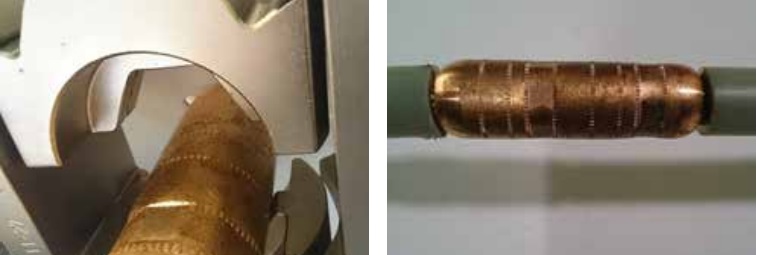
Figure 34 – Hexagonal compression die and copper connector (for stranded copper conductor) showing first compression position
Figure 35 shows a hexagonal compression lug with tool guide marks on the barrel.
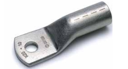
Figure 35 – Compression lug showing guide marks for hexagonal compression tool positions
For deep indent compression, as the name implies, an indenting tool is pressed deep into the connector body. Because of the amount of disruption caused by the crimping tool, the connector body must be fully supported in a cage which forms part of the tooling equipment (see Figures 36 and 37).
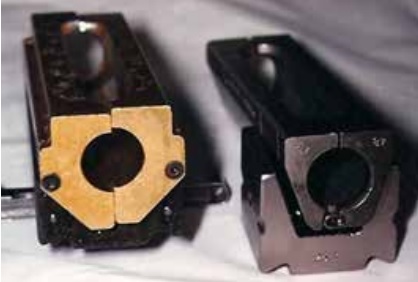
Figure 36 – Die cage for deep indent tool
A very important difference between these two compression technologies is the sequence of compressions. With hexagonal compression the first tool position is nearest to the connector centre, but with deep indent compression the first tool position is at the end of the connector, working towards the centre.
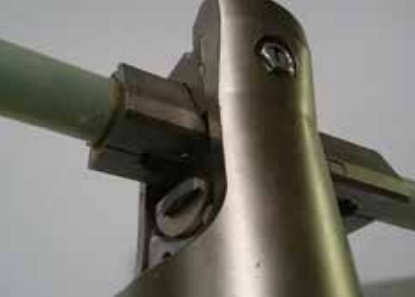
Figure 37 – Second deep indent position
After installation, compression connectors should be carefully checked for any sharp edges or points. It is essential that any sharp edges or points are removed using a file or abrasive cloth. The installation instruction may include this step. The connector body and nearby surfaces must then be thoroughly cleaned to remove any metal particles or other contaminants. Installation instructions may also require the depressions in the body of deep indent connectors to be filled with a mastic or putty (usually supplied in the kit).
Bolted connectors
Bolted (or ‘mechanical’) connectors have screws which are tightened to contact the conductor within the bore of the connector. These connectors are steadily gaining in popularity because they are size range-taking (which is convenient for inclusion in accessory kits) and usually require no special installation tooling. In addition, most of those for MV applications have shear-head screws where the screw head or part of the screw shank breaks away when the correct tightening torque is reached. This takes away requirement on the installer to apply a controlled torque. Sheared screws generally leave a relatively smooth profile over the cylindrical body of the connector. Any projecting points or edges must be removed using a file or abrasive cloth.
Bolted connectors may be installed using standard hand wrenches if the screws have hexagonal heads (see Figure 38) or hexagonal sockets (see Figure 39). The sequence of screw shearing is from the screw nearest the connector end, working towards the centre. It is good practice to tighten screws progressively from one to another until all are tight but not sheared. The first screw should then be further tightened until it shears.
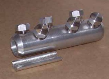
Figure 38 – Bolted connector with hexagonal head
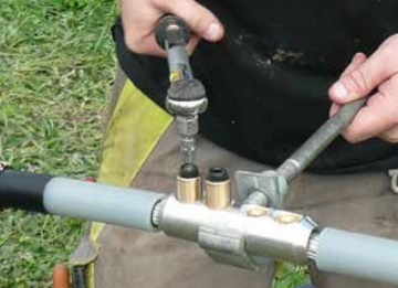
Figure 39 – Bolted connector with hexagonal socket
The use of a hand-operated wrench gives maximum control over the tightening and shearing procedure but some connector manufacturers allow the use of power impact wrenches to tighten and shear the screws. It is essential that the installation method is in accordance with the connector installation instruction or the manufacturer’s recommendation.
Range-taking of bolted connectors may extend to three or more standard conductor sizes. These connectors will probably be fitted with screws having several shear positions (Figure 40 left) or a ‘step-less’ shear feature making the screw shear flush with the connector surface (Figure 40 right). With most joints and terminations it is important that the sheared screw thread does not project above the cylindrical profile of the connector body after installation.
The installation instruction may require the use of a file or abrasive paper to remove any projections of the sheared screws. If this is the case, metallic filings or dust must be completely cleaned from the connector body and nearby surfaces.
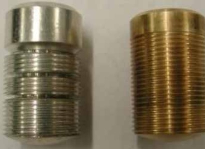
Figure 40 – Multi-shear position (left) and step-less shear (right) screws
Range-taking bolted connectors may include metal inserts (see Figure 38) or plastic centring rings (see Figure 41) intended to position smaller conductors concentric within the bore of the connector. Centralising inserts must be used (for smaller conductors) or discarded (for larger conductors) according to the installation instruction.
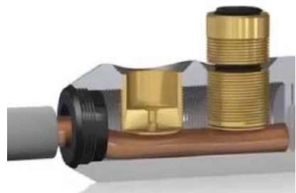
Figure 41 – Plastic insert (black) for centring a small conductor in the connector body
It is good practice to use a connector support tool to prevent twisting of the connector (see Figures 39 and 42). This is particularly necessary when working with small cable conductors to avoid bending of the conductor either side of the connector.
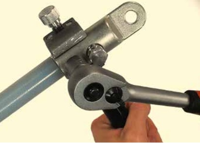
Figure 42 – Use of a support tool for installation of a shear-head mechanical lug
Further Reading
- Cables | MV Paper Insulated v MV Polymeric Insulated Cables
- The Installation Site | MV Cable Joints & Cable Terminations
- First Steps | MV Joints, Jointers & Initial Considerations
- Cable Preparation | Jointing & Terminating Aspects of MV Cable Preparation
- Earth Bonding | Joints & Terminations & Overheating Prevention
- MV Cable Accessory Technologies | Heat Shrink, Cold Shrink & Push-on
- MV Cables & Causes of MV Cable Failures
- MV Cables | Electric Field & Stress Control

LV, MV & HV Jointing, Earthing, Substation & Electrical Eqpt
Thorne & Derrick International are specialist distributors of LV, MV & HV Cable Installation, Jointing, Duct Sealing, Substation & Electrical Equipment – servicing UK and global businesses involved in cable installations, cable jointing, substation, overhead line and electrical construction at LV, 11kV, 33kV and EHV.
THORNE & DERRICK Product Categories: Duct Seals | Cable Cleats | Cable Glands | Electrical Safety | Arc Flash Protection | Cable Jointing Tools | Cable Pulling | Earthing | Feeder Pillars | Cable Joints LV | Joints & Terminations MV HV


