Cable Jointer: Darren Street Cable Jointer at D+R Jointing Services
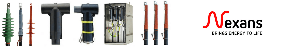
Featured Manufacturer: Raychem
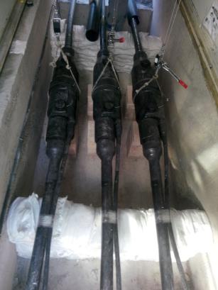
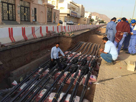
11kV Triplex Cable Joints
11kV triplex cables provide high voltage (HV) mains power distribution for utility and industrial applications – 11kV triplex cable consists of three single core high voltage cables in triplex formation according to BS7870 – 4.10. separable connectors are also known as screened elbow connectors or tee connectors.
11kV heat shrink cable joints suit unarmoured and armoured cables – this includes high voltage industrial power (XLPE BS6622 BS7835 with aluminium wire armour AWA) and marine offshore ship cable (EPR BS6883 with galvanised/phosphur wire braid) and copper wire or copper tape screen. Suitable also for BS7870 triplex cables.
Options include transition (PILC to XLPE) and transition trifurcating (3 x single core PILC to 3 Core XLPE) cable joints.
HV CABLE JOINTS – HEAT SHRINK JOINTS 11KV 33KV HIGH VOLTAGE CABLES
Heat shrink cable joints include straight, transition and branch types for XLPE, PILC and EPR single and 3 core cables – suitable for all types of polymeric and paper insulated medium/high voltage cables with/without steel wire armour or braid, copper tape/wire screens and copper or aluminium conductors up to 33kV.
Heat Shrink Cable Joints For 11kV High/Medium Voltage Cables
Cable Joints | 11kV 33kV | Medium & High Voltage Cables MV HV | Heat Shrink
Should you require any assistance with the selection or specification of 11kV triplex cables please do not hesitate to contact us.
T&D distribute the most extensive range of LV, MV & HV Cable Jointing, Terminating, Installation & Cable Pulling Equipment – we service UK and international clients working on underground cables, overhead lines, substations and electrical construction at LV, 11kV, 33kV and EHV transmission and distribution voltages.
This video by 3M Electrical shows how to splice a 15kV SHDC cable using 3M Mining Cable Splice Kit 3103 safely.
3M Mining Cable Splice Kit 3103 may be used for flexible conduit and mining jacket repairs, as well as for cable splicing and jointing mine and portable cable.
3M 3103 cable splices and joints are for use on 3-conductor mine and portable cables, type SHD-GC, MPF-GC and MPF; # 6 AWG-500 kcmil; 5kV, 8kV, 15kV.
3 rolls 3M Scotch 130C linerless rubber self-amalgamating tape – ¾” x 30 ft
Cable Preparation
Position cable end so that the colour rotation matches. Circle cut the cable jacket 12” from each end. Be sure not to damage the cable conductors. Measure 14” from the cable end and fully taper down to the circle cut.
Remove 12” of the cable jacket and cable fillers. Scuff and clean 4” of the cable jacket beyond the top of the taper. Hold back the grounds and ground check conductors and temporarily tape to cable with Temflex 1700P vinyl tape.
Select one conductor and cut at 9”. Match this conductor with the same colour conductor on the opposite end. Take the next conductor at 6”. Remove ¾” of the braid or tape metallic shielding from each conductor plus one half the connector length plus ¼”.
Remove cable semi con to ¼” of the shielding. Remove insulation for one half of the connector length plus ¼”. Pencil the insulation for ¾” and sand it smooth and even with electrical graded abrasive cloth.
Connecting Phase Conductors
Once the cable is prepared, join the power connectors with the proper connectors and cable crimping tool. Be sure the conductors butt up against the centre indents of the connector.
Note that ground wires and ground check will be joined later.
Applying Primary Insulation
Apply two highly stretched half lapped layers of Scotch 13 from the edge of one taper to the other, making sure to completely overlap the exposed semi conductive shield. Next apply highly stretched half lapped layers of Scotch 130C and up onto the tapers.
Build up half lapped layers building onto the existing insulation to 1/8” from the edge of the original cable semi con. The taper should be wrapped equal or greater than the original insulation.
Apply 2 highly stretched half lapped layers of Scotch 13 over the Scotch 130C overlapping the edges of metallic shielding.
Starting 2” up on the exposed metallic shielding wrap 1 half lapped layer of Scotch 24 over semi conductive tape continuing onto the opposite shielding for 2”.
Secure with a half inch square knot and trim the ends. Repeat connecting the phase conductors and applying primary insulation for the remaining phases.
Connecting Ground Connectors
Beforre cutting the ground wires reposition the spliced power conductors so that the conductors are returned to the natural helix of the cable. Lay the ground wires in their natural position in the valley between the two power conductors. Allow the ground to link staggered so as to avoid connection over the power conductor connections.
Join the conductors with the proper connectors and appropriate crimping tool. If present, connect the ground check conductor after trimming it to the proper length and remove one half connector length of the insulation from each lead.
On the ground check, clean the insulation 1” on both sides of the connection and apply one half lapped layer of 3M Temflex 1700P, one half lapped layer of Scotch 130C and one half lapped layer of 1700P over the connector and the clean insulation. Connect the remaining ground wires.
Jacketing The Splice
Bundle the cable assembly and bind it with 3M Temflex 1700P tape. Cover 1700P tape with one half lapped layer of Scotch 2228 and starting half way up the tapers, wrap half lapped layers of Scotch 130C building up and across the splice until the tape is equal to or greater than the original jacket thickness and extends 1” past the top of the jacket tapers.
Start 2” beyond the Scotch 130C tape and wrap one half lapped layer of Scotch 31 tape extending 2” beyond the 130C tape on the opposite end. Always wrap the Scotch 31 tape toward the machine end of the cable.
Start 1“ past the Scotch 31 and apply 3 half lapped layers of 3M Temflex 1700P to each end to temporarily secure the ends of the Scotch 31 tape jacket until the jacket reaches full bond.
Repairing Damaged Cable Jacket
Remove damaged cable jacket and taper the jacket approximately 2”. Scuff and clean 4” of the cable jacket beyond each split end. Bundle the cable assembly and bind with 3M Temflex 1700P tape.
Cover the Temflex 1700P tape with one half lapped layer of Scotch 2228. Wrap half lapped layers of Scotch 130C building up and across the splice until it is equal to or greater than then original jacket thickness and extends 1” beyond the top of the jacket tapers.
Start 2” beyond the Scotch 130C tape and wrap one half lapped layer of Scotch 31 tape extending 2” beyond the 130C tape on the opposite end. Always wrap the Scotch 31 tape toward the machine end of the cable.
Start 1“ past the Scotch 31 and apply 3 half lapped layers of 3M Temflex 1700P to each end to temporarily secure the ends of the Scotch 31 tape jacket until the jacket reaches full bond.
Cold Shrink – invented by 3M over 40 years ago and now the preferred technology for heat-free jointing, terminating, sealing and abandonment of LV HV cables
We hope you find this video informative and educational, contact T&D for technical support, quotations and stock availability for 3M Mining Cable Splice Kit 3103.
➡ Visit 3M Electrical for further information about joints, terminations, tapes and insulation to seal, repair, splice and connect LV MV HV cables.
T&D are Main Distributors & Stockists for the Pfisterer range of Medium Voltage Power Products including Connex Plugs, SEANEX Connectors, Cable Jointing Tools, Sicon Connectors, Surge Arresters and Electrical Safety Equipment.
Jointers blog
Subscribe now to our POWER NEWSLETTER– a monthly email circulation packed with news, projects, videos, technical tips, training information, promotions, webinars, career opportunities and white papers.
Includes access to our popular JOINTERS BLOGwith contributions from utility professionals, linesmen and cable jointers working on MV HV EHV cables and overhead lines typically at 11kV, 33kV, 66kV and up to 132kV.
15,000+ Subscribers. ➡
Images Courtesy of: Steven Onley – Submarine Cable Project Manager at 33Below Pty Ltd and Matthew Shields – Technical Director & Marine Engineer at Vocus Communications.
Steven Onley has 30 years of experience in submarine cable marine installation, covering all facets from contract bidding to system handover, including all offshore operations such as survey, shore ends, jointing, main lay, plough burial, PLIB and repairs as well as office-based project management. Services provided:
Desktop Studies
Route Surveys
Route & Cable Engineering
PLGR/RC
Cable Transfers
Shore End Landings (Direct & Pre-laid)
Main Lay & Burial
Post Lay Inspection & Burial (ROV)
Cable Repairs
Land Cable
Procedures & Reporting
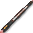
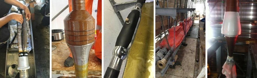
Pictured: Jointing & Connecting Submarine Cables
Steven explains ‘How do you connect submarine cable? It is not quite as simple as just making a fibre splice. Cables may only have 6-12 fibres in them, but a cablejointmay take a team of 4 cable jointers as long as 18 hours to complete.
As well as making a low loss splice (<0.1dB), we need to reinstate the mechanical strength of the cable(>8 tonnes min breaking load, depending on the cable type), and also the high voltage electrical insulation (up to 12kV DC). This takes some very specialised skills.
An added complication is that each supplier like ASN or SubCom has their own proprietary method of jointing their cable. It would be impractical for repair ships to be equipped with a complete set of every supplier’s equipment, so the suppliers created the Universal Joint Consortium. A UJ (Universal Joint) kit can connect almost any type of cable to any other type of cable, regardless of supplier. Thanks to Mathew Shields for some of these photos, showing an ASN (Alcatel Submarine Networks) cable joint’
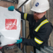
This is what can happens when there is a small scratch or contamination in the cable insulation. Submarine cables are usually powered with several thousand volts DC, which can cause a blow-out of the plastic insulation.
This example is only small (<10mm across – white cable is 21mm diameter) but it was quite spectacular when it arced as it ran along the deck while powered. You can see the burn marks around the edges as the plastic melted.
Heat Shrink Cable Accessories for 11kV Triplex Cables
Thorne & Derrick International are specialist distributors of LV, MV & HV Cable Accessories, Jointing, Substation & Electrical Equipment – servicing UK and global businesses involved in cable installations, jointing, substation, overhead line and electrical construction at LV, 11kV, 33kV, 66kV and EHV.
Nexans has achieved electrical Type Test of a 525kV DC Gas Insulated Switchgear (GIS) Sealing End according to CIGRE TB 496 with the cooperation of Siemens Energy
In the frame of the high voltage direct current (HVDC) market, the cables with an insulation composed of cross-linked polyethylene (XLPE) have emerged in the last ten years and allowed the deployment of innovative electrical grids in Europe and worldwide.
Nexans’ ecosystem encompasses best-in-class partners who share our values, working together to continually deepen our ability to stay a step ahead of what the market needs.
GIS type ends constitute an interesting component in the HVDC links due to the flexibility and compaction they allow in the connection of cables of different structures, especially in congested spaces such as an offshore platform. It is also suitable for use in back-to-back mode, thus constituting a mixed joint (e.g. between cables of different technologies).
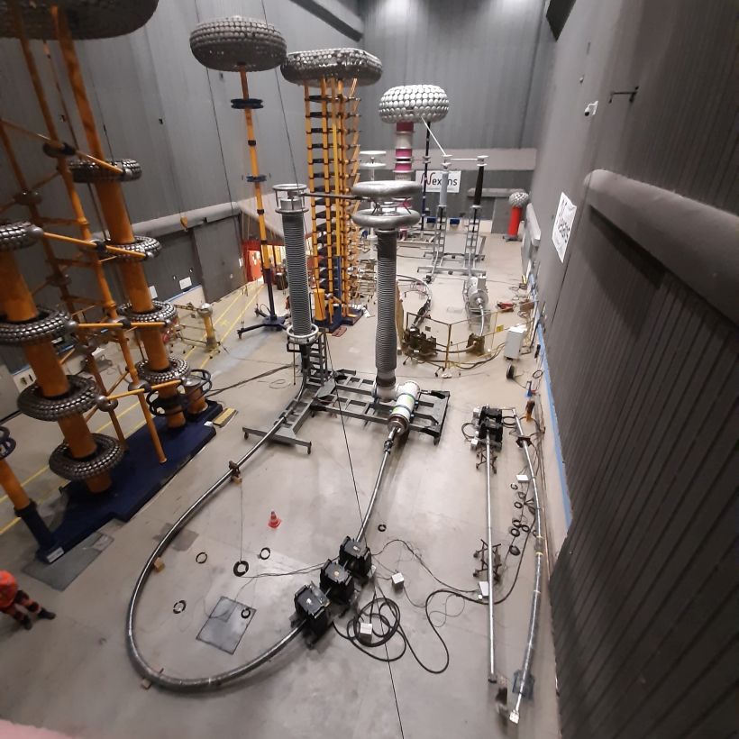
Nexans developed a dedicated GIS cable sealing end for a 525kV DC XLPE cable system. The studies on electrothermal aspects of the interface resulted in an optimized accessory design. The solution consists in a Nexans GIS termination plugged in a Siemens Energy DC GIS enclosure both compliant with IEC 62271-209 standards dimensions.
The validation of the solution has been successfully completed through an electrical 525kV DC VSC Type Test according to CIGRE TB 496. The test was accomplished in Nexans Calais high voltage laboratory under the certification of an independent third-party. This technologic breakthrough allows Nexans to offer competitive products for the deployment of HVDC links with direct connection to DC GIS.
Nexans developed a dedicated GIS cable sealing end for a 525kV DC XLPE cable system.
At Nexans, we are leading the charge to the new world of electrification: safer, sustainable, renewable, decarbonized and accessible to everyone – connecting us all to new opportunities, technologies and behaviours that will build a better future.
Thorne & Derrick
Nexans Main UK Stockist & Distributor
Contact us for Competitive Prices & Fast Delivery from Stocks for Heat Shrink, Cold Shrink & EPDM Rubber Connectors, Joints & Terminations up to 66kV.
Go to our Price List and contact us with your enquiries.
Heat Shrink Cable Accessories for 11kV Triplex Cables
Thorne & Derrick International are specialist distributors of LV, MV & HV Cable Accessories, Jointing, Substation & Electrical Equipment – servicing UK and global businesses involved in cable installations, jointing, substation, overhead line and electrical construction at LV, 11kV, 33kV, 66kV and EHV.
Compound Box Filling Compound end boxes rarely get attention — until one fails. Across ageing networks, replacement of compound-filled end boxes is becoming more frequent, particularly where original insulation systems have deteriorated and air insulation is not practical because...
Nexans 240–300mm² Multi-Joint – Medium Voltage Cable Joint Installation Medium voltage cable jointing requires reliability, consistency and safe installation practices. The Nexans 240–300mm² Multi-Joint is designed to simplify medium voltage jointing while maintaining high electrical performance for demanding power...


")