

Cable Transits
Modular Substation Cable Termination Design | Roxtec Whitepaper
May 11th, 2021
Abstract
The methods for cable penetrations into modular industrial substations are summarised using cable transits manufactured by Roxtec.
The requirements for structural and environmental integrity, grounding, sealing, fire protection and ease of expansion for a cable termination system are discussed. Current methods of installation are compared to using a cable transit design for installing and terminating cables in electrical substations.
Index Terms – cable termination, modular substation, cable transit.
Introduction
Modular substations are becoming the preferred approach for installing electrical and control equipment in industrial facilities.
The ability to prefabricate a building, pre-install both electrical and control equipment and the ability to pre-commission equipment prior to the installation helps to reduce on-site construction installation costs. This is particularly advantageous in remote project locations where the cost of labour can be very high.
The on-site termination of conductors and cables into equipment can often be an issue.
The equipment layout, the design of the modular building skid base frame, the number of terminations and the termination method can all influence the speed and ease of installation. Choosing the wrong penetration approach can compromise the environmental integrity of the building and equipment, significantly increase installation cost and complicate the ability to install cables and conductors in the future.
This has a direct impact on the cost of ownership over the life of the asset.
Modular Substation Fundamentals
A typical modular substation consists of a steel frame skid base supporting a prefabricated insulated panel constructed building.
The dimensions of the building can vary and is usually determined by the amount of equipment installed and the transportation logistics for a project.
It is common to see substation buildings with dimensions in excess of 30 meters in length, 7 meters wide and 6 meters high for domestic onshore projects. If the equipment layout dictates a larger building footprint, often the building will be split in two for transport to site.
Interconnecting wiring between equipment is usually done in one of two ways. If the substation is constructed on raised piles, and the wiring connections are internal to the substation, the conduits or cables are run overhead within the substation.
External field cable connections are then terminated into the floor of the substation directly into the equipment item. This approach has the advantage of minimising the height of the building and allowing for convenient access for workers to terminate field cables.
Fig. 1 illustrates this concept.
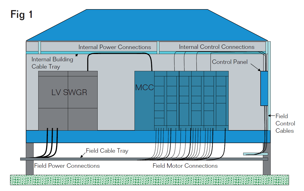
Modular Substation Cable Termination Design | Figure 1
Terminating Cables in substations
There are a number of challenges associated with terminating cables in a modular substation.
The first being the number of field terminations. In a medium sized industrial substation servicing a large number of motor interconnections, there may be up to 300 or more power and control cable terminations. The terminations must be coordinated with the location of the electrical and control equipment and the skid frame steel members supporting the building.
Often, a large number of cables must be terminated in a very limited area leading to cable and connector congestion which can impact worker productivity. Another challenge associated with terminating field cables is maintaining the environmental integrity of the equipment and the substation building envelope. This requires that the termination method maintain a vapour-tight weather barrier with a suitable insulation ‘R’ factor value to avoid condensation within the equipment and the building envelope.
The cable termination method should also provide a fire resistant barrier in the unlikely event of a fire. The cable termination method must accommodate a variety of cable construction configurations and wiring methods.
Cable diameters can vary with some control conductors with diameters of 5 mm or less to 3/C 500MCM armoured power cables which may have diameters of 100 mm or more. In each case, the cable must be properly secured and grounded in accordance with the local electrical installation codes and requirements. One often overlooked aspect of the cable termination method is the ability to add cables in the future.
The flexibility to easily add additional cable can pay dividends even during the initial installation when design modifications are made late in the installation phase of a project.
Traditional cable termination options
There are several cable termination methods currently used to terminate conductors into industrial substations. Some projects prefer that all cables are terminated into the top of electrical and control equipment mounted inside the building. A cable transit barrier is often used to allow cables to pass through an exterior wall.
Fig. 2 illustrates a method where cables are terminated into the floor of a substation. A ¼” steel removable panel is used to facilitate the pre-drilling of holes for the cable connectors prior to the field installation. This helps to improve construction productivity by allowing the majority of the cable connector entry holes to be drilled in a shop environment. Once the connector plate is fastened in place, drilling becomes more difficult and time consuming.
There is also the potential for metal filings to contaminate the switchgear cable termination compartment. Each connector hole must also be de-burred to prevent the conductor insulation from being damaged when the cable conductors are pulled into place. A second option for terminating cables is illustrated in Fig. 3.
A section of the floor is removed and the cable is terminated directly into the floor mounted equipment. Some equipment, such as low voltage motor control centres (MCCs) incorporate a removable plate to facilitate the punching of holes for cable connectors. The removable plate is usually constructed of sheet metal steel and is easily punched using a hydraulic punch.
The primary disadvantage to this termination method is that large sections of the floor must often be removed to gain access to the underside of the equipment. This may compromise the structural integrity of the floor and building envelope.
Future cable entry is also difficult as access to the plate must be provided both above and below the cable connector location. In certain cases, if the plate is not of sufficient thickness, large cables can deform the plate, further compromising the integrity of the installation.
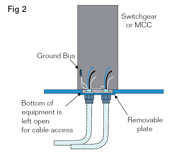
Cable Termination into Floor of Substation | Figure 2
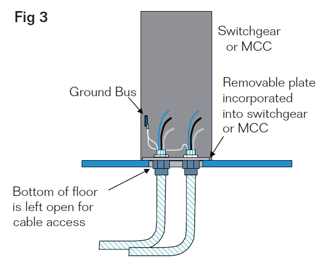
Cable Termination directly into Switchgear/MCC | Figure 3
Improved cable termination option
using a cable transit system
A third option for terminating cables into a substation is to use a transit entry frame. Fig. 4 illustrates a transit entry installation.
The transit frame is welded or bolted to the substation floor at strategic locations where cables will be terminated. The cables are then pulled into place through the transit frames and then sealed using Multidiameter™ cable transit blocks and a mechanical compression wedge.
The cable transit system provides cable retention and provides an environmental, fire resistant and gas tight seal to the equipment and building enclosure. There are several advantages to using a cable transit for cable entry in to a substation. The first being efficiency.
A cable transit allows multiple cables to be pulled at the same time though the transit opening. The large opening eliminates the potential damage to the conductor insulation during installation. Secondly, the transit frame maintains the structural and environmental seal integrity of the floor and allows for a high density and capital efficient installation of cables within a very small footprint. Also, future expansion capacity is provided for each transit via unused cable blocks which can be easily removed and reinstalled for future cable installation.
Another significant advantage of sealing cables with a cable transit system is the additional room below the building floor and equipment that is provided by the extension of the transit frame. This depth may be customised to a depth equal to the height of the structural steel, and has a standard depth of 60 mm.
This additional working space assists with the restrictive bend radius of larger armoured cables and allows for proper cable alignment with equipment configuration.
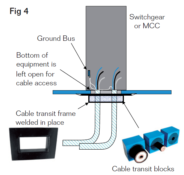
Cable Transit Installation for Switchgear/MCC Entry | Figure 4
Equipment Grounding for Tray Cables
There are two methods for terminating the bonding conductor of a tray cable using a cable transit system. The first involves connecting the bonding conductor directly to the ground bus of a switchgear or MCC. The PVC sheath is stripped back to the transit entry location and the bonding conductor is removed and connected to the equipment ground bus. The phase conductors then continue to the termination point in the switchgear or MCC. This is very similar to what occurs when a standard cable connector is used to terminate a conductor. Fig. 5 illustrates this method of bonding.
A second and less labor intensive option exists for grounding tray cables in MCCs. Some MCC manufacturers provide the option of a “unit” ground connection at the MCC bucket rather than on the equipment ground bus. This reduces the amount of cable sheath that must be stripped back in order to connect the bonding conductor to the equipment ground bus. This has the advantage of keeping the phase and bonding conductors together as an assembly within the equipment and breaking out the bonding conductor closer to where the phase conductor terminations actually occur. Fig. 6 illustrates this method of bonding.
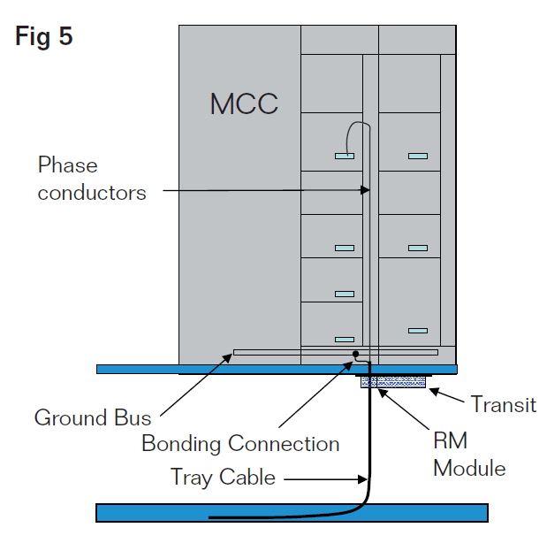
Option 1 for Grounding Tray Cable | Figure 5
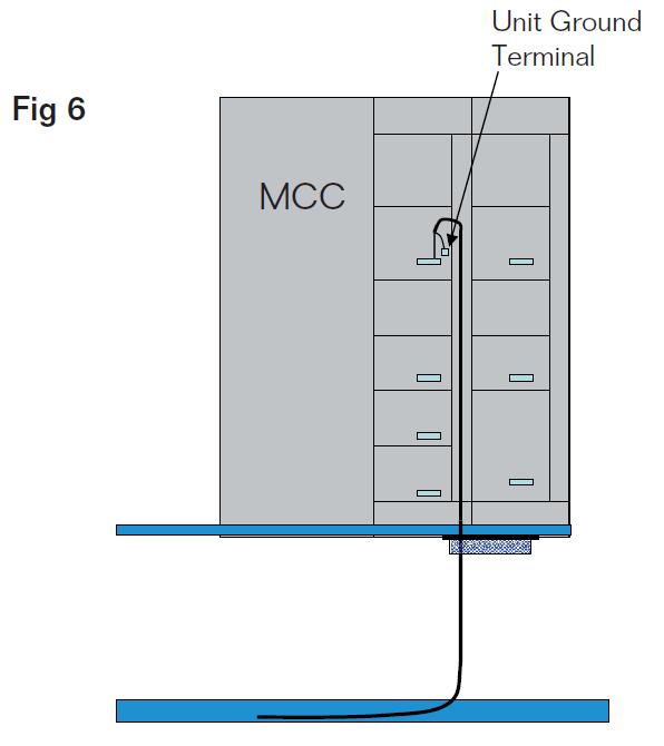
Option 2 for Grounding Tray Cable | Figure 6
Work process
To use a cable transit system to its fullest advantage, an understanding of the work process from design through final installation is required.
A. Engineering
The use of a cable transit for terminating cables into a substation requires pre-planning. The location of electrical and control equipment must be coordinated with the structural steel base to insure that transit frames of an adequate size and dimension can be installed without interference from support steel in the steel base. If possible, a standardised frame size helps to simplify the
design and installation process.
During the design phase, as cables are identified, they are assigned to a transit frame. This information can be integrated into the cable schedule or often dedicated software is used to create detailed transit schedules. Once the transit schedules are complete, the bill of material can be generated for both the substation fabricator and field installation contractor.
Fig. 7 illustrates a typical engineering drawing produced by Roxtec RTM Software for an MCC transit with capacity for 43 cables of various diameters installed within a 23 cm x 26 cm window. The flexibility of this system allows cable and pipe sizes ranging from 3 mm (.118 in) to 99 mm (3.898 in) to be sealed within the transit frames.
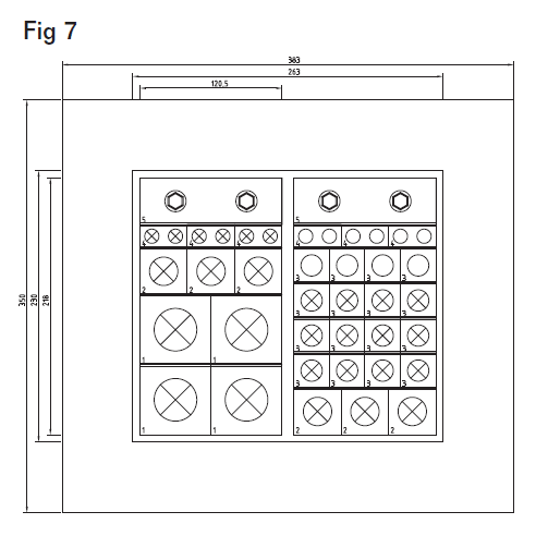
Engineering Drawing of Cable Transit System | Figure 7
B. Fabrication
Once the size of the cable transit and the locations are identified, the transit frames can be purchased and shipped to the fabricator for installation. The transit frames are mounted into the wall or floor by bolting or welding and then temporarily sealed for transportation to site.
C. Site Installation
After the modular substation is shipped to site and set in place, installation of the field conductors can begin. The site installation contractor will install interconnecting cables from source to destination via the cable transit openings identified on the cable schedule. The large opening provided by the cable transit helps the installer pull the cable into place and minimises any damage to the conductor insulation. When all cables for a cable transit are installed, the cables are secured and sealed using the cable transit blocks with stay plates and a mechanical compression wedge. The cable transit drawings help to identify what cables should be placed where and what size cable block should be used. The transit schedules also record how much spare capacity is available in each cable transit for future growth. Cables can be easily added without cutting or drilling additional holes, simply by loosening the compression wedge. Training is essential to help field installers understand the transit termination concept.
Training can be provided using on-site training services or by installation videos that provide step-by-step instructions. Once the installer has observed and installed the transit blocks for one transit installation, subsequent transit installations are easily completed. Figure 8 illustrates the installation of a transit barrier in a modular substation application.
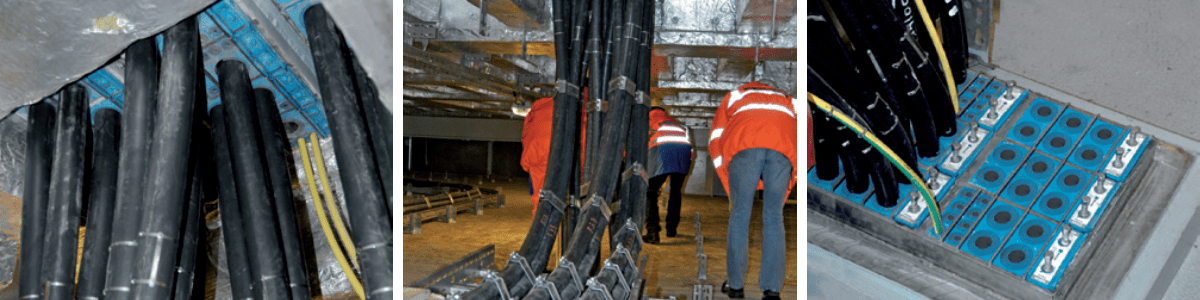
Figure 8
Conclusion
There are several advantages to using a cable transit for installing and terminating cables in industrial substations. It provides a standardized design with the flexibility to terminate a variety of different sizes and cable constructions. The ease of installation helps to reduce labor costs and minimize the potential for insulation damage. The structural and environmental integrity of the wall or floor penetration is maintained providing an insulated, vaportight and fire-stop barrier and cables can be easily added in the future. Cable transits are a viable alternative for terminating cables into industrial substations.
H. Vita
Allan Bozek, P.Eng., MBA graduated from the University of Waterloo in 1986 with BASc in Systems Design Engineering and a MBA from the University of Calgary in 1999. He is a Principal with EngWorks Inc., providing consulting engineering services to the oil and gas sectors.
Roxtec International AB, the parent of Roxtec, Inc. was established in 1990 and is the global leader in modular cable and pipe sealing systems. Roxtec maintains more than 250 registered tests and approvals and serves the oil & gas, telecom, marine, industrial and OEM industries in more than 70 markets around the globe.

LV MV HV Jointing, Earthing, Substation & Electrical Eqpt | Distributors for Roxtec Cable & Pipe Sealing Transit Systems
Roxtec Sealing Solutions For Cables & Pipes | Process Industry Whitepapers
November 13th, 2020
Roxtec are global-market leaders in the innovation and manufacture of cable transits and pipe penetration sealing systems to the process and hazardous area industries.
Roxtec solutions seal cables, cable ducts and pipes against water ingress, gas migration and fire hazards into safety critical and sensitive electrical equipment and buildings.
Whitepapers
- Whitepaper: EMP/EMI Protection In Control Rooms/Centres In Critical Infrastructure
- Whitepaper: Roxtec Multi-Cable Transit Devices
- Whitepaper: Modular Integration of Process Equipment Packages for Oil and Gas Facilities
- Whitepaper | Modular Cable Termination Design By Roxtec
 | Ex e and Ex tb Explosion Protection Certified by ATEX & IECEx | Zone 1/21 & Zone 2/22")
Hazardous Areas & Explosive Atmospheres (Gas & Dust) | Ex e and Ex tb Explosion Protection Certified by ATEX & IECEx | Zone 1/21 & Zone 2/22
Process Industry
Typical Applications
Buildings & E-houses
Wall entries
Floor entries
Underground entries
Control rooms
Analyzer shelters
Substations
Remote instrument buildings (RIB)
Field auxiliary rooms (FAR)
Local equipment rooms (LER)
Terminal Boxes, Cabinets & Enclosures
Remote I/O cabinets
Hazardous locations (Ex e)
Ordinary locations
Electric heat tracing systems
Automation and control cabinets
DCS panels
Motor control cabinets
Safety instrumented systems (SIS)
Fire and gas detection control cabinets
Machine monitoring systems
Lighting panels

Thorne & Derrick are distributors for Roxtec, the leading manufacturer of sealing solutions for cables and pipes, – protecting cables and pipes in the process industry sector against water, gas and fire.

CONTACT US WITH YOUR ENQUIRY
Specialist Distributors of Industrial & Hazarodus Area Equipment to provide Power, Heat, Light & Ventilation to the explosive atmospheres and process industries.
Control Panels | Plugs | Isolators | Enclosures & Junction Boxes | Lighting | Control Stations | Motor Starters | Heat Trace | Gas Detection | Flame Detection | Process Instrumentation | Process Heating | Ventilation Fans | Security Access Control

Competitive Prices | Extensive Stocks | Technical Support | Express Delivery
Roxtec Pipe & Cable Seals | Offshore & Onshore Windfarm Product Spotlight
November 3rd, 2020
Thorne & Derrick are Approved Distributors for Roxtec, the leading manufacturer of sealing solutions for cables and pipes, to protect electricity Transmission & Distribution assets including windfarm substations against water ingress, gas migration and fire hazards.
In this 2 part article series Roxtec provide an overview of sealing cables in LV MV HV applications for offshore and onshore substations and to help understand and learn about the importance of of sealing cable entry points and cable ducts.
Part 1

Part 2


Thorne & Derrick are Specialist Distributors to the UK and international Offshore Wind & Renewable industry to provide safe and reliable
LV HV Electrical Cable & Power Distribution Systems up to 66kV – we are highly customer responsive and absolutely committed to providing a world-class service.
Contact our UK Power Team for competitive quotations, fast delivery from stock and technical support or training on all LV-HV products.
Key Product Categories: Duct Seals | Cable Cleats | Cable Glands | Electrical Safety | Arc Flash Protection | Cable Jointing Tools | Cable Pulling | Earthing | Feeder Pillars | Cable Joints LV | Joints & Terminations MV HV

See how T&D support, supply and service the Renewable Energy industry.

MV HV Cables 11kV 33kV 66kV | Cable Joints, Terminations & Connections
Pipe & Cable Seals for Onshore Windfarm, Enclosures, Foundation & Stations
November 3rd, 2020Sealing Pipes & Cables
Roxtec Pipe & Cable Seals
Onshore Windfarm Substations, Enclosures & Foundation
Roxtec provides offshore wind farms with an “all in one” solution for cable entry sealing, cable management and vibration damping. Standardise with Roxtec seals for efficient offshore windfarm cable protection design, quick roll-out and certified protection – cables are securely fixed, sealed and cable lifetime is extended.
An overview of sealing cables in LV MV HV onshore windfarm, cabinets & enclosures, kiosks and foundation based upon industry standards and practical experience – see the Roxtec range of sealing products suited to the application below and the importance of sealing cable entry points and cable ducts.
Thorne & Derrick are distributors for Roxtec, the leading manufacturer of sealing solutions for cables and pipes, to protect electricity Transmission & Distribution assets including substations against the potential catastrophic effects water, gas and fire.
 Also: Sealing Cables In Onshore Substations – A Roxtec CPD

Sealing Cables In Onshore Substations
Pipe & Cable Sealing Application Areas
Roxtec have 5 application areas within the Onshore Wind Industry where there are great benefits from using their solutions:
- Cabinets & Enclosures
- Turbine Foundations
- Kiosks
- Collector Stations
- Landing Stations of Offshore Wind Farms
Cabinets & enclosures
Roxtec multi-cable entry seals are ideal for control cabinets, junction boxes and other electrical and instrumentation enclosures. By using our seals, you can handle high cable density and reduce the size and weight of the cabinets. Save time and labour with sealing solutions prepared for last minute changes.
Why use Roxtec?
- Watertight
- Firestop
- Gas-tight
- Cable Retention
Superior Simplicity
- One cut-out for dozens of pre-terminated cables
- Flexibility for cables and pipes of different sizes
- Built-in spare capacity for future cables and pipes
- EMC solutions for bonding, grounding and electrical safety
- Customized solutions for specific requirements

Turbine Foundations
Roxtec seals work efficiently in underground walls. Specify them with their knock-out sleeve to seal openings until cable routing. Avoid water, humidity and rodent issues in your turbine foundations.
Why use Roxtec?
- Watertight
- Pest and rodent barrier
- Cable retention
Superior Simplicity
- Flexibility for cables and pipes of different sizes
- Built-in spare capacity for future cables and pipes
- Installation in wet conditions and running water
Kiosks
Roxtec seals work efficiently in underground walls. Specify them with their knock-out sleeve to seal openings until cable routing. Avoid water, humidity and rodent issues in your kiosks. Roxtec seals take the load off the cables and eliminate the cable bending issue.
Why use Roxtec?
- Watertight
- Pest and rodent barrier
- Cable retention
Superior Simplicity
- Flexibility for cables and pipes of different sizes
- Built-in spare capacity for future cables and pipes
- Installation in wet conditions and running water
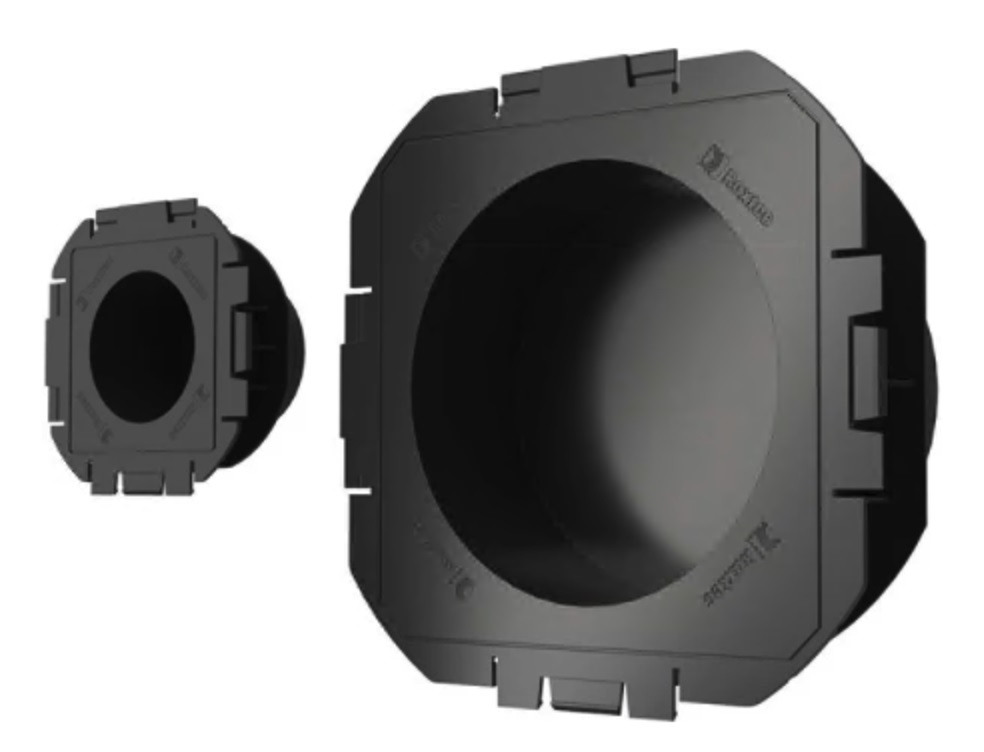
Roxtec Knock-Out Sleeve
Collector stations
Roxtec seals work efficiently in underground walls. Specify them with their knock-out sleeve to seal openings until cable routing. Avoid water, humidity and rodent issues in your collector stations. Roxtec seals take the load off the cables and eliminate the cable bending issue.
Why use Roxtec?
- Watertight
- Pest and rodent barrier
- Cable retention
Superior Simplicity
- Flexibility for cables and pipes of different sizes
- Built-in spare capacity for future cables and pipes
- Installation in wet conditions and running water
Landing stations of offshore wind farms
Roxtec seals work efficiently in underground walls. Specify them with their knock-out sleeve to seal openings until cable routing. Avoid water, humidity and rodent issues in your landing stations. Roxtec seals take the load off the cables and eliminate the cable bending issue. Fulfill EMC requirements with our EMC solutions for bonding, grounding and electromagnetic shielding.
Why use Roxtec?
- Watertight
- Firestop
- Gas-tight
- Dust-tight
- Pest and rodent barrier
- Cable retention
- EMI/EMP protection
Superior Simplicity
- Flexibility for cables and pipes of different sizes
- Built-in spare capacity for future cables and pipes
- EMC solutions for bonding, grounding and electrical safety
- Customized solutions for specific requirements
- Installation in wet conditions and running water
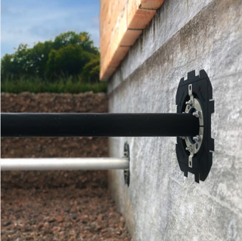
Seals for underground use – Use Roxtec UG™ solutions where cables and pipes enter basements in order to eliminate the risk of rodents, flooding and partial discharge.
Further Reading
- 132kV 33kV 11kV DNO Substations – A Guide To Cable Sealing By Roxtec
- Roxtec H3 Cable Transit Seals – How To Seal Substation Cables
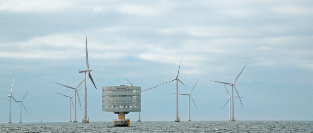
Roxtec | Lillgrund in Sweden is one of the largest offshore wind farms in the world generating green energy to 60,000 households with cables sealed and protected by Roxtec

Cable Transits – Sealing Cables & Pipes
Thorne & Derrick are Specialist Distributors to the UK and international Offshore Wind & Renewable industry to provide safe and reliable LV HV Electrical Cable & Power Distribution Systems up to 66kV – we are highly customer responsive and absolutely committed to providing a world-class service.
Contact our UK Power Team for competitive quotations, fast delivery from stock and technical support or training on all LV-HV products.
Key Product Categories: Duct Seals | Cable Cleats | Cable Glands | Electrical Safety | Arc Flash Protection | Cable Jointing Tools | Cable Pulling | Earthing | Feeder Pillars | Cable Joints LV | Joints & Terminations MV HV
See how T&D support, supply and service the Renewable Energy industry.
MV HV Cables 11kV 33kV 66kV | Cable Joints, Terminations & Connections
MV HV Cables 11kV 33kV 66kV | Cable Joints, Terminations & Connections
Whitepaper | EMP/EMI Protection In Control Rooms/Centres In Critical Infrastructure
October 19th, 2020
Abstract
This Whitepaper is written to visualise and implement means to protect electronic equipment in critical infrastructure against Electro Magnetic Pulse & Electro Magnetic Interference (EMP/EMI).
The paper by Roxtec, the world-leaders in the manufacture of cable transits initially describes potential EMP/EMI threats; both man-made and natural.
The main threats; natural EMP (like solar storms and lightning) and man-made EMP (like HEMP, NEMP, RFW etc) are presented and discussed as needed background information for planning of adequate protection solutions.
Introduction
- Definitions, Threats & Implications
- Terminating Cables In Substations
- Critical Infrastructure
- Authority Protection Requirements & Specs
- EMP/EMI Shielding Construction & Solutions
- Verification, Tests & Measurements
- Construction, Knowledge & Competence
- Documentation
- Reference Documents
Hazardous Areas & Explosive Atmospheres (Gas & Dust) | Ex e and Ex tb Explosion Protection Certified by ATEX & IECEx | Zone 1/21 & Zone 2/22
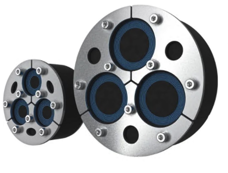
Roxtec modular cable transit seals are based upon a rubber design with seals that are constructed of a number of removable layers to secure a watertight, gas tight and fire proof seal around the cable or pipe – the range includes rectangular transits and round transits to fit a variety of pipes and cable sizes.

Process Industry
Typical Applications
Buildings & E-houses
Wall entries
Floor entries
Underground entries
Control rooms
Analyzer shelters
Substations
Remote instrument buildings (RIB)
Field auxiliary rooms (FAR)
Local equipment rooms (LER)
Terminal Boxes, Cabinets & Enclosures
Remote I/O cabinets
Hazardous locations (Ex e)
Ordinary locations
Electric heat tracing systems
Automation and control cabinets
DCS panels
Motor control cabinets
Safety instrumented systems (SIS)
Fire and gas detection control cabinets
Machine monitoring systems
Lighting panels
Thorne & Derrick are distributors for Roxtec, the leading manufacturer of sealing solutions for cables and pipes, – protecting cables and pipes in the process industry sector against water, gas and fire.
Further Reading
Sealing Pipes & Cables in the Hazardous Area & Process Industries Using Roxtec
- Whitepaper: Roxtec Multi-Cable Transit Devices
- Whitepaper: Modular Integration of Process Equipment Packages for Oil and Gas Facilities
- Whitepaper | Modular Cable Termination Design By Roxtec
CONTACT US WITH YOUR ENQUIRY
Specialist Distributors of Industrial & Hazardous Area Equipment to provide Power, Heat, Light & Ventilation to the explosive atmospheres and process industries.
Control Panels | Plugs | Isolators | Enclosures & Junction Boxes | Lighting | Control Stations | Motor Starters | Heat Trace | Gas Detection | Flame Detection | Process Instrumentation | Process Heating | Ventilation Fans | Security Access Control
Competitive Prices | Extensive Stocks | Technical Support | Express Delivery
