

MV Cable Accessory Technologies | Heat Shrink, Cold Shrink & Push-on
Published 10 Jan 2020

Installers should always receive Jointer training in the MV cable accessory technologies that they will work with.
Each technology has its own peculiarities and practice will be needed for the installer to become familiar with the individual skills needed. Installation instructions always have detailed information on cable stripping dimensions etc but not necessarily much guidance on techniques relevant to whether the accessory components are heat-shrink, cold shrink, push-on or maybe more than one technology.
The sections below highlight some important considerations for each of the major technologies used for joints, terminations and connectors at medium voltage (MV).
Heat-shrink accessories
Heat-shrinkable sleeves and moulded parts are made of special cross linked plastic materials that are heated and stretched (‘expanded’) and then cooled whilst held expanded. The expanded state becomes ‘frozen’ into the molecular structure. Extruded tubings and moulded parts are supplied in this state.
The installation process involves positioning and re-heating the expanded parts, usually with a propane or butane gas torch, until the parts shrink (‘recover’) on to whatever they have been placed (Figure 43). Because a naked flame is involved (or perhaps a powerful hot air gun), an appropriate level of installer skill is required to ensure full recovery using heat shrink torches, avoiding faults such as voids in the interfaces of insulating layers, or burning of the material surface.
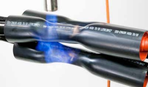
Figure 43 – Shrinking joint insulation screening tubings
Some important rules for successful installation of heat-shrink components are as follows.
- Use a gas torch designed for this purpose (not a torch designed for soldering).
- Adjust the torch to give a large soft yellow flame.
- Position part accurately as adjustment may not be possible after shrinking starts.
- Keep the flame moving around the shrinking component.
- Point the flame in the direction of shrinking.
- Do not move the accessory until the heat-shrink components have cooled.
Cold-shrink sleeves and moulded parts are also supplied in an expanded form but in this case on some form of rigid former or ‘hold-out’. The hold-out is removed during installation to allow the stretched part to recover into position on the joint or termination (see Figure 44). Cold-shrink components are usually made from soft flexible materials such as silicone rubber and EPDM.
Some important rules for successful installation of cold-shrink components are as follows.
- Check that the parts are within their ‘use by’ date.
- Keep the expanded components away from sharp objects.
- Use only the specified grease or other lubricant.
- Position the component accurately because adjustment may not be possible after recovery starts.
- Support the component in position and remove the holdout carefully and slowly without stretching the component.
- When removing spiral holdouts, the instruction may require the tape pulling position to be rotated around the cable to avoid snagging or tangling.
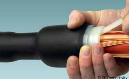
Figure 44 – Installation of a cold-shrink joint sleeve with spiral tape holdout
Push-on accessories
This is a general term referring to joints, terminations and separable connectors that are not supplied in an expanded form. Each part is sized such that it forms an interference fit with the cable and can be pushed into position, usually without the need for special tooling. These accessories are also referred to as ‘slip-on’.
There are many designs of terminations and joints in this technology category. Applications extend well beyond MV up to the highest system voltages. The most well known MV push-on accessories are fully screened separable connectors for connecting cables to electrical equipment via standardised bushings (see Figure 45).
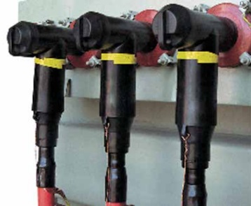
Figure 45 – Screened separable ‘T’ connectors (or ‘elbows’)
Some important rules for successful installation of push-on components are as follows.
- Check that the part is correctly sized for the cable diameter (because range-taking may be restricted).
- Apply only the lubricant supplied with the kit or recommended by the manufacturer.
- Install each component on to the cable in a single movement (do not stop part-way) into its final position.
‘Hybrid’ accessories
Some accessories comprise a mix of heat-shrink, cold-shrink and push-on components.
The recommendations applying to each technology should be followed. Some utilities favour joints that include a pourable resin. The usual function of the resin is to provide additional mechanical protection and/or moisture sealing. It is very important to follow closely the instructions for mixing and pouring of resin, including health and safety guidance for personal protection.
Further Reading
- Cables | MV Paper Insulated v MV Polymeric Insulated Cables
- The Installation Site | MV Cable Joints & Cable Terminations
- First Steps | MV Joints, Jointers & Initial Considerations
- Cable Preparation | Jointing & Terminating Aspects of MV Cable Preparation
- Conductor Connectors | Crimp v Mechanical Connectors with Joints & Terminations
- Earth Bonding | Joints & Terminations & Overheating Prevention
- MV Cables & Causes of MV Cable Failures
- MV Cables | Electric Field & Stress Control

LV, MV & HV Jointing, Earthing, Substation & Electrical Eqpt
Thorne & Derrick International are specialist distributors of LV, MV & HV Cable Installation, Jointing, Duct Sealing, Substation & Electrical Equipment – servicing UK and global businesses involved in cable installations, cable jointing, substation, overhead line and electrical construction at LV, 11kV, 33kV and EHV.
THORNE & DERRICK Product Categories: Duct Seals | Cable Cleats | Cable Glands | Electrical Safety | Arc Flash Protection | Cable Jointing Tools | Cable Pulling | Earthing | Feeder Pillars | Cable Joints LV | Joints & Terminations MV HV


