Ellis Patents Trident Trefoil Cable Cleats (24-83mm)
")
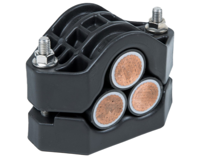
Trident Cable Cleats
Trefoil Cleats
- Maximum Short Circuit Test Level 94kA or 134kA
- Cable OD Ø36mm
- Cable Cleat Spacing – 600mm or 300nn
- Cable Cleat Type –Trefoil Cables
- Material – LSF
- Cleat Range Trefoil Cables – 24-83mm
Thorne & Derrick International, based in the UK, stock and distribute the complete range of cable cleats and cable hangers manufactured by Ellis Patents including the Trident range for short circuit retention and cable protection of LV (Low Voltage), MV (Medium Voltage) and HV (High Voltage) power cable systems in a trefoil installation.
The Ellis Trident® Polymer Cable Cleat are expertly engineered for securing cables in trefoil formation. Designed, tested, and manufactured in compliance with IEC 61914, this robust cable cleat ensures reliable performance in electrical installations, even under short-circuit conditions.
The cleat is available in a range of sizes with range taking ability to suit cables in trefoil formation. The cleat is manufactured as standard in LSF which is PFAS and halogen free, flame retardant and suitable for outdoor applications. For higher temperature applications GFN has the same material properties as LSF but offers a higher operating temperature. (+120˚C)
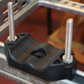
The Trident can be fixed to the supporting structure by either two M10 fixings or one M12 fixing. Fixings for the cleat can also be supplied.
Trident Cable Cleats
Key Features
- IEC 61914 Certified – tested and compliant with the latest international cleat standards
- Trefoil Cable Retention – ideal for high-performance LV, MV & HV cable installations
- PFAS & Halogen-Free – low smoke and fume material for improved safety
- Flame Retardant – safe for indoor and outdoor environments
- High Temp Version (GFN) – suitable for installations up to +120°C
- Mounting Options – install with two M10 or one M12 fixing
- Range-Taking Design – accommodates a wide range of cable diameters
- Fixings Available – fasteners supplied upon request
Ellis Trident Polymer Cable Cleat – Trefoil Formation
Compliant with IEC 61914 and available in both LSF (standard) and GFN (high‑temperature, up to +120 °C) options. Fixable with two M10 or one M12 bolt; fixings available on request.
| GFN Part No. | LSF Part No. | Cable Ø Range (mm) | W (mm) | H (mm) | D (mm) | P (mm) | Fixing | Weight (g) [GFN/LSF] |
|---|---|---|---|---|---|---|---|---|
| TR24-29GFN | TR24-29LSF | 24–29 | 122 | 91 | 77 | 92.5 | M10 | 360 / 288 |
| TR27-32GFN | TR27-32LSF | 27–32 | 126 | 95 | 77 | 98.5 | M10 | 370 / 296 |
| TR30-36GFN | TR30-36LSF | 30–36 | 134 | 104 | 77 | 104.5 | M10 | 383 / 306 |
| TR34-41GFN | TR34-41LSF | 34–41 | 144 | 112 | 77 | 114.5 | M10 | 485 / 388 |
| TR39-47GFN | TR39-47LSF | 39–47 | 156 | 124 | 77 | 125 | M12 | 568 / 454 |
| TR45-54GFN | TR45-54LSF | 45–54 | 172 | 138 | 77 | 145 | M12 | 666 / 533 |
| TR52-62GFN | TR52-62LSF | 52–62 | 190 | 153 | 77 | 160.5 | M12 | 793 / 634 |
| TR60-72GFN | TR60-72LSF | 60–72 | 215 | 177 | 98 | 182 | M12 | 1100 / 880 |
| TR69-83GFN | TR69-83LSF | 69–83 | 238 | 198 | 98 | 205 | M12 | 1300 / 1040 |

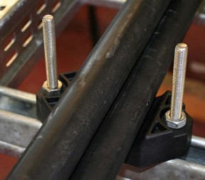
Installing Cable Cleats
Installation instructions for trefoil cables using Trident cleats manufactured by Ellis Patents:
1) If the cleat is being fixed with 1 x M12 fixings, see 1a, if it is being fixed with 2 x M10/M12 see 1b.
 |
 |
 |
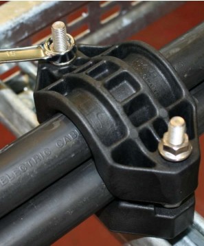 |
| 1a) Feed the closure fixings through the base of the cleat into the hex recesses. Place then the cleat on the mounting structure and fix the cleat from below using 1x M12 fixings through the central hole. | 1b) Place the base of the cleat on mounting surface and feed the 2 x M10 or M12 fixings through the base of the cleat (product size dependent) and the mounting structure. To hold the base down before the top is installed, the base needs to be fixed with two 2 x M10/M12 nuts (product size dependent) in the recesses provided (as detailed on the picture on the above). |
3) Lay the cable on the base on the cleat. | 4) Place top of the cleat on the base. Tighten the closure nuts to a maximum torque of 10N.m. Ensure that the nuts are tightened equally to ensure that the top is installed straight Note: Do not over tighten the cleat. The cleat should secure the cable but doesn’t need to be over tightened that the cable bulges on each side of the cleat. |
Torque
Nuts need to be tightened in a maximum torque of 10Nm. This is based on the strength of the clamp rather than the cable installed within. See the item 4 of Ellis’ guidelines on clamped cables.
Short-Circuit Performance & Testing (IEC 61914:2021)
-
Tested in GFN or LSF to IEC 61914:2021 certification standards.
-
Short-circuit ratings:
-
134 kA for 300 mm spacing on Ø36 mm cable
-
94 kA for 600 mm spacing on Ø36 mm cable
-
-
Temperature range:
-
GFN: –40 °C to +120 °C
-
LSF: –60 °C to +60 °C
-
Ellis Patents Trident Cable Cleats Testing Summary
Trident Cleats have been tested in line with the International Standard ‘Cable Cleats for Electrical Installations’ IEC 61914:2021. Typical results are detailed below, please note that these testing values are maximums and safety factors appropriate to your application should be used:
| Property | IEC 61914 Clause | Units / Classification | GFN Test Data | LSF Test Data |
|---|---|---|---|---|
| Cleat Type | 6.1.2 | Non-metallic | – | – |
| Temperature for Permanent Application | 6.2 | °C | –40 to +120 | –60 to +60 |
| UV Resistance | 6.5.1.2 | Xenon Arc (Method A) | Pass | Pass |
| Corrosion Resistance | 6.5.2 | N/A | N/A | N/A |
| Impact Rating | 6.3.5 | Heavy / Very Heavy | Very Heavy / Heavy | Heavy |
| Flame Propagation | 10.0, 10.1 | Application time ≥30s | Pass | Pass |
| Axial Load Rating | 6.4.3, 9.4 | Newtons (N) | 1100 | 1500 |
| Lateral Load Rating (Horizontal) | 6.4.2, 9.3 | Newtons (N) | 2250 | 2250 |
| Lateral Load Rating (Vertical) | 6.4.2, 9.3 | Newtons (N) | 2250 | 2250 |
| Short Circuit Withstand (300 mm Spacing) | 6.4, 6.4.5, 9.5 | kA | 134 kA (Cable Ø36 mm) – Report PDL-18.071.6 | 121 kA (Cable Ø36 mm) – Report PDL-22.159.2 |
| Short Circuit Withstand (600 mm Spacing) | 6.4, 6.4.5, 9.5 | kA | 94 kA (Cable Ø36 mm) – Report PDL-18.071.5 | N/A |
Cable Cleats v Cable Ties
The Video produced by Ellis Patents provides compelling evidence of the need to ensure all cables are adequately supported and retained to cable containment to protect against the devastating effects of short circuit faults: 118kA Short Circuit Fault Current | 0.1 Seconds Duration | 480V Low Voltage Cables.

Cable Lugs | Cable Glands | Feeder Pillars | Cable Joints LV | Joints & Terminations MV HV 11kV 33kV