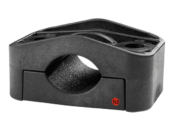
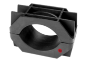
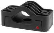
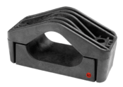
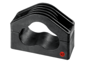
id-Technik KT Series Cable Clamps
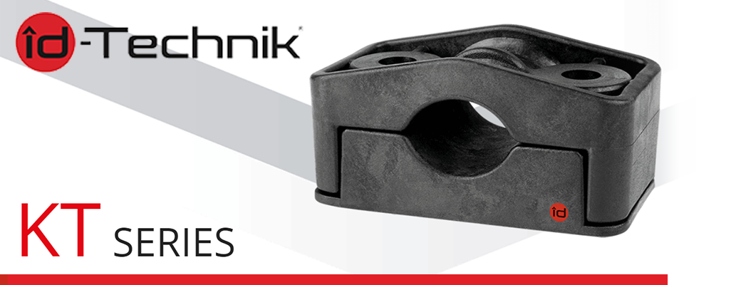
KT Series Cable Clamps | id Technik
CABLE CLAMPS | KT SERIES
id-Technik KT Series Cable Clamps are suitable for use with all types of single and multi-conductor HV, MV and LV power cables in indoor and outdoor applications – typically used to clamp and support MV HV power cables in the offshore wind industry including wind turbine generators, masts and shafts applications.
The cable clamps are designed to withstand the toughest environments and are resistant to UV radiation and exposure to chemicals.
The excellent material in id-Technik Clamps is non-toxic, not harmful to health, fully recyclable, self-extinguishing and low-smoke and zero halogen (LSZH). It is compliant with directive 2015/863/EU (RoHS) and regulation (EC) no. 1907/2006 (REACH regulation). The material is also non-metallic, non-magnetic and corrosion-resistant – it does not interact with the cable’s electromagnetic field.
Unlike metal cable cleats or clamps, no additional polymer coating is needed to protect the cable against mechanical damage, and KT series clamps do not need to be earthed.
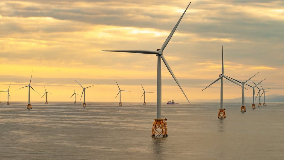
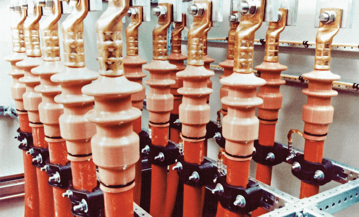
Cable Clamps & Cleats | id Technik cable clamps are specified extensively to provide cable support to both onshore, offshore and subsea wind farm power cables in both single or trefoil arrangement – this includes 11kV / 33kV substation, inter-array and associated medium or high voltage cables.

Complete range of industrial cable cleats including Hook | Claw | Plastic | Aluminium | Trefoil | Quad | LSF | Fire Resistant
➡ Read our Blog | IEC 61914 – Cable Cleats & Short Circuit Protection Calculations
id-Technik Cable Clamps are type-tested by accredited test institutes for the highest classification to the international standard IEC 61914.
id Technik KT Series Cable clamps – Technical Specification
Resistance |
Ultraviolet rays, ozone, mineral oils, fuels, salts, alkalis, alcohol, hydrocarbons, ketones, ether, termites and radioactive rays |
|
|
|
Flame resistance |
UL94 5VA (IEC 60695-11-20) UL94 V-0 (IEC 60695-11-10) IEC 61914 following IEC 60695-11-5 Classification following DIN 5510, part 2 Flammability class: S3 |
|
|
|
Thermal expansion |
0.01% per 10°C temperature increase |
|
|
|
Tensile strength |
120 N/mm2 |
|
|
|
Flexural strength |
210 N/mm2 |
|
|
|
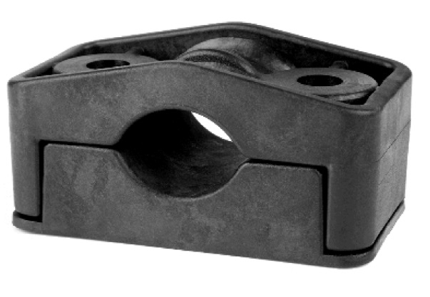
KT Series Cable Clamp
KT Series Cable Clamps Temperature Range
Ambient temperature |
down to -60°C* |
|
|
|
Continuous operation |
up to 120°C |
|
|
|
Permitted short-term heating |
up to 220°C |
|
|
|
Operation life |
more than 40 years of maintenance- and failure-free operation |
|
|
|
Technik Cable Clamps KT Series Dimensions
The below table shows the dimensions in mm for KT Series Cable Clamps.
| Type | DØ | DØ+ | DØ++ | L | B | I | H1 | H2 | h | a | dØ | Screw thread |
|---|---|---|---|---|---|---|---|---|---|---|---|---|
| KT 25/39 | 25-39 | 22-36 | 19-33 | 107 | 60 | 65 | 46-60 | 55-69 | 27 | 15 | 13 | M12 |
DØ++: ~ with two Elastic Inlays
- Tightening torque for fixing material – Top part: 5 Nm**, Bottom part: 15 Nm
- Dynamic Resistance to short circuits – 13.000 N
- Applications – For trefoil formation and stacked fastening of single-and multi-core cables. Universal application indoors and outdoors between -60°C and +120°C.
- Outer diameter of cables – 22 mm to 46 mm
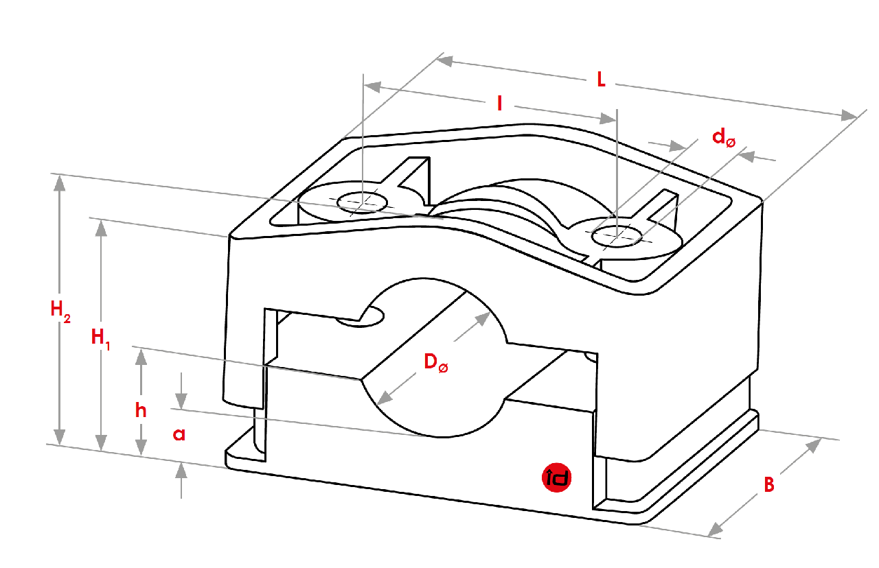
kT series dimensions
Features of KT Series Clamps
- High mechanical strength and heat resistance due to special fibreglass-reinforced polyamide.
- Type-tested to IEC 61914
- Very low surface pressure on cables due to Cable Clamps’ large contact area
- Unrestricted application both indoor and outdoor in extreme climates such as deserts, tropics, high altitudes, arctic climate, coastal salt fogs, flooding and ozone due to special resistance to ageing, ultraviolet rays and ozone
- Easy to mount without special instruments and maintenance-free
- Fastening of Cable Clamps adaptable to all local conditions
IEC 61914 Type-Tests – KT Series Clamps
| Classification
|
Test Conditions
|
Approved Results
|
| Material: non-metallic | high-grade polyamide | |
| Operating temperature | -60°C / +120°C | passed |
| Resistance to impact | -60°C, 5 kg at 400 mm height | very heavy |
| Lateral load test (N) – in x-direction – in y-direction |
At +120°C | 20.000 N 30.000 N |
| Axial load test (N) – without Elastic Inlays – with Elastic Inlays |
+120°C | 600 N 800 N |
| Resistance to electrodynamic forces [N] suited to withstand multiple short circuits |
Peak short circuit current: 151 kA Cable Clamp spacing: 0,84 m |
25.000 N |
| UV-resistance | high | passed |
| Flame propagation |
1 x 30s, needle flame method | passed |
| 2 x 10s, 50 W test flame method | V-0 | |
| 5 x 5s, 500 W test flame method | 5VA | |
| 3 min | S3 |
Assembly Instructions For KT Series Clamps
Selection of fastening material
Material and corrosion resistance
The choice of material for the fasteners is dependent on the installation environment and operating conditions (e.g. galvanised, stainless steel, etc.), strength grade 4.8 – 8.8
Fastener diameter
depends on the Cable Clamp (dimension: metric screw thread [M])
Type of screw
depends on the substructure (e.g. hexagon screws, T-head screws, rod threaded, etc.); not included in delivery
Fastener Length
depends on the Cable Clamp dimension and type of substructure
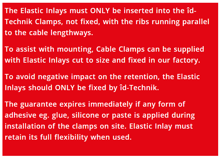
Application with Elastic Inlays
on-site fixing with any form of adhesive (e.g. glue, silicone or paste) will void the warranty immediately
KT Series Individual Components
| Cable Clamp type | Outer diameter of cable | Metric screw thread (M) | Recommended length of thread* |
|---|---|---|---|
| KT 25/39 | 25-39 mm | M12 | 83 mm + x |
* For maximum permitted outer cable diameter (can be reduced accordingly for smaller diameters)
x corresponds to the height of the substructure
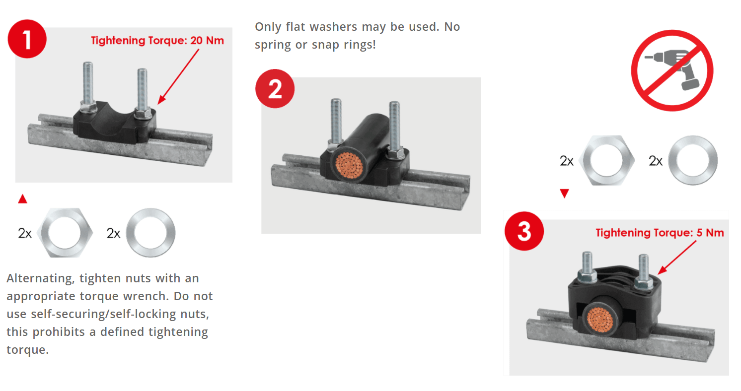
It is essential to respect the specified tightening torques, especially for the upper part, to guarantee perfect and reliable functioning of the cable installation for the long-term.**
Mounting
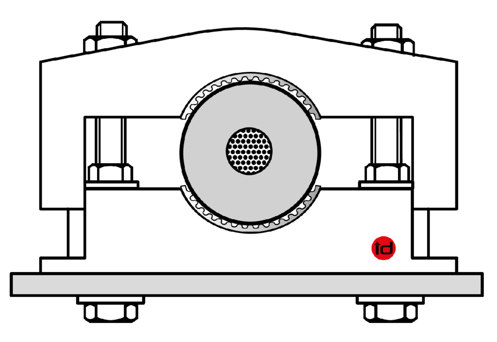
Each KT Series Clamp has a simple design, consisting of two sections. These components are secured together by fasteners; which also provide the attachment to the structure.
Thanks to the versatile range of attachment options, Clamp installation methods can be easily adapted to suit local circumstances – and the lower section can be pre-installed for ease of installation. There are no special tools needed to install id-Technik cable clamps.
Suitable separation between Cable Clamps depends on:
- Peak short circuit current
- Dynamic short circuit resistance of the Cable Clamp
- Cable design, including bending stiffness (bending modulus)
Use of Elastic Inlays
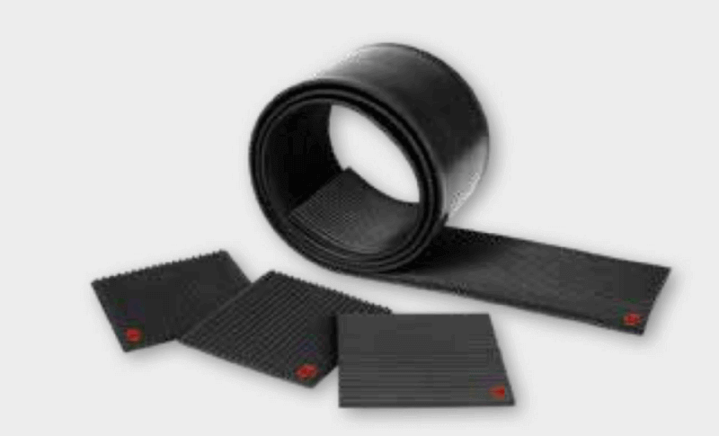
- Elastic Inlays can be used as a cushion for elastic adjustment of cable diameter changes due to operational load changes and/or changes in the ambient temperature
- Precise cable fixation and absorption of weight forces, primarily on cables installed along inclines or attached to vertical surfaces where restraint of axial movement is essential
- Compensation of vibrations, e.g. in wind turbines, without reducing retention forces
- Expansion of the Clamp’s clamping area, for cables with a smaller outer diameter
|
|
 |
|
Use with two Elastic Inlays, e.g. KT 25/39-2
|
 |
id-Technik was the first manufacturer to introduce a polyamide cable clamp to the world market offering an alternative to metal (aluminium or stainless steel) and wooden cable clamps. id-Technik distributes cable clamps for power cables of all voltage ranges (LV MV HV 1kV to 765kV).

Cable Lugs | Cable Glands | Feeder Pillars | Cable Joints LV | Joints & Terminations MV HV 11kV 33kV


