The following Whitepaper by G&W Electric and presented by T&D discusses the challenges that are encountered with aging electrical infrastructure with emphasis on insights into the planning, design, and execution of a major campus upgrade project at the California State University in Fresno, California.
The project had the objective to replace an aging electrical distribution system with one that delivers a continuous supply of power to all of the campus facilities, regardless of the reliability of the utility feed to the campus.
Thorne & Derrick are Specialist Distributors of Substation, Electrical Safety, Cable Jointing & Accessories to UK and international utilities and contractors providing electrical power at distribution and transmission voltage levels.
Introduction
This paper will provide insights into the planning, design, and execution of a major campus upgrade project at the California State University in Fresno, California. The project had the objective to replace an aging electrical distribution system with one that delivers a continuous supply of power to all of the campus facilities, regardless of the reliability of the utility feed to the campus.
This objective was accomplished by delivering a multi-vendor turnkey automation solution including metal-clad switchgear, pad mount switches with voltage and current sensors and motor actuators, transformers, relays, a Remote Terminal Unit (RTU) with Human Machine Interface (HMI), and communication devices.
The system can be expanded easily to handle the future plans of the university. Key elements of the upgraded electrical distribution system are the engineered-to-order Fault Location, Isolation, and Service Restoration (FLISR) and Loss of Voltage (LOV) automation schemes that ensure the continuous supply of power to all campus facilities.
The automation equipment, such as relays, RTU, and communication devices, was chosen based on performance, support for open communication protocols like IEC 61850with GOOSE (Generic Object Oriented System Event) messaging, and best fit for the application. Another deciding factor for California State University Fresno was the seamless integration of best-in-class products from multiple vendors into one system.
This included major milestones such as system engineering and testing, factory acceptance testing, training for operators, and documentation with the ultimate goal to eliminate any issues during the commissioning of the solution. The intent of this paper is to share lessons learned with other potential end-users and provide helpful insights into issues to consider for distribution system upgrade projects in general.
Contents
Introduction
About California State University
A. Quick Facts
B. Challenges With Aging Electrical Infrastructure
C. Goals for Upgrade of Electrical Infrastructure
State-of-the-art distribution automation upgrade project
A. Design & Planning
B. Execution & Delivery
Lessons Learned
References
Authors
G&W Electric
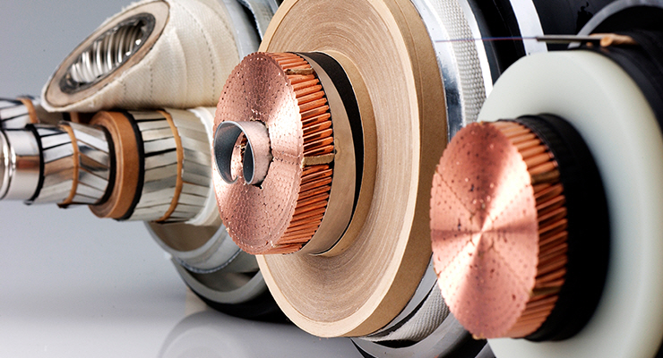
Overview of G&W Cable Accessories
In 1905 G&W introduced the first disconnectable cable terminating device.
Over 100 years later, G&W continues to create technical innovations that have improved performance and reliability. With over 100 years experience, G&W is the name you can trust for quality cable accessories. With sales representation worldwide, G&W has a proven track record for success.
G&W cable accessories are designed to accommodate cables from all manufacturers and can be created to accommodate any customer cable system. The optional mechanical shrink feature offers an easier and faster installation while reducing possible damage during installation. G&W also offers installation supervision and installation training, which can be customized to suit the audience.
G&W offers a variety of transmission cable accessories for extruded dielectric cable systems. Cable terminations are available for outdoor applications to 230kV and include porcelain or composite insulator options and premolded designs. Gas insulated substation designs are available to 230kV.
Transition cable splices and cable joints are available to 138kV and include premolded designs. All cable terminations and cable joints incorporate built-in stress control and dielectric fluid. Dry type designs are also available for maximum ease of installation.
Richie Rice has a wealth of experience in the EHV Cable Sectorand is expert and advanced skilled working on XLPE, HVDC Light XLPE, Oil/Gas Filled Cable Systems from Jointing & Terminating to VLF/ Sheath Testing. Certified from some of Europe’s leading manufacturers of GIS/ODSE Terminations & Straight / Sectionalised / Cross Bonded Joints up to 275kV.
Supervision of Cable Installations overseeing all aspects of Works & Commissioning are carried out to client’s specifications – working in the Offshore Renewable Industry on Export & Array Cabling including Jointing/Terminating & Testing on power systems up to 155kV. Trained and Certified for VLF Testing of High Voltage Cables (XLPE) up to 120kV.
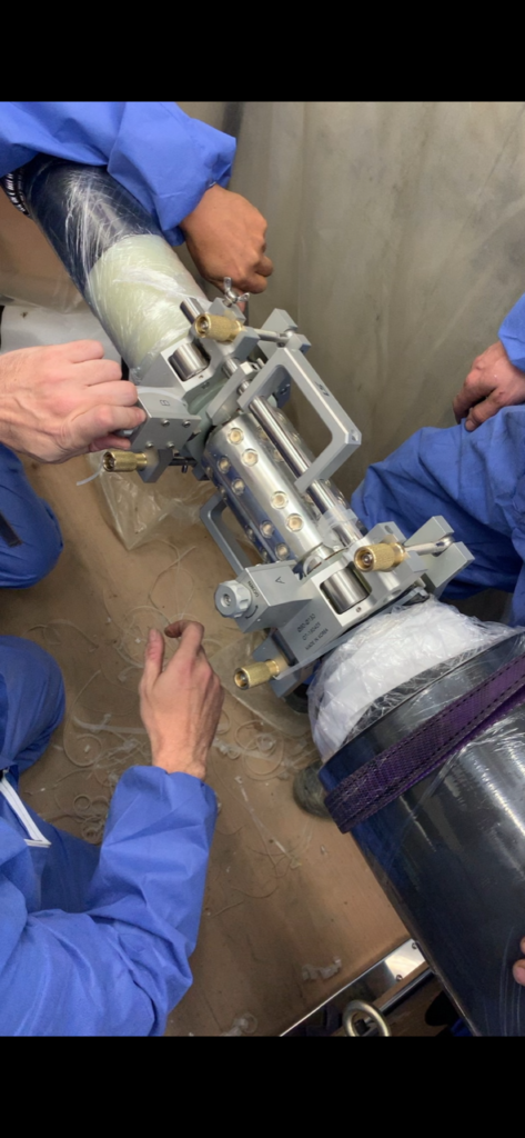
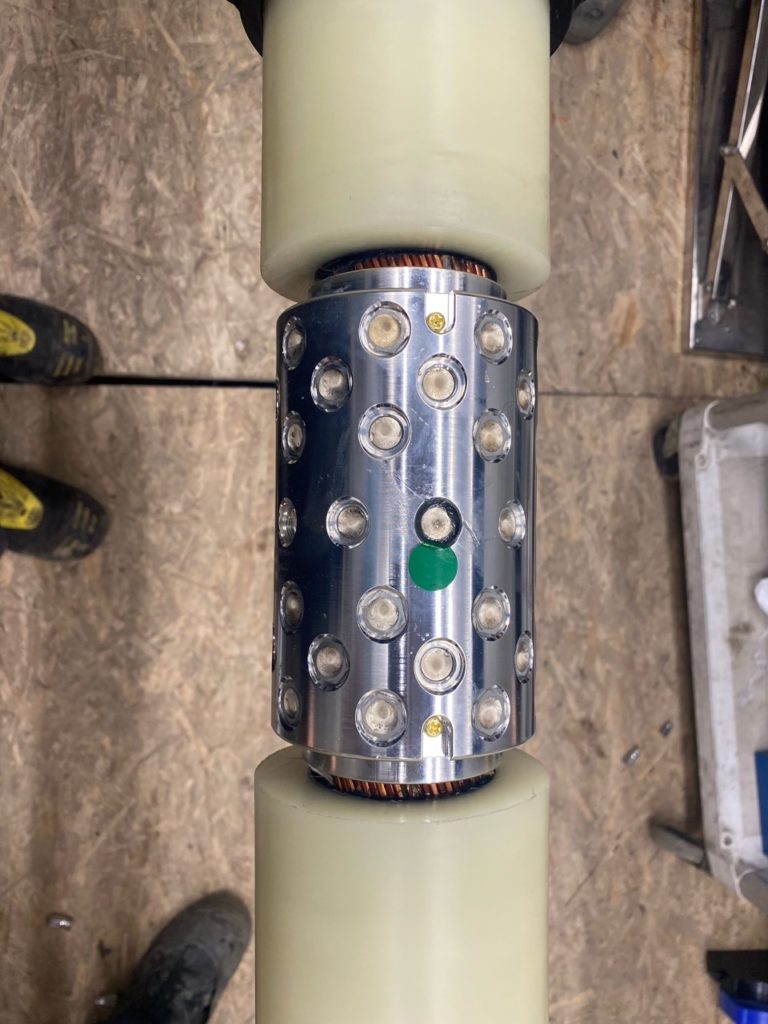
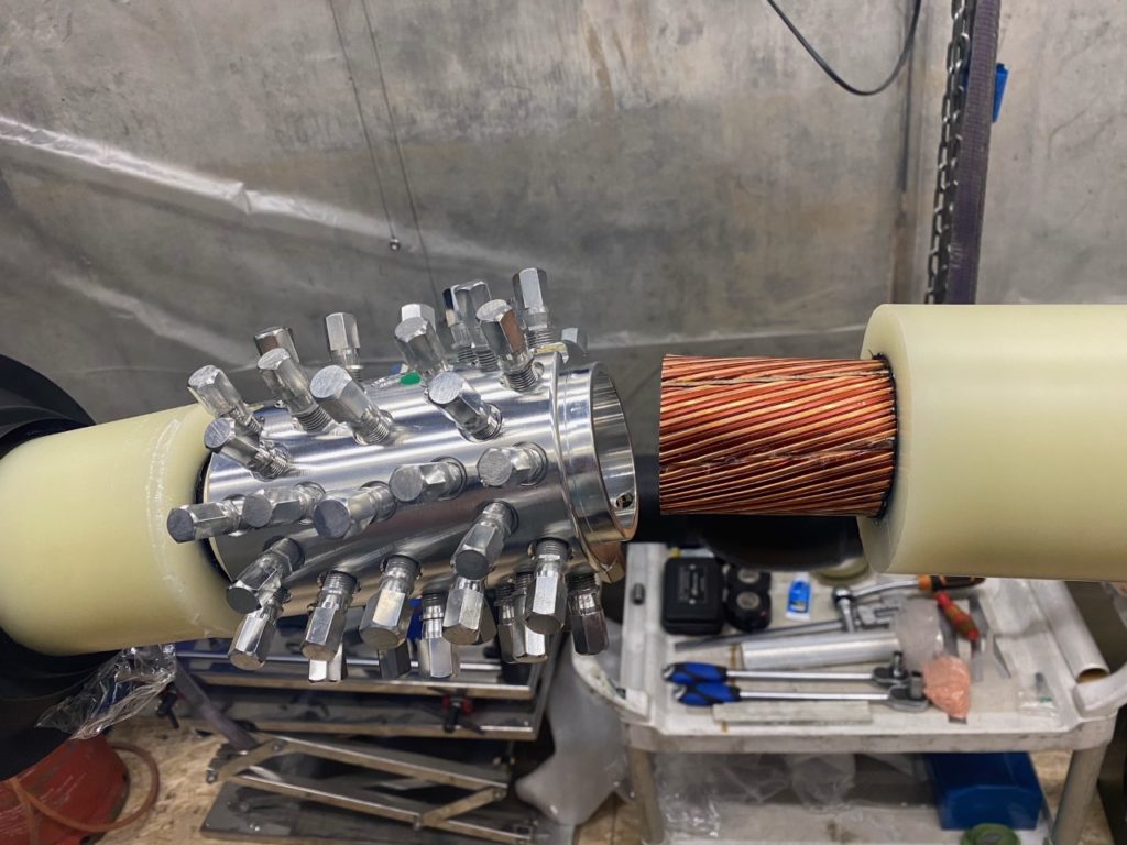
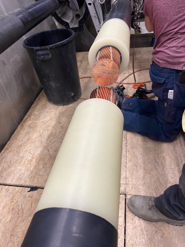
Technical Jointing Note: The paper beddings are not remove from the inner segment of the cable conductor – LS use copper particles between the cores compressed by 10no shear bolts that transfers current through these particles and this is why papers are not removed as is standard process where connectors are used for current transfer. This copper particle technique saves the cable jointer from opening cores and removing papers and the water blocking tapes – this is a significant benefit especially on Milliken Conductors.
LS Cable & Systems
Extra-high voltage cables require the power network to go underground due to continuous increase of energy demand, larger transmission capacity, reliability of energy supply, safety and aesthetic issues. Among these cables, XLPE insulation cables are used widely due to their ease of handling, simpler jointing connectivity and maintenance, outstanding electrical features and other benefits.
XLPE Cables
The basic material for XLPE is polyethylene, which is chemically transformed to cross-linked polyethylene (XLPE) through the cross-link reaction of organic peroxides. The cross-link method for polyethylene was developed in the United States during the 1950’s and has since been continuously developed for application to higher voltage cables. Higher voltages are increasingly being required and now 500kV XLPE cables have already been commercialized by LS Cables.
Thorne & Derrick
Joints & Terminations
Thorne & Derrick are national distributors of LV, MV & HV Cable Installation, Jointing, Substation & Electrical Equipment – servicing businesses involved in cabling, jointing, substation, earthing, overhead line and electrical construction at LV, 11kV, 33kV, 66kV and EHV. Supplying a complete range of power cable accessories to support the installation and maintenance of low/medium and high voltage voltage power systems:
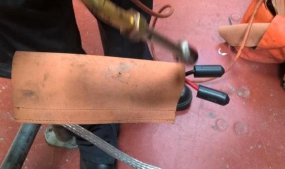
Images Courtesy: Doug Page | Work Methods and Training Instructor, EHV and HV Cable Splicer, Environmental Health Technician at Hydro One. Cable Splicer: Jeff Silliphant
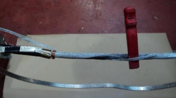
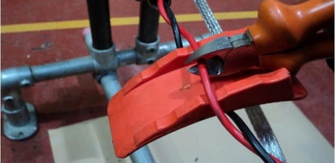
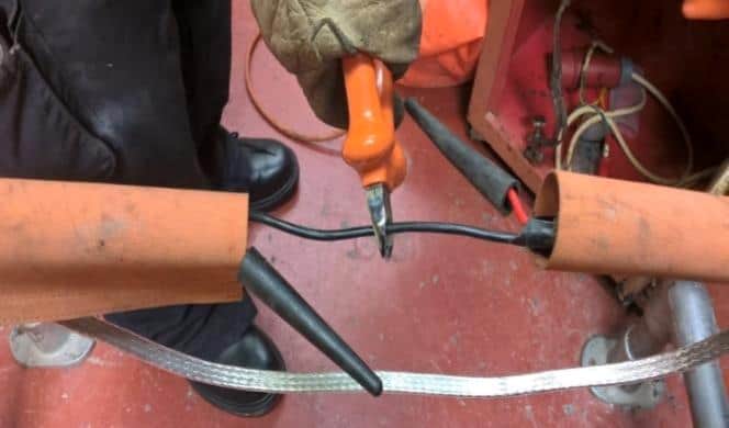
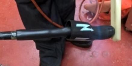
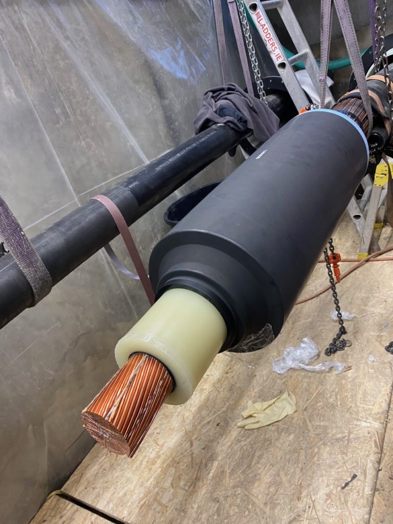
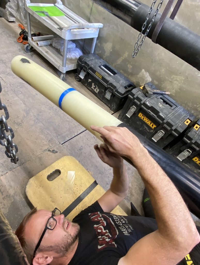
This sequence of striking photographs documents the replacement of G&W Electric Co. 2000 MCM 15kV potheads following catastrophic animal damage.
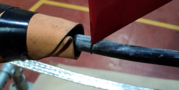
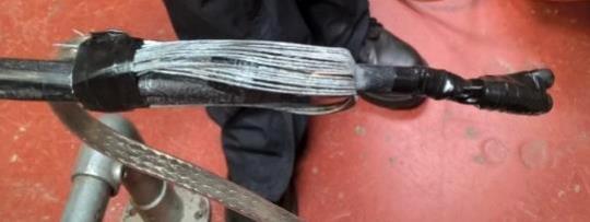
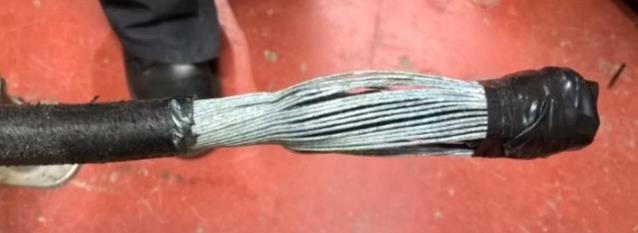
The damaged medium voltage potheads were slowly heated by the Cable Splicer sufficiently to remove the glass, then allowed to cool, so the compound could be chipped off down to the cable gland. The wipe and the cable gland were not removed – there was zero damage to the inside of the 15kV pothead, all damage was located externally.
With the compound removed, to the cable gland, the cable termination inspected and cleaned, a layer of varnished cambric tape over the cable and the void between the aerial lug and cable insulation also filled with VC. Doug comments, “because G&W potheads are manufactured with such advanced precision, all new potheads bolted directly to the gland, and directly back onto the structure perfectly.”
Did you know G&W Electric was founded in 1905 and introduced the first disconnecting porcelain pothead?
Overview of G&W Cable Accessories
In 1905 G&W introduced the first disconnectable cable terminating device.
Over 100 years later, G&W continues to create technical innovations that have improved performance and reliability. With over 100 years experience, G&W is the name you can trust for quality cable accessories. With sales representation worldwide, G&W has a proven track record for success. G&W cable accessories are designed to accommodate cables from all manufacturers and can be created to accommodate any customer cable system. The optional mechanical shrink feature offers an easier and faster installation while reducing possible damage during installation. G&W also offers installation supervision and installation training, which can be customized to suit the audience.
Subscribe now to our POWER NEWSLETTER– a monthly email circulation packed with news, projects, videos, technical tips, training information, promotions, webinars, career opportunities and white papers.
Includes access to our popular JOINTERS BLOGwith contributions from utility professionals, linesmen and cable jointers working on MV HV EHV cables and overhead lines typically at 11kV, 33kV, 66kV and up to 132kV.
15,000+ Subscribers. ➡
This article was originally posted in February 2016 to our mothballed website, www.cablejoints.co.uk
Electrical Stress
Today, we received a surprising email from Douglas Page.
Doug would not admit it but he is an acknowledged expert in the jointing and termination of EHV cables. Yes, you are Doug.
Doug has been in the industry since 1984 and is currently Work Methods and Training Instructor, EHV and HV Cable Splicer, Environmental Health Technician at Hydro One.
Expert and competent at jointing and terminating Extra High Voltage Cables (HPOF, XLPE and LPOF) and using leading Medium & High Voltage Cable Accessories from manufacturers including 3M, Raychem and Pfisterer.
This surprising email read, “a whole bunch of questions in response to recent posts by Thorne & Derrick, have asked me to explain some industry misconceptions. I am in no way trying to instruct, these are just my opinions, but hopefully they will answer some of the strange questions I have been receiving. Let me know what you think, or even if I should go down this road. The problem is, the same misconceptions have been causing cable failures for years”.
We say, steam on down that road Doug – we’ll rocket propel your content via ourLinkedIn Discussion Group and social networks. You are a thought-leader with vast experience and are attracting a definite fan-base. We see that through the Google traffic rushing into www.powerandcables.com from your Posts.
Be as flattered by the attention as we are honoured to have the opportunity to be your online voice.
R.E.S.P.E.C.T to you.
Lets pass you all over to Doug to explain some of those Electrical Stress misconceptions.
Electrical Stress Explained
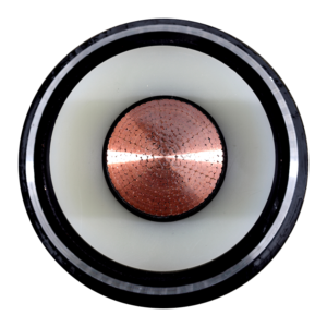
Without an insulation shield, you can see how the voltage leaves the conductor travelling through the insulation, very erratically and effectively seeking ground/earth, creating hot spots and eventually cable failures – basically this is electrical stress.
The creation of an “insulation shield” allows the stress/flux to travel very efficiently and evenly, along the cable, dissipating the “stress” evenly.The problem arises when we remove the insulation shield for cable splicing and terminating.
The abrupt end to the shield allows the different percentages of voltage to escape the insulation at a concentrated point, creating an area of extreme stress, as the voltage seeks ground/earth. This electrical stress again creates intense heat and eventually failure. In a cable splice, we are not trying to eliminate the stress, but rather control it.
In some cable splice kits gradient mastic, and “heat shrink stress control tubes” are used to contain and control the deflection of the flux lines. In other cable joint kits it could be push-on single mass control tubes. In hand tape kits, it is all built with different types of tape, put on in specific order, to very specific measurements.
With cable terminations it is different. We are not trying to control and contain, we are trying to control and dissipate as much electrical stress as possible.
Again this can be achieved in various ways. Mastic and heat shrink stress control tubing, a solid push-on mass, or again hand taping.
The type of cable termination doesn’t matter, they are all trying to achieve the same result. Control and dissipate electrical stress through deflection.
Conclusion
“Hopefully this clarifies some of the cable jointers questions. It doesn’t matter the type of cable or manufacturer, the importance around the quality of work, cannot be stressed enough, if you have a cable splicer telling you that the semi-con removal isn’t important, or the cable doesn’t need to be sanded…look elsewhere for a cable splicer,” concludes Doug.
Thorne & Derrick International are specialist distributors of LV, MV & HV Cable Installation, Jointing, Duct Sealing, Substation & Electrical Equipment – servicing UK and global businesses involved in cable installations, cable jointing, substation, overhead line and electrical construction at LV, 11kV, 33kV and EHV.
Apply a wire binder around the steel wire armours 25mm from the outer sheath cut at both end of the cable
Install the service temporary earth bond, consisting of a length insulated braid and two constant force springs, around the steel wires between the sheath removal point and the wire binders
Using a plastic small wedge and insulated side cutters, cut the individual armour wires around in the centre of the cable joint
Fold the wires back against the binder at both ends, so they are away from the working area of the cable joint
PVC tape the cut steel wire armours to the PVC either side of the cable joint
PVC Bedding Removal
Shroud the exposed armours and the continuity bond connections at both cable ends
25mm from the folded back armours, ring round the PVC bedding with a plastic Mini-Hepnyf
Note:The Mini-Hepnyf needs to be new with a clean sharp edge to ensure that the bedding can be removed without causing damage to the insulation on the cores below
Remove the bedding between the two bedding removal points, by applying gentle heat to the bedding
Note: Excessive heat will make the bedding too soft and make it more difficult to remove. Refer to Section 3.5.1 of the LV Jointing Manual
If the bedding layer is difficult to remove or if it is bonded to the core insulation, then the cable shall be made dead, prior to continuing with the bedding removal process
Core Cutting & Capping
Refer to Section 3.7.3 of the LV Jointing Manual
A PILC two or four core heatshrink pot end kit should be utilised depending on the number of cores in the SWA cables
Once the cores are exposed, test the cores to prove live and neutral
Insert a plastic cutting wedge between the cores and cut each live core in turn centrally and install a temporary cap
Finally cut the neutral core and install a temporary cap
Cut each of the live core(s) 70mm from the bedding and install the heatshrink cap provided in the joint kit, as per Section 4.10.4 of the LV Jointing Manual
Cut each of the neutral core 70mm from the bedding and install the heatshrink cap provided in the joint kit, as per Section 4.10.4 of the LV Jointing Manual
Completing The Pot End
Remove the temporary earth continuity bond and any temporary shrouding
Allow the heat caps to cool, apply two half lap layers of PVC tape over the cores
Fold the steel wires back over the previously applied PVC tape, trim them to the same length as the phase and neutral cores
Apply two half lap layers of PVC tape over the wire armours and tinned copper mesh, make sure all sharp edges are covered
Slide the mastic coated heatshrink tube over to the 60mm of sheath abrasion and shrink into place ensuring a good water seal. As per Section 4.10.4 of the LV Jointing Manual
Slide the mastic coated large heat shrink cap over the previously shrunk tube and shrink in place, starting at the sealed end, before working towards the open end. To prevent the
cap sliding off hold in place using an insulated wedge
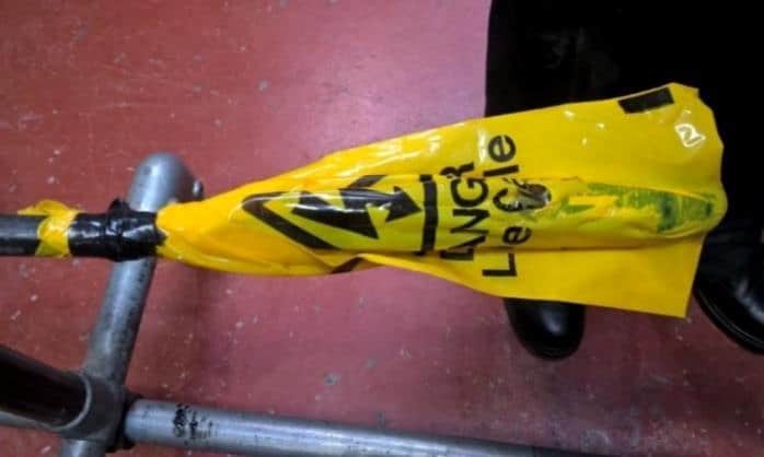
Allow to cool before fitting the yellow plastic safety bag in place
Once the pot end has cooled, place the yellow bag over the joint, ensure that the hazard symbol is on the top and fix in place with PVC tape
LV HV Electrical Cable & Power Distribution Systems up to 66kV – we are highly customer responsive and absolutely committed to providing a world-class service.
Contact our UK Power Team for competitive quotations, fast delivery from stock and technical support or training on all LV-HV products.
INDUSTRIAL LABEL PRINTING SOLUTIONS When clear, durable and professional identification is required across control panels, cable systems, production facilities and industrial installations, print quality, reliability and ease of use are critical. Cembre industrial label printers are designed to support...
HIGH VOLTAGE JUNCTION BOXES & ENCLOSURES When high-voltage power distribution and cable termination are required, safety, enclosure integrity and long-term reliability are critical. HV Junction Boxes and Electrical Enclosures manufactured by Abtech are engineered for the safe distribution, cable termination and protection...


 The problem arises when we remove the insulation shield for cable splicing and terminating.