Driven earth rods manufactured from solid copper and bonded with copper are available from stock – contact Thorne & Derrick
There are three types of LPS Earthing systems types A, B and Foundation Earth Electrodes
Type A – The conventional LPS Earthing system using
vertical or horizontal electrodes such as
copperbond Earth rods or copper tape
Type B – The ring electrode sited around the periphery of the structure
Foundation Earth Electrodes
The foundation electrode system installing the conductors in the concrete foundations of the structure.
Type A Earthing Arrangement
This is the conventional type of LPS Earthing System where earthing rods are used to form the earth electrode and usually each down conductor, such as copper earthing tapes, are connected to an earth rod.
The type A earth termination arrangement is suitable for low structures (below 20 metres in height) or an LPS with rods or stretched wires. For an isolated LPS the British Standard BS EN 62305 recommends a type B earthing arrangement where the structure is housing extensive electronic systems.
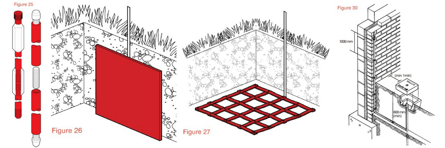
The type A arrangement uses vertical or horizontal earth electrodes. Practically it uses both connected to each down conductor, installed outside the structure (below the foundation) to be protected and housed in a plastic or concrete pit for ease of inspection (figure 30).
Lightning Protection – Copper Earthing Equipment
The minimum number of electrodes is 2.5 metres, regardless of the perimeter of the structure/class of LPS.
The minimum length of each earth electrode at the base of each down-conductor is specified in BS EN 62305 and the table below.
Minimum length l¹ of each earth electrode according to class of LPS
It is 11 for horizontal electrodes – usually copper tapes.
Or
0.511 for vertical copperbonded rods or solid copper rods. Or
>11 in the case of a lattice mat measuring the total length of the conductor in the earth mat.
Or
If copper plates are to be used the surface area of the plate should be at least equal to either.
The surface area of the length of earthing conductor that would need to be used to satisfy the requirement for a vertical electrode 0.511.
Or
The surface area of the length of earthing conductor that would need to be used to satisfy the requirement for a lattice mat electrode 11.
Or
If using vertical and horizontal electrodes, the individual earthing electrode lengths should follow the 0.511 and 11 principle respectively.
Type A earth electrodes should be installed so that the top of the earth rod is 0.5 m below the surface, this distance is to reduce the effects of step potential at ground level.
The earth rod should be housed in an inspection pit, commonly concrete or plastic for ease of inspection and registering the location during and after installation figure 30.
Full range of copper earth tapes available from stock in range of widths and thicknesses.
Type B Earthing Arrangement
The type B Earthing arrangement is most suitable for:
The type B earthing is recommended as either a ring conductor outside the perimeter of the structure which it’s recommended should be in contact with the soil for at least 80% of its total length.
The alternative is to use a foundation earth electrode which can be in a mesh form.
It is recommended that the type B earthing network whichever method is chosen should be integrated as a meshed network buried to a minimum depth of 5 rats.
The reinforced concrete floor slab can be used around the structure.
If the required resistance cannot be achieved by this method the vertical or radial earthing electrodes can be added to the network.
For ease of testing after installation an inspection pit with an earth bar should be installed where the legs of the ring and conductor routing onto the ring from the each test clamps join (figure 31).
Any internal down conductors should be connected to the internal foundation using a test clamp for ease of maintenance.
Foundation Earth Electrodes
Once all the services are connected its unlikely the installer will be able to measure the earthing resistance of the foundation earth in isolation.
The use of the foundation as an earth electrode is allowable only where the reinforcement network is below any insulating or waterproof membrane.
Where a foundation is used as an earth-termination the reinforcing bars must be clamped or welded together to ensure electrical continuity.
Alternatively an additional meshed network of conductors can be installed to ensure continuity. The additional network should be connected to the reinforcing bars by clamps or welded joints every 20 m throughout the system.
The earthing system whether using reinforcing bars or additional conductors or a combination of both must be connected to every down conductor and internal steelwork.
Internal Lightning Protection System
The internal LPS is important to fully complete the installation to fulfil the requirements of BS EN 62305.
The main reason for installing an internal LPS is to avoid any dangerous sparking within the building.
The sparking is caused by current flow and the difference in potential between internal conductive components such as steelwork and the external LPS on the outside of the building or from the use of the internal steelwork as part of the LPS.
The earthing system whether using reinforcing bars or additional conductors or a combination of both must be connected to every down conductor and internal steelwork.
T&D are Specialist Distributors to UK Distribution Network Operators (DNO’s), NERS Registered Service Providers, ICP’s and HV Jointing Contractors of an extensive range of LV, MV & HV Jointing, Earthing, Substation & Electrical Eqpt – this includes 11kV/33kV/66kV cable joints, terminations and connectors for both DNO and private network applications.
Contact our UK Power Team for competitive quotations, fast delivery from stock and technical support or training on all LV-HV products.
The LPS (Lightning Protection System) is required to:
Intercept the lightning strike (the air termination network)
Conduct the lightning strike safely to ground (using down conductors, such as copper earth tapes)
Disperse the strike safely into the earth (earthing)
Whilst the structural protection is there to conduct a strike safely to earth this is normally combined with internal protection to prevent sparking within the structure ensuring all metallic services are at equipotential (bonding)
The designer of the LPS should ensure that:
The safest path to earth is the LPS
The risk of sparking whilst the strike is conducted safely to earth is minimised (separation distance/s)
The risk of voltage differential whilst the strike is being dissipated in the ground safely is minimised (step & touch potentials)
The designer of the LPS has to gather all the relevant information to ensure the earthing system design is as safe as possible within any economic restraints:
A designer may find it impractical to fully install the desired LPS
A designer may not be able to justify the cost of providing the desired LPS
A designer may consider using the metal roof or reinforcing bars within a building as the safest and most economic design
A designer may consider extra bonding and surge protection devices are required to protect the internal space, especially if the space houses sensitive electronic equipment
A designer may consider a building of such a high risk that additional measures are taken to ensure safety, possibly a flour factory or a building with a combustible roof, in these cases the LPS system may have to stand off the building
Contact Thorne & Derrick for largest UK stocks of copper earth tapes.
Criteria For The Protection Of Structures
The level of protection/Lightning Protection Level (LPL) applied to the structure is identified by the risk assessment.
Lightning Protection System (LPS) Level
LPL I requires a Class I
LPS LPL II requires a Class II
LPS LPL III requires a Class III
LPS LPL IV requires a Class IV LPS
Design of The LPS General Considerations
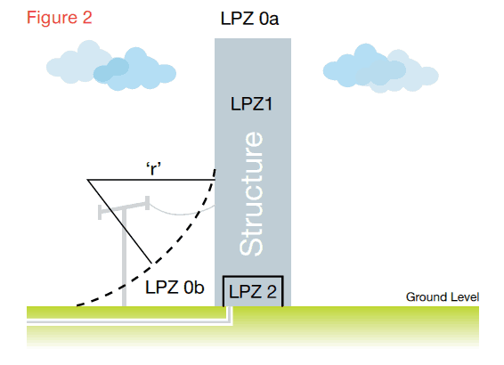
To help the earthing system designer, the threat of lightning to a structure or building can be defined in lightning protection zones requiring protection and the type of lightning strike likely to enter the building shown in Figure 2.
S1 – Strike directly to the structure
S2 – Strike on the ground near the structure
S3 – Strike to a service connected to the structure
S4 – Strike on the ground near a service connected to the structure
LPZ1 – The protected zone inside the building, the zone where current is limited by current sharing and SPD’s at the boundary (less the separation distance)
LPZ Oa – At risk from the full lightning strike and the full lightning electromagnetic field
LPZ Ob – Not at risk from a direct lightning strike considering the protected area through the rolling sphere but at risk from the full lightning electromagnetic impulse. (LEMP)
LPZ 2 – Protected zone with further dampened magnetic field
The LPS designer should ensure everything to be protected falls inside the LPZ Ob range in figure 2.
The bonding measures employed need consideration at the design stage
The earthing design should consider fully the step and touch potential risks
The requirements for Surge Protection Devices (SPDs) on incoming mains and conductive services should be considered in accordance with the risk assessment carried out for the structure LPS requirements
Where combustible wooden type materials are present a distance of 0.15 m should be maintained between the LPS conductors and the roof, for any other combustible surfaces a distance not less than 0.10 m is required
Some structures will have reinforced sections with expansion joints, if the designer of the LPS considers electronic equipment within the building is at risk then bonding conductors should be provided across the joints to provide low-impedance potential equalization. The separation distance between the bonds should not be more than half the distance between the down conductors
Natural components within/part of the structure such as the rebars can be made use of provided they will always remain an integral part of the structure conforming to the requirements below
Manufacturer by high conductivity and purity copper the range of earth tapes provide effective protection to buildings and substations
Using natural conductors as part of the LPS
The building’s natural components, metal roof, rebar, steelwork etc can be considered as part of the LPS provided they meet the minimum criteria shown in Table 1.
Material for LPS levelI to IV
Prevents puncture, hot spots or ignition. minimum thickness (mm) (ta) requirement
Only for metal sheets where preventing puncture, hot spots or ignition is not important. minimum thickness (mm) requirement (tb)
Lead
2.00
Stainless Steel
4
0.50
Titanium
4
0.50
Copper
5
0.50
Aluminium
7
0.65
Zinc
0.70
The reinforcing bars within the concrete structure can be used as a natural component of the LPS provided they are electrically continuous by either welding or clamping the joints.
The re-bars are considered as electrically continuous provided that the major part of interconnections of vertical and horizontal bars are welded or otherwise securely connected by clamps conforming to BS EN 50164 standards.
The connecting rebar must overlap and be clamped using rebar clamps or welded to a minimum of 20 times the diameter of the rebar as shown in figure 3. (Welding to be done on either side of the rebars.)
Example of a rebar joined by clamps
To test the continuity of the reinforcing bars the resistance between the re-bar connection to the air termination network and the rebar connection to the earthing network should be measured, the resistance should not exceed 0.252, otherwise proprietary down conductors will be required.
In order to provide a connection to the rebar from outside the concrete a cast-in earth plate can be used as shown in figure 4, the earth point sits in the wall (or within an enclosure) providing a connection to the re-bar with a welded copper tail attached to the earth point and to the re-bar with propriety clamps.
Earth point sits in the wall providing a connection to the rebar
The designer of the structural LPS has 4 main criteria to consider:
The roof termination system
The down conductor configuration
The Earth Termination network including equipotentialization and the risk of step and touch potential (equipotentialization on its own is not effective in reducing the risk against touch voltages)
Bonding (creating a euipotential zone across all zones, Oa, Ob, Z1, Z2)
The diameter of the sphere depends on the class of LPS selected/determined.
Class LPS
Sphere Radius
I
20
II
30
III
45
IV
60
Complete range of earth bars with connection options and number of cable termination ways to provide effective common isolation point.
Methods Of Designing The Air Termination Network
1 – The rolling sphere
2 – The protective angle design
3 – The mesh design
The Rolling Sphere Method
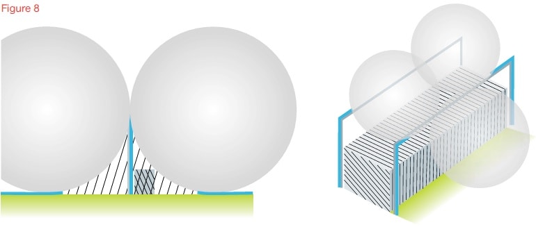
This method simply rolls a sphere around the building to be protected, wherever the sphere touches the building dictates where the protection measure is to be applied, where the sphere does not touch the building, this is accepted as a protected area, this method can be used to design the LPS on complex structures or where the LPS has to be isolated.
The rolling sphere method is especially relevant on complex structures with many different levels, this method easily identifies the protected space and where protection measures should be applied to the structure.
Examples of the air termination system using the rolling sphere technique
Designing The Lightning Protection System (LPS)
The Protective angle design
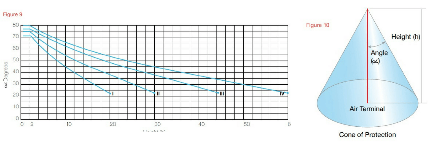
The Protective Angle method in figure 10 is only used on simple structures or for small sections of larger structures.
The Protective Angle design method cannot be used where the part of the structure/service to be protected is higher than the radius of the rolling sphere corresponding to the class of LPS.
The level of LPS dictates the angle of protection depending on the reference height, see figure 9.
This method of earthing system design is an alternative method based on the rolling sphere and is not offered to give a wider range of protection than the rolling sphere.
In figure 9 the height limits for designers are clear and correspond to the radius of the rolling sphere.
Protective Angle Design
The Mesh design
The most commonly used method, is usually employed where the structure is simple, a square or rectangular building or typical house or block of apartments with a sloping roof, the mesh method is for protection in zone OA.
The mesh design protects the whole area if conductors are positioned on the edge of the roof where the slope of the roof exceeds 1:10.
Protective angle design to protect free standing equipment on the roof of a building
On structures up to 60 metres in height, only consider applying an air termination system to the roof and provide protection to points, corners and edges of the structure. No lateral air termination is required regardless of the class of LPS.
On structures higher than 60 metres lateral air termination systems should be applied to the top 20% of the structure relevant to its class of LPS (or at least conforming to class IV LPS).
The mesh of earth conductors are installed on the roof, the earth conductor must be at the edge of the area to be protected and for metal items such as air conditioning units that protrude above the conductor, the protective angle design should be applied for protection.
The size of earth mesh required is defined by the level of LPS determined/selected
T&D are Specialist Distributors to UK Distribution Network Operators (DNO’s), NERS Registered Service Providers, ICP’s and HV Jointing Contractors of an extensive range of LV, MV & HV Jointing, Earthing, Substation & Electrical Eqpt – this includes 11kV/33kV/66kV cable joints, terminations and connectors for both DNO and private network applications.
Contact our UK Power Team for competitive quotations, fast delivery from stock and technical support or training on all LV-HV products.
Uploaded By - Chris Dodds (Thorne & Derrick Sales & Marketing Manager)
Press Release: Lucy Zodion
Street Lighting Cut Outs
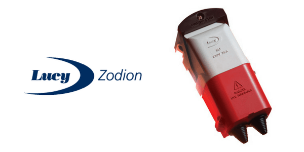
Lucy Zodion Ltd have secured sole approval for street lighting cut outs in the Western Power Distribution (WPD) Network – the Lucy SLCO cut outs are now approved by all UK Distribution Network Operators (DNO’s).
Lucy Zodion Ltd, leading UK manufacturer of cut-outs, controls, feeder pillars and street lighting isolators, is pleased to announce its street light cut outs(SLCOs) are now part of the G81 specification framework, won by Lucy Group for industrial and commercial underground connected loads up to and including 11kV.
WPD exclusively specifies a number of Lucy Group secondary power distribution solutions throughout the East and West Midlands, South West and Wales regions.
The updated specification means that Lucy Zodion’s street lighting cut-outs are now approved by every Distribution Network Operator (DNO) throughout the UK – the Lucy Titan range of cut outs include several market-leading design features such as the cam lever handle that enables effortless release of the fuse carrier in one movement or the generous cabling space to terminate a wide variety of conductor types and sizes. Where dual or triple cable entries are required, a choice of either insulated or brass cable gland plates is available, the latter being specifically provided for the termination of armoured SWA cables.
➡ For further information about how Lucy Zodion provide control and power distribution products for street lighting applications, please review the Lucy Titan (Cut-outs) and Lucy Trojan (Isolators) ranges of products.
Should you require any technical support or have any commercial requirements about G81 Approved 11kV/33kV Cables & Accessories please do not hesitate to contact Thorne & Derrick Sales Team.
Lucy Titan2 Street Lighting Cut Outs
Furthermore, Western Power Distribution (WPD) specifies Lucy Zodion SLCOs onto contract for exclusive use within their region.
The G81 standard included cut-outs for street lighting control are:
Lucy THM0048847 SLF IPC Type 1 Cut Out (SNE) HEX Drive Clear Cover
Lucy THM0041767 SLF IPC Type 2 Cut Out (CNE) HEX Drive Clear Cover
Lucy Zodion is one of the UK’s leading manufacturers of street lighting cut outs and is dedicated to adhering to industry standards, as well as its own quality procedures.
Lucy Zodion’s SLCOs are compliant with BS7654, which covers all aspects of the cut out from the materials in which it is manufactured, to a series of tests relating to temperature, ingress protection, current and mechanical strength.
Other features of the approved products include clear covers, enabling quick and safe inspections, Insulating Piercing Connectors (IPC) to protect against insulation shrink back, as well as many more high quality benefits associated with the Lucy Zodion SLF range.
Street Lighting Cut Outs | Isolators | Feeder Pillars
THORNE & DERRICK
T&D are Specialist Distributors to UK Distribution Network Operators (DNO’s), NERS Registered Service Providers, ICP’s and HV Jointing Contractors of an extensive range of LV, MV & HV Jointing, Earthing, Substation & Electrical Eqpt– this includes 11kV/33kV/66kV cable joints, terminations and connectors for both DNO and private network applications.
Contact our UK Power Team for competitive quotations, fast delivery from stock and technical support or training on all LV-HV products.
uploaded by Chris Dodds – Thorne & Derrick Sales & Marketing ManagerShoveIt Tools | Largest UK Stocks | Contact Us for a Quotation
Shoveit
Push Pull Tools
Prevent Hand Injury & Pinch Point
Prevention Of Workplace Hand Injuries
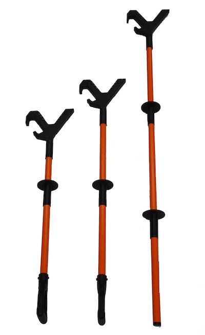
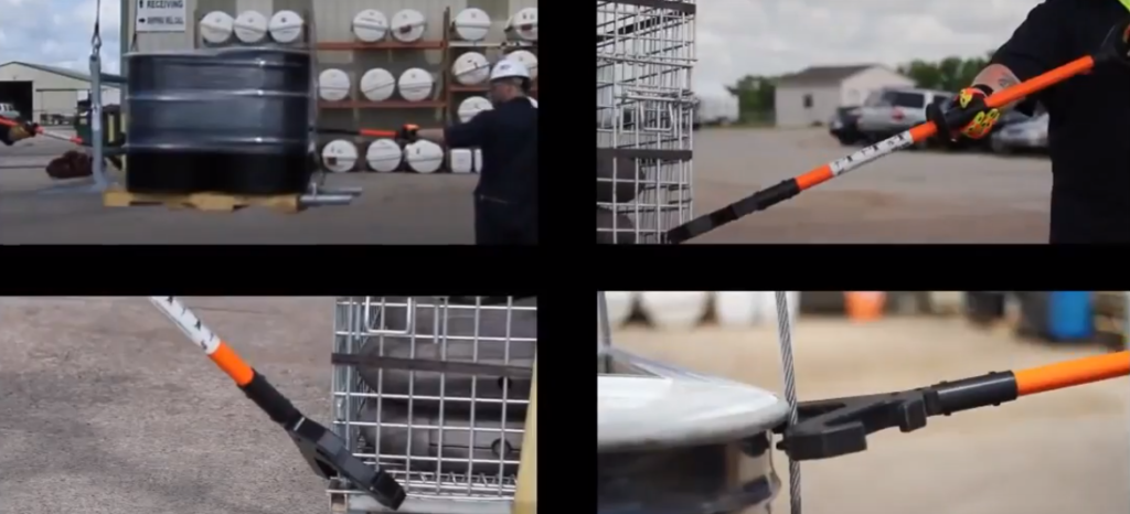
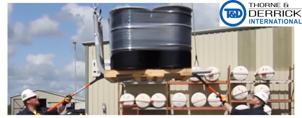
Thorne & Derrick represent and distribute the ShoveIt Hand Safety Tool in the UK – the non-conductive hand tool substantially reduces hand and finger injuries by avoiding pinch points and other hand related safety issues while working with suspended loads and materials handling on job sites.
This mitigation measure, some may say “finger-saver”, safeguards employees by minimising hand and finger injuries – this proactive control measure protects against unnecessary workplace hazards. Gloves can limit severity but not remove risk.
Pinch Points & Hand Protection
A pinch point is commonly defined as any point where it is possible for a body part to be caught between moving and stationary plant or equipment. Pinch points are found in many places throughout a workplace.
Work tasks such as equipment maintenance, lifting materials, guiding loads, assembly line work and hoisting or hooking up trailers are just a few common tasks where pinch points are a common hazard.
The physical forces applied to the hand caught in a pinch point can vary and cause injuries ranging from bruises, cuts, fractures and scalping to mangled and amputated body parts, and even death.
The ShoveIt Hand Safety Toolis used to promote hand injury prevention, whether minor or serious, in the electric utility power and transmission distribution sectors – the tool is also widely used in the oil and gas, rail, renewables, offshore and marine and construction industries to prevent “crush-effect” or pinch point inflicted hand injuries.
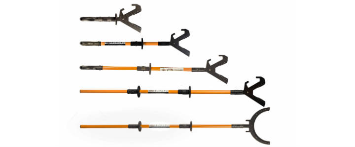
The non-conductive tool is available in standard lengths 42″, 50″ and 72″ with custom lengths available upon request subject to minimum order quantity – refer to the download below.
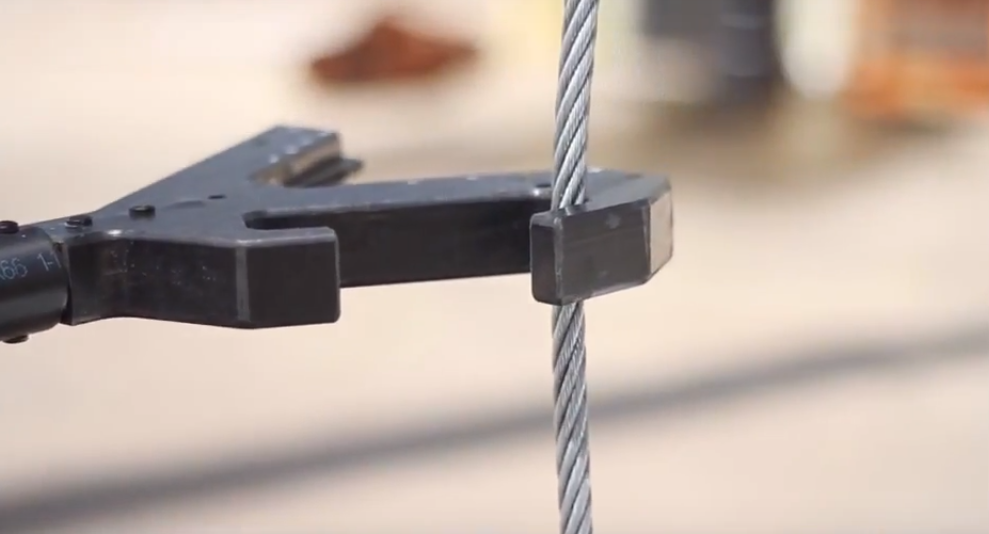
ShoveIt Hand Safety Tool is a non-conductive tool with a V-shaped hand that is designed to:
Push against flat surfaces, corners or rounded edges of suspended loads
Move pipes and tubulars with the “V” shaped end
Grab slings and taglines with the hooks
Manouevre suspended loads in MV HV EHV substations and switchyards
ShoveIt
Push Pool Tools
The range of Push Pull Tools manufactured by the Hand Safety Tool Company and distributed by Thorne & Derrick provide significant Health & Safety Improvementsaround site where “pushing and pulling” operations such as handling deliveries or loading/unloading in yards is commonplace. This download produced by the UK HSE enables the Risk Assessment according to Load Weight, Operation Frequency, Push/Pull Distances and other impacting factors – the range of tools to keep hands off loads, enable “hands-free” lifting, mitigate risk of load handing and prevent hand or finger injury are available in the UK from Thorne & Derrick.
ShoveIt Hand Safety Tool
The V-shaped head features a rubber lining to prevent slippage when using the hand tool.
The tool shape also allows users to safely guide drill pipe, casing and other tubulars without having to directly use your hands.
The opposing grab hooks help the user manouevre tag lines and slings as suspended loads.
A slip resistant hand grip is positioned halfway down the length of the tools. A second slip resistant hand grip is positioned halfway down the length of the tool. A second slip resistant hand grip is available on the 72″ model whilst the 42″ and 50″ are finished off with a D shaped handle. The grips are ergonomically designed to provide the user with maximum pushing and pulling control.
No metal parts are used in the manufacture of the ShoveIt hand safety tool – the tool is entirely non-conductive.
Non-conductive tools are used for a number of applications:
Grab taglines
Grab sling legs
Land suspended loads
Guide suspended loads
Guide tubulars
LHR ShoveIt Hand Safety Tool
New Features
Rubber lining added to “V” to improve grip
Opposing grab hooks to help with the maneuvering of cable slung loads
ShoveIt Hand Safety Tool available in 42in, 50in and 72in lengths
LHR ShoveIt Hand Safety Tool
Product Range
LHR ShoveIt Part Number
Non-Conductive Tool Description
SHST42
42 inch
SHST50
50 inch
SHST72
72 inch
SHST72T
72 inch w/Single Side Hook
SHST72TEFLON
72 inch w/Teflon
Should you require any further information, quotation or would like to place an order for the ShoveIt Hand Safety Tool please do not hesitate to contact Thorne & Derrick.
➡ NOTE:ShoveIt hand safety tools must NOTbe used to pry or lift any item.
➡ Qualified and approved safety equipment and/or PPE should be used while using the ShoveIt tool.
Thorne & Derrick International are specialist distributors of LV, MV & HV Cable Installation, Jointing, Duct Sealing, Substation & Electrical Equipment – servicing UK and global businesses involved in cable installations, cable jointing, substation, overhead line and electrical construction at LV, 11kV, 33kV and EHV.
Cable Stripping Tools For LV Cables – Alroc DBT Cable End Strippers
uploaded by Chris Dodds - Thorne & Derrick Sales & Marketing Manager
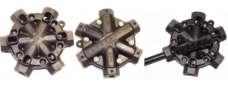
Alroc DBT cable end strippers enable the user to remove the outer sheath insulation of secondary distribution LV Low Voltage cable ranging from 16sqmm up to 150sqmm. The ruler engraved in the cable jointing tool sets the length of the insulation to be removed.
The DBT cable end strippers are compact, light and heavy duty and are available for 6 different cable sections – 16-25sqmm, 35-54.6sqmm and 70-150sqmm.
Other sections are available upon request.
Cable Stripping Tools For LV Cables
Tool Capacity
Diameter: ø7.5 – 18 mm, ø0.295 – 0.709 in
Sections (sqmm): 16 – 25 – 35 – 54,6 – 70 – 150
35sqmm max length:55 mm / 2,165 in
54.6sqmm max length: 70 mm / 2,756 in
Certifications approved by ERDF
Part Number: Alroc DBT
Alroc DBT Cable End Strippers
Tool Dimensions
Length 130 mm
Width 130 mm
Height 40 mm
Weight without box 0.23 Kg
Alroc offer a range of low voltage cable preparation splicing and stripping tools suitable for use prior to cable joint and termination installation.
Alroc Tools are used and recommended by PFISTERER for MV HV cable preparation of cables prior to installation of their market-leading CONNEX plug terminations for connection to gas insulated switchgear and substations.
Thorne & Derrick
T&D are Specialist Distributors to UK Distribution Network Operators (DNO’s), NERS Registered Service Providers, ICP’s and HV Jointing Contractors of an extensive range of LV, MV & HV Jointing, Earthing, Substation & Electrical Eqpt– this includes 11kV/33kV/66kV cable joints, terminations and connectors for both DNO and private network applications.
Contact our UK Power Team for competitive quotations, fast delivery from stock and technical support or training on all LV-HV products.
Celebrating Charlie & Ella’s Level 4 Sales Executive Apprenticeships At Thorne & Derrick International, we are proud to champion talent development and recognise the dedication required to achieve professional growth. We are therefore delighted to congratulate Charlie Baines and...
Thorne & Derrick will be Exhibiting at Solar & Storage Live UK 2026 at the NEC Birmingham from 22nd–24th September, showcasing our support for HV Cable Accessories, Joints, Terminations, Separable Connectors, Cable Tooling and Grid Connection Products used across...