Thorne & Derrick, the UK Specialist Distributors for Nexans Power Accessories UK, would personally like to invite you to attend the ‘Online Training Session’to help us celebrate the 4th birthday of their Normanton Training Centre. Nexans established industry-leading Training Courses provide refresher and continuous development training for existing Jointers using a combination of theoretical and practical test elements.
Presented by James Addy (Technical Manager) and Kristof Rottiers (Technology & Services Manager – Nexans), together they will cover the Jointer Training Courses available at their UK centre which is specifically tailored to enable the upskilling of cable jointers from LV to MV 11kV, 33kV and 66kV.
Competency Test demonstrations will be carried out and you will get the chance to discuss your Jointer Training requirements with the experts.
Thorne & Derrick stock and distribute the full range of Medium Voltage Cable Accessories manufactured by Nexans in heat shrink, cold applied slip-on and EPDM rubber technology – this includes MONO Terminations, JTS Joints and Euromold Connectors up to 33kV.
Contact our trained team of Technical Sales Engineerfor competitive quotations and delivery from stock.
Battery Energy Storage System
Eclipse Power Networks were appointed by Sembcorp Energy UK (Formally UK Power Reserve) as the Independent Distribution Network Operator (IDNO) for the 50MW Battery Energy Storage System Site (BESS) at Cowstead in Sheerness, Kent.
Cowstead Battery Storage
The battery energy storage siteis connected directly to the UKPN network via their existing 132kV Overhead Line (OHL) Network. A new UKPN 132kV disconnector was required to be installed beneath the OHL Point of Connection (PoC) as part of the contestable works.
Eclipse Power adopted the 132kV cable from the new disconnector to the 132kV metered Point of Supply (PoS).
An IDNO 132kV substation, incorporating 132kV earth switches, disconnector and dead tank circuit breaker, completed the IDNO adopted network assets that feed a client adopted 132/33kV 40/50MVA ONAN/ONAF transformer and 33kV GIS substation adjacent to the IDNO compound.
The Sembcorp network assets facilitate their 50MW BESS assets, which nearly doubles their UK battery storage portfolio.
Battery Energy Storage System
Project Challenges
The project had consent challenges which Eclipse helped to resolve quickly and efficiently. Such challenges are unlikely to have been resolved as efficiently, had the client elected to use the DNO to adopt the Contestable Works.
What is an IDNO?
Independent Distribution Network Operators (IDNOs) are OFGEM licensed companies that develop, design, own, operate and maintain local electricity distribution systems within the DNO network.
IDNOs are connected to Distribution Network Operators (DNOs), either directly, or through other IDNOs. They carry power to homes and businesses around Britain. Unlike DNOs, they’re not bound to any specific geographical region and can therefore offer their services to a wider range of customers.
IDNO Vs DNO
If you are looking to use an IDNO on your next project, please get in touch with Eclipse Power Networks:
Eclipse Power Networks are a licensed Independent Distribution Network Operator (IDNO) who provide clients with an effective alternative to using the local Distribution Network Operator (DNO).
Working within the UK Energy industry, we design, own, operate and maintain licensed electricity distribution networks across the UK.
Our team of specialist Electrical and Civil Engineers have extensive experience of working within the electricity supply industry at voltage levels up to and including 132kV, based out of our Head Office in Buckinghamshire.
We can offer Developers, Contractors and ICPs several significant benefits over the standard DNO connection to the National Grid.
We work across a variety of sectors including (but not limited to):
T&D are Specialist Distributors to UK Distribution Network Operators (DNO’s), NERS Registered Service Providers, ICP’s and HV Jointing Contractors of an extensive range of LV, MV & HV Jointing, Earthing, Substation & Electrical Eqpt – this includes 11kV/33kV/66kV cable joints, terminations and connectors for both DNO and private network applications.
Contact our UK Power Team for competitive quotations, fast delivery from stock and technical support or training on all LV-HV products.
Special thanks to Emily Sotupo Marketing Co-ordinator from EasyPower LLC for the kind permission to republish – view the original article click here
Arc Flash Studies
Each year we see dozens of arc flash studies ranging from first attempts to submittals from seasoned veterans in the industry. With an eye towards improving the overall results in the field, we offer this list of “Ten Most Common Errors.” This is not a criticism of anyone or any group; it is more of an effort to bring some insight to areas that may not be that well understood, including changes in the standards, the phenomenon of arc flash, and the application of analytical tools toward that end.
#1 – The Lack of Understanding the “Arc Flash Paradox.”
The counter-intuitive nature of the arc flash hazard tends to impede the acceptance of arc flash as a hazard by some of us with a long history in the industry. Put simply, within the same system you can have buses that have high current and high arc incident energy AND other buses that have lower current but that calculate a higher arc incident energy. Incident energy has a significant relationship to the time required to clear the arc.
Comparing Bus-4 to Bus-2 in the example below, Bus-4 has a higher incident energy in spite of having available fault current at Bus-4 that is only 20% of the fault current available at Bus-2. The length of time to clear the arc in this case has a significant bearing on the arc flash calculation.
#2 – “Infinite source” is Not the Worst Case
Nor should it be used in place of actual utility data when calculating arc flash results. Often times, the local utility company cannot or does not respond to a request for short circuit data as required for an arc flash hazard assessment. From the early days of power system design, the engineer responsible for the electrical system was tasked with the requirement to have the system be able to safely protect itself against the worst-case short circuit current that it could possibly see from the utility source. The concern was due to the short circuit rating for each piece of equipment in the system.
Each piece of equipment needed to be able to survive in the case of a short circuit fault. The results of an equipment duty analysis will determine if any system element has the potential for being over-stressed in the case of a worst-case fault at that location.
In that case, using an infinite source would be valid to determine system integrity. In the case of arc flash analysis, however, the use of a higher short circuit current value than is really expected could potentially yield a lower result for arcing incident energy since the higher current value of the infinite source would cause the protective devices to trip quicker than the same circuit exposed to actual or estimated fault current at the utility connection. This can be shown in the framework of an EasyPower study by using the Scenario Manager to compare results.
#3 – Not all buses are created equal!
The long-awaited release of IEEE 1584-2018 promised improved alignment between model results and the test data upon which the model is built. Part of this improvement is the inclusion of a number of parameters that were not included in the original arc flash calculation method. Included in the updated standard is a table of typical values for each of these parameters along with equipment type and different voltage levels.
It is therefore a good practice to ensure that the data collection team can identify the type of switchgear or panelboard and at the same time recognize if there is a significant difference between the typical values listed in the standard and record the actual values for:
Working distance
Electrode gap
Enclosure size
Electrode configuration
In EasyPower, the default values for each of these parameters are included in the Arc Flash Hazard Default table in the Device Library. If the actual system diverges from the default values significantly, it is incumbent on the person creating the digital model of the system to update the recorded values during model creation.
Arc Flash Hazard Default Values
Typical Parameters in the Arc Flash Hazard Tab
#4 – Why Not Put 6 Inches Working Distance on the Label, Since That is What My Hand Will See?
It is expected that the results of the arc flash study will be reviewed by management with an eye towards verifying that all hot work required in the plant will be necessary and conducted with the utmost focus on employee safety.
As such, all hot work should be conducted under the auspices of properly completed Hot Work Permit. Labels do not authorize hot work. The working distance on the label is generally based upon the distance from the bus to the head or thorax of a worker while the panel cover is being removed. It is really a convenient number to permit the qualified worker to understand the relative magnitude of the hazard when the cover is removed. Additional information on the label is discouraged to prevent any misunderstanding of this restriction.
#5 – Why Calculate Equipment Duty on Plant Equipment That Has Already Been in Operation For 25 Years?
If it has been working for that long without an issue, why bother? Right? SCCR (short circuit current rating) is the maximum short-circuit current an electrical component can safely withstand without causing shock or fire hazard. In general, the SCCR for electrical switchgear or panels is based on the lowest component’s SCCR in that panel. Protective devices included in the one-line diagram must be linked to the datasheet for that element located in the Device Library.
As long as the one-line element is linked to the Device Library (meaning it is verified using the Calculate button on the Short Circuit tab of the Data dialog box), EasyPower calculates the equipment duty during a short circuit analysis.
The withstand rating of switchboards, panels, and MCC enclosures is usually listed on the nameplate of the installed element. In EasyPower, this rating should be entered in the dialog box for the element to be included in the equipment duty calculation.
Consideration should be given to system changes over the life of the installation. Changes in load size and location, increases in fuse sizes, breaker trip settings, as well as unannounced changes in utility short circuit values could render the original system design guard bands inadequate. Even if the SCCR for some elements may not have been entered during the original arc flash study, it seems prudent to include the data during study updates.
Bus Bracing Missing in the Data Dialog Box for an MCC
#6 – We Do Not Need a Coordination Study on Protective Devices During This Update. We Did It Five Years Ago
You may be correct unless:
Some blown fuses were swapped out with a different manufacturer’s product or values because they were available during urgent times.
Relay or LVPCB trip settings were tweaked to eliminate nuisance tripping.
Large system loads have been added, moved, or deleted.
At a minimum, you should check the Sequence of Events. PowerProtector™ is the name of the EasyPower module used for plotting TCC curves and verifying coordination. When system fault current is displayed during a single bus fault, EasyPower illuminates an icon labeled Sequence of Events.
A simple click on that icon displays the chronological trip order of all device between the faulted single bus and the energy sources affected, providing a quick and efficient way to verify device coordination.
#7 – I Always Calculate Arc Incident Energy Including the Main Breaker Because I Don’t Think It Will Fail
The IEEE 1584 standards (both 2002 and 2018) recommend excluding the main breaker of a panel or switchgear when there is not an arc barrier between the incoming conductors to the main breaker and anyone working downstream on the main bus. The reason has less to do with the reliability of the breaker itself and is more based on the fact that once established, an arcing fault will produce a plasma ball, often several millimeters in diameter.
If that plasma ball contacts any electrified bus work, the arc can propagate and potentially render the protective device useless. Verifying the existence of an arc barrier between the incoming conductors and the downstream bus is the only way to recommend including the main breaker.
Worst-Case Arc Flash Hazards Indicating the Option to Exclude Main Breaker and Use the Integrated Method to Calculate Arc Flash
#8 – Half-cycle (Momentary) Current is the Worst-case Fault Current, so I Use It to Calculate Arc Incident Energy
Recognizing that the available fault current may change over time, IEEE 1584-2018 recommends that a dynamic assessment of fault current be used to accommodate changes that may be the result of reducing motor contribution, load drops, or other changes in fault current. In EasyPower, the recommendation is to use the Integrated Method.
In the EasyPower Integrated Method, during:
The first cycle of the fault, momentary current is used for energy integration.
The next 8 cycles, interrupting (5-cycle) current is used to calculate energy.
For any additional time to clear the protective device, 30-cycle current is used.
9 & 10 Deal with labels, which are the source of a large number of frequent errors. These are two of the most frequent:
#9 – I Want My Labels to Show the HRC #, in Spite of the NFPA 70E Changes
NFPA 70E revision history includes the following changes:
The 2012 version had Hazard Risk Category (HRC) tables.
The intent was to calculate incident energy and then use the table to determine the PPE needed.
The 2015 version changed HRC to PPE category.
The label may have calculated Incident Energy OR PPE category, but NOT BOTH.
Allows for a “Site Specific” option for companies to define their own categories.
The 2018 version repeats label restrictions.
The industry is migrating to align training for labels and PPE rating to reflect the incident energy.
While the standard is voluntary, the industry is moving to align with the NFPA 70E recommendations to label PPE with incident energy. So, the reasons (if any) to stay with using the HRC # on labels should be reconsidered. We recommend:
Set a timetable to achieve NFPA 70E alignment.
Decide between Site Specific or Incident Energy to determine PPE.
Update the safety manual and training to follow NFPA 70E.
#10 – I Want to Put Maintenance Mode incident Energy on the Label
For at least the last 10 years, hardware companies have made available a feature that enables the user to temporarily set the trip time of a relay or LVPCB unit to be much quicker and provide a safer, lower arc hazard on the protected bus. This feature can be enabled by a switch on the front panel or an electric control signal routed to the back of the panel and is called Maintenance Mode.
This is a method of hazard reduction preferred over just adding more PPE for the worker at the higher energy level. It also falls into the category of hot work. Therefore, the information should not be on a label. Instead, the maintenance procedure, correct PPE, and instructions to use the Maintenance Mode feature should be approved and listed on the Hot Work Permit.
EasyPower LLC – Bio
Since our inception in 1984, we’ve been redefining how companies manage, design, and analyze their electrical power distribution. We continue to develop unprecedented technologies to make it simpler, smarter, and safer— driven by an unyielding commitment to deliver cutting-edge power system software that’s inherently easy to use.
Organizations throughout the world use our advanced— yet simple— software tools to safeguard their valuable resources of time, money, and personnel. Oil refineries, power utilities, paper and pulp manufacturers, military installations, data centers, and a host of others rely on EasyPower to keep their power systems running safely and smoothly.
From plant personnel to the most experienced electrical engineers, EasyPower users continually rave about its simplicity and power.
Our family of products includes the EasyPower® suite, ArcFlash Essentials™, and OnSite™, as well as our grounding calculation solution, XGSLab, for which we are the exclusive reseller in the United States and Canada. We also provide training for EasyPower and electrical safety in general, in addition to offering a full range of engineering services.
EasyPower Customer Service
EasyPower’s Sales Team is available to meet all of your customer service needs:
Provide free demos
Provide pricing information
Customize a software package to meet your specific engineering needs
Provide answers regarding upgrades, maintenance contracts, and key replacements
If you need Engineering Services, we are happy to process your Request for Proposal from our Consulting Team. Or, if you have Training Questions, we’ll gladly answer those as well.
Contact us electronically by using our Contact Form, or reach us with our address or phone number here: EasyPower LLC
15862 SW 72nd Ave, Suite 100
Portland, OR 97224
+1 (503) 655-5059
Arc Flash PPE & Electrical Safety
Main UK Stockists & Distributors of Electrical Safety Products
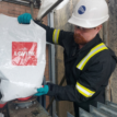
Thorne & Derrick provide Electrical Safety Equipment to substation engineers, cable jointers, overhead linesmen and utility workers with PPE and electrical safety equipment including insulating gloves, voltage detectors, insulating matting and portable earthing to ensure worker safety when carrying out maintenance on LV-HV switchgear, substations, cables and electrical equipment.
We protect substation engineers, asset managers, SAPS, cable jointers, overhead linesmen and utility workers with PPE and safety equipment: this includes insulating gloves, voltage detectors, insulating mattingand portable earthing to ensure worker safety when carrying out repair and maintenance on LV-HV switchgear, transformers, substations and turbines.
All our Cable Connection & Energisation Accessories including Medium & High Voltage joints, terminations, connectors and cleats are tested to the latest international standards and supporting ranges of professional cabling tools are stocked to reduce incident, accident and downtime to plant and people.
Uploaded By - Chris Dodds (Thorne & Derrick Sales & Marketing Manager)
Press Release: Thorne & Derrick and Lucy Zodion | 17.6.22
STREET LIGHTING CUT OUTS
Thorne & Derrick, a Specialist Distributor for Lucy Zodion the market-leading manufacturer of Street Lighting & ICP Connection Solutions, are delighted to announce that Scottish Power Energy Networks (SPEN) have awarded a 2-year tender to Lucy Zodion to supply the following G81 approved products:
Lucy 0260009009SLF 25A Street Lighting Cut Out TYPE 1 SNE Boxed
Lucy 03500120095 Way Connector Box
The Lucy Zodion range of street lighting cut-outs, controls, feeder pillars and isolators are specified and installed by ICP’s throughout the UK providing reliable and effective street lighting and electrical connections to our utility network.
Thorne & Derrick are Approved Vendors to SPEN and their Lloyds NERS accredited ICP’s, you can contact us for competitive prices and stock availability for the complete range of Lucy Zodion Street Lighting Equipment.
➡ For further information about how Lucy Zodion provide control and power distribution products for street lighting applications, please review the Lucy Titan (Cut-outs) and Lucy Trojan (Isolators) ranges of products.
Should you require any technical support or have any commercial requirements about G81 Approved 11kV/33kV Cables & Accessories please do not hesitate to contact Thorne & Derrick Sales Team.
Lucy Zodion SLF fused cut out
Separate neutral and earth (SNE) cut out
Maximum continuous load 25A
Simple cam lever fuse carrier removal
Single fuse
Double pole
Cut-out full conformity to BS7654
Terminals accept cables up to 25sqmm
IP22
2 x 20mmØ cable entry- grommets
Lucy Zodion Cut Outs | The SLF cut out range is approved by all Distribution Network Operators (DNO’s) throughout England, Scotland and Wales – G81 approved versions are available for ICP/IDNO connections.
Lucy Zodion Cut Outs
SPEN SAP Code*
Lucy Zodion Part Code
Description*
30980590
0260009009
CUT OUT 25A STREET LIGHTING TYPE 1 SNE: 25 AMP STREET LIGHTING CUT OUT, SNE CONSTRUCTION
SLF
Lucy Zodion MLNS – 5 Way connector block
MLNS
Maximum continuous load 100A
Suitable for phase, neutral or earth conductors
Serrated cable bores accept conductors up to 35mm² section
Two M8 slotted head cable pinching screws per conductor
Sealing wire facility
IP22
Removable shields for unused cable entries
Robust thermoplastic housing
SPEN SAP Code*
Lucy Zodion Part Code
Description*
30980639
0350012009
100 A, 5 WAY SINGLE POLE CONNECTOR BLOCK. SUITABLE FOR TERMINATING PHASE, NEUTRAL OR EARTH CONDUCTORS
*The SPEN part codes and descriptions in the tables are taken directly from the tender document.
Lucy Zodion’s SLCOs are compliant with BS7654, which covers all aspects of the cut out from the materials in which it is manufactured, to a series of tests relating to temperature, ingress protection, current and mechanical strength.
BS 7654 | 10th Edition, May 15, 2020 | Specification for single‑phase street lighting cut-out assemblies for low-voltage public electricity distribution systems – 25 A rating for highway power supplies and street furniture | purchase copy.
About SPEN
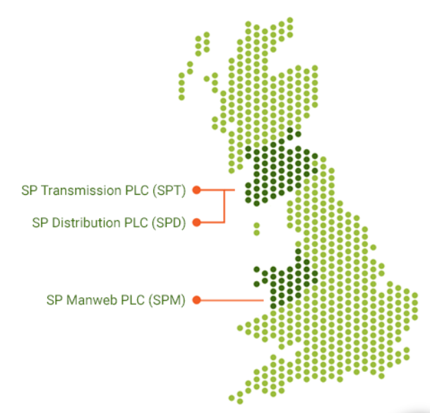
SP Energy Networks are a Distribution & Transmission Network Operator keeping electricity flowing to homes and businesses throughout Central and Southern Scotland, North Wales, Merseyside, Cheshire and North Shropshire – this is achieved via a network of Overhead Lines & Underground Cables which they own and maintain.
This includes over 30,000 substations, 40,000km overhead lines and 65,000kmunderground cables.
3 SPEN Regulated Electricity Businesses
SP Transmission PLC (SPT)
SP Distribution PLC (SPD)
SP Manweb PLC (SPM)
THORNE & DERRICK
T&D are Specialist Distributors to UK Distribution Network Operators (DNO’s), NERS Registered Service Providers, ICP’s and HV Jointing Contractors of an extensive range of LV, MV & HV Jointing, Earthing, Substation & Electrical Eqpt– this includes 11kV/33kV/66kV cable joints, terminations and connectors for both DNO and private network applications.
Contact our UK Power Team for competitive quotations, fast delivery from stock and technical support or training on all LV-HV products.
Special thanks to Tristan Jones Business Development Manager at Swalek High Voltage Services
for kind permission to share
Wind Farm Fault Emergency Call-Out
11kV | 33kV | 132kV
Swalek provide a comprehensive range of Solar & Wind Farm Maintenance Services including high voltage power cable installation, jointing, termination and testing.
Swalek cover design, consultancy, installation, testing and commissioning, energisation, operation and maintenance for electrical networks and cables up to 132kV.
Having built over 30 wind farms and operating and maintaining renewable energy assets across the UK, Swalek is well placed to provide high voltage electric power consultancy, operation and maintenance services including:
Wind Farm Maintenance Services
GWO Certified
High Voltage Turnkey Solutions
Installation
SAP Service
Fault Analysis & Management
Consultancy & HV Safety
Operation & Maintenance
Commissioning
A Recent Wind Farm Maintenance Project Application
Swalek’s wind farm maintenance division supported a customer yesterday with their off-supply issue at a wind farm in Scotland, near Falkirk. An engineer attended site to assess the problem and found that the site had lost communications. The engineer checked the Scottish Power Network and didn’t find any problems. It was assumed that there was a loss of supply.
An investigation was then carried out and it was found that there was no supply to site or to the transformer to Scottish Power. The engineer contacted Scottish Power Energy Networks and discovered their switch had tripped on fault which was feeding the wind farm transformer.
A visual inspection was carried out on the transformer which didn’t indicate any stress or irregularities. The decision was made by Scottish Power to attempt a re-energization. The network tripped again immediately on fault and the decision was made to carry out an intrusive investigation.
The engineer then carried out a detailed investigation and it was discovered that Transformer 1 had a failure. An 11kV insulation resistance test was carried out which proved a fault on the HV winding. Swalek High Voltage Services are now in the process of sourcing and installing a new 800kVA transformer to replace the faulty transformer and ensure the wind farm continues to generate.
Swalek carry out wind farm high voltage design, build, operation & maintenance services throughout the UK and across Europe. Swalek deliver operation, maintenance and turnkey HV Design & Build (Civil & Electrical) balance of plant solutions for wind farm projects.
Wind Farm High Voltage Services
Site Management / SAP Duties up to 132kV
Control & Operation /HV Safety HV Consultancy
Switchgear & Transformer Installation & Testing
Design and Network Analysis, Discrimination Studies
Earthing Design
HV Electrical System Design
HV Electrical Installation Primary Substation: Construction & Commissioning
Swalek High Voltage Services design, installation, construction, commissioning, energising, maintaining and operating high voltage electrical infrastructures on 11kV, 33kV and 132kV private networks.
High Voltage Cable Spiking – provide specialist engineering teams to carry out cable spiking on underground cables
Switchgear & Transformer Maintenance – support you with Switchgear and transformer maintenance throughout your network
Design & Earthing Studies – professional and competent specialists ensure your earthing system is appropriate for the installation
Transformer & Switchgear Installation – installations are carried out to the highest safety standards and by fully trained engineers
Find out more about the operation & maintenance options Swalek High Voltage Services can provide to support you with maintaining the security of your electricity supply to your wind farm’s high voltage private network.
Specialist Distributors of High Voltage Jointing & Electrical Safety Equipment
Thorne & Derrick Internationalare Specialist Suppliers to the UK and international Wind Industry of products to provide safe and reliable LV HV Electrical Cable Termination, Jointing, Installation & Power Systems up to 66kV.
We are based in North-East England, recognised as a key strategic location to service the offshore renewables energy market in the UK, from the North Sea to the Nordics – our Exports Division support international offshore wind power projects from USA to China.
Thorne & Derrick distribute the most extensive range of MV HV Medium & High Voltage Cable Joints, Terminations & Connectors from manufacturers including 3M, Prysmian, Nexans Euromold, Elastimold, Pfisterer CONNEX & SEANEX.
Compound Box Filling Compound end boxes rarely get attention — until one fails. Across ageing networks, replacement of compound-filled end boxes is becoming more frequent, particularly where original insulation systems have deteriorated and air insulation is not practical because...
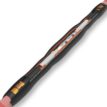
Nexans 240–300mm² Multi-Joint – Medium Voltage Cable Joint Installation Medium voltage cable jointing requires reliability, consistency and safe installation practices. The Nexans 240–300mm² Multi-Joint is designed to simplify medium voltage jointing while maintaining high electrical performance for demanding power...


 throughout England, Scotland and Wales - G81 approved versions for ICP?IDNO connections.")