

Blog
Cable Hooks | Reduce Slips, Trips & Falls from Trailing Cables
May 30th, 2025The Future of Cable Management – Trends & Innovations
-
uploaded by Chris Dodds (Thorne & Derrick) with accreditation to CableSafe.

In the engineering landscape, staying ahead of things is crucial, especially when it comes to cable management. At CableSafe, with operations spanning the Netherlands and the USA, we’re dedicated to pioneering innovative solutions in cable safety, confined space safety, and dropped objects prevention. Let’s delve into the future of cable management, examining emerging trends and exciting innovations shaping the industry.
Efficient cable organization is essential for optimizing workflows and minimizing hazards in industrial settings. Traditional methods often involve cumbersome cable trays and racks, but advancements in cable management solutions are simplifying the process. Products like CableSafe Safety Hooks Extreme and Cable Guards provide simple yet effective solutions for keeping cables organized and secure, reducing clutter and potential safety risks.
Elevated cable management solutions like CableSafe Cable Stands and Cable Bridge further streamline operations by minimizing tripping hazards and facilitating easier access for maintenance personnel. These innovations not only improve electrical safety but also contribute to overall efficiency on the job site.
As technology continues to advance, ensuring cable safety remains a top priority. CableSafe is dedicated to developing robust cable protection systems that mitigate risks and prevent accidents. Whether it’s through innovative cable guards or durable safety hooks, our products are designed to withstand the rigors of industrial environments while keeping workers safe.
Trailing Cable Safety
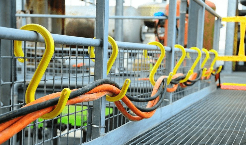
The Safety Hook Extreme is an advanced specification and high performance version of the standard industrial cable hook manufactured with glass reinforced PBT and is UV stabilized, Flame Retardant (Class: 94V-0, Flame Class Rating 3) and Cold Weather rated.

CableSafe Hooks
Looking ahead, the future of cable safety lies in proactive prevention measures and advanced monitoring technologies. By investing in smart solutions that detect potential hazards before they escalate, companies can minimize downtime and maximize productivity while safeguarding their workforce.
Every industry has its own unique challenges when it comes to cable management. From offshore oil rigs, wind turbines and to manufacturing facilities, CableSafe understands the importance of tailored solutions for elevating trailing cables. Our customizable products are designed to meet the specific needs of diverse industries, from corrosion-resistant materials for marine applications to fire-retardant coatings for high-risk environments.
As we look to the future, CableSafe remains committed to driving innovation and excellence in temporary, permanent and trailing cable management. By embracing emerging trends and leveraging cutting-edge technologies, we’re shaping the industry for the better. With our customizable solutions and unwavering dedication to safety, we’re empowering companies to create safer, more efficient workplaces for their employees.
Should you require any further information about improving Electrical & Cable Safety in your workplace, contact Thorne & Derrick.
Further Reading
- Thorne & Derrick Appointed Preferred Supplier of CableSafe Safety Hooks
- Cable Safety Hooks from Cablesafe vs. Traditional Cable Management
- Confined Space Entry Protection by CableSafe®
Ellis Patents Cable Cleats for Major Power Plant Project
May 27th, 2025
21.5.2025
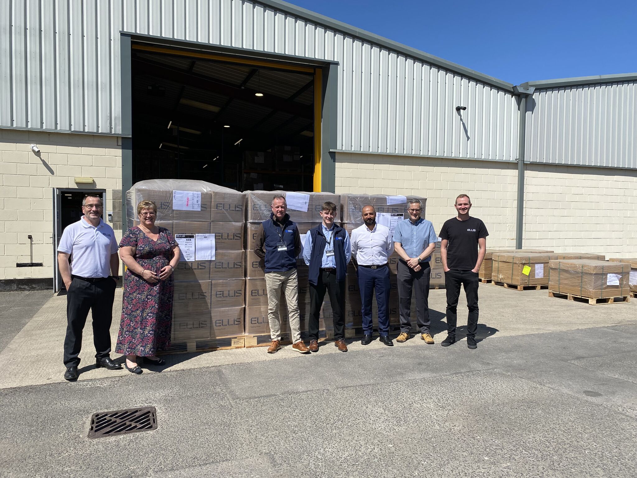
HOLDING POWER by Ellis Patents | 30,000+ Vulcan Cleats and Flexistraps shipped out today under the blazing Yorkshire sun. The cable cleats will provide short-circuit restraint to both 11kV and 33kV Medium Voltage Cable Networks.
This WIN demonstrates the high-value of collaborative, proactive and strategized Manufacturer-Distributor relationships; we look forward to co-creating a Case Study to highlight how together we have worked to secure this achievement and satisfy clients specification and technical application requirements.
The consignment is now to be delivered to SEB International Ltd, the UK’s leading manufacturer of Cable Pulling & Laying Equipment, and consolidated for shipment with a CD500S Cable Drum Trailer (Payload 20,000kgs | Max Drum Width 2400mm), TW5000 Cable Pulling Winch and CP700 Cable Pushing Unit to power-up an accelerated cable laying process.
The £750K project value to Thorne & Derrick demonstrates our ability to manage and deliver upon UK and international major projects from our robust world-class supply-chain.
The High Voltage 132kV Cables will be connected to Grid using GIS Dry-Type Terminations from Nexans while all Medium Voltage 33/11kV switchgear and transformer Connectors are completed using market-leading Euromold and Connex brands from Nexans Power Accessories and Pfisterer.
All Cleats & Cable Accessories supplied by Thorne & Derrick – the purchase contract was managed by Gary Amos (Thorne & Derrick Sales Engineer).
Ellis Patents | HOLDING POWER
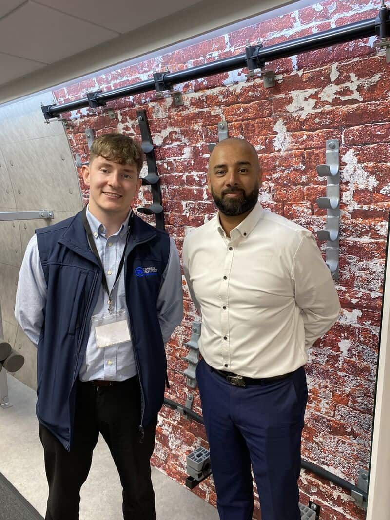
Pictured | Carl Cox (Thorne & Derrick Sales Engineer | Rail) with Noman Shabir (Ellis Patents National Sales Manager). The Ellis Patents ranges of PADS Approved Cable Cleats & Tunnel Hangers provide advanced material performance for substation, trackside and tunnel applications; this includes the short-circuit restraint and support of LV MV HV power cables. Please do not hesitate to contact Thorne & Derrick should you require further info, Lunch n Learn, CPD or Joint Visit to discuss your next cable cleat project requirements.

Ellis Patents Emperor Cable Cleats | Single & Trefoil | cable cleats designed, developed, tested and manufactured by Ellis from the Emperor range in accordance with IEC 61914 suitable for single, trefoil and Quad cable configurations
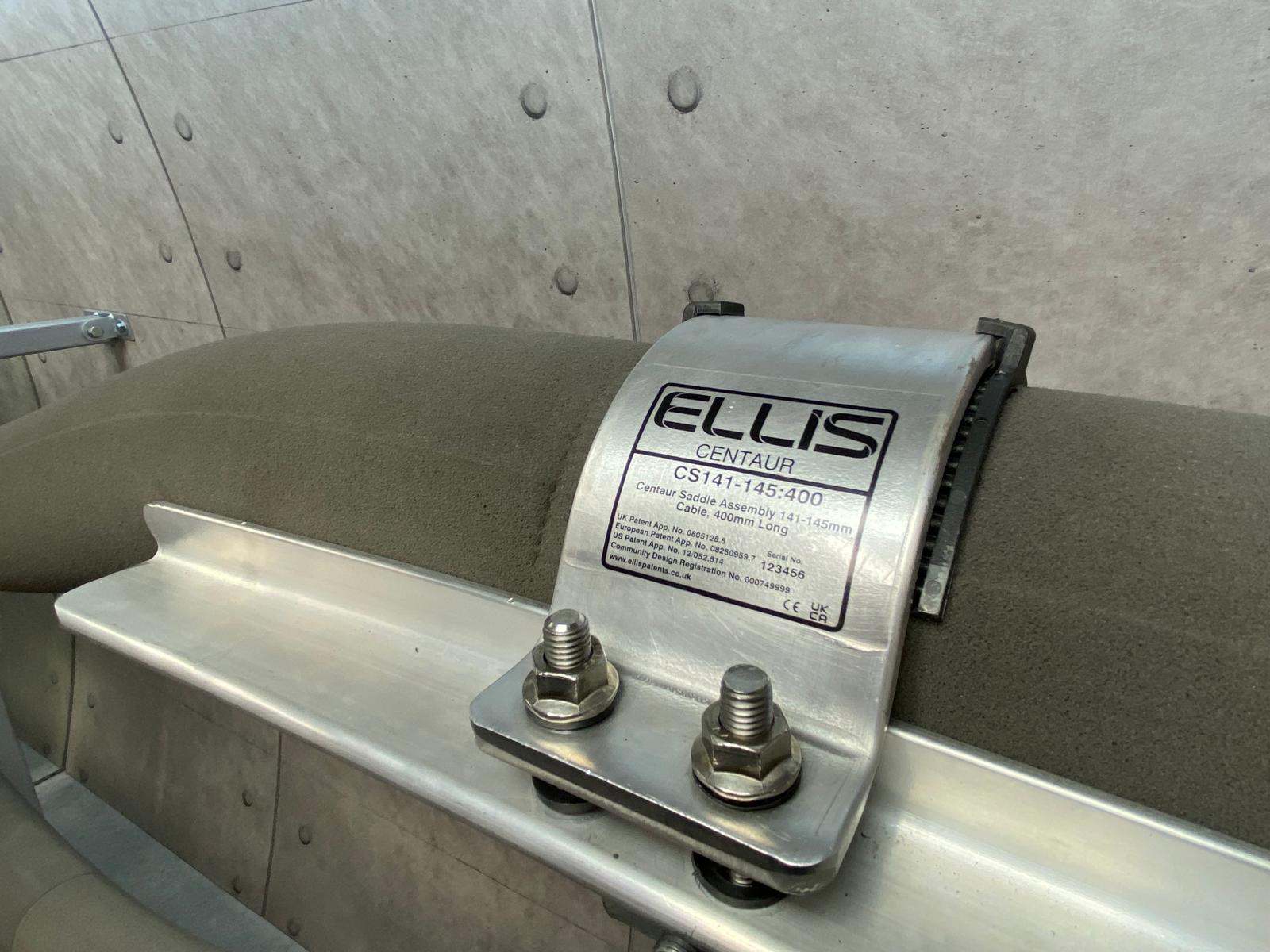
Ellis Patents Centaur Cable Saddles | the Ellis Centaur cable cleat has been designed, developed, tested and manufactured in accordance with IEC 61914 (Cable Cleats for Electrical Installations). The cable saddles are designed to support High Voltage Power Cables with diameters from 100mm to 162mm. Centaur consists of an extruded and pressed aluminium saddle and a hinged aluminium over strap.
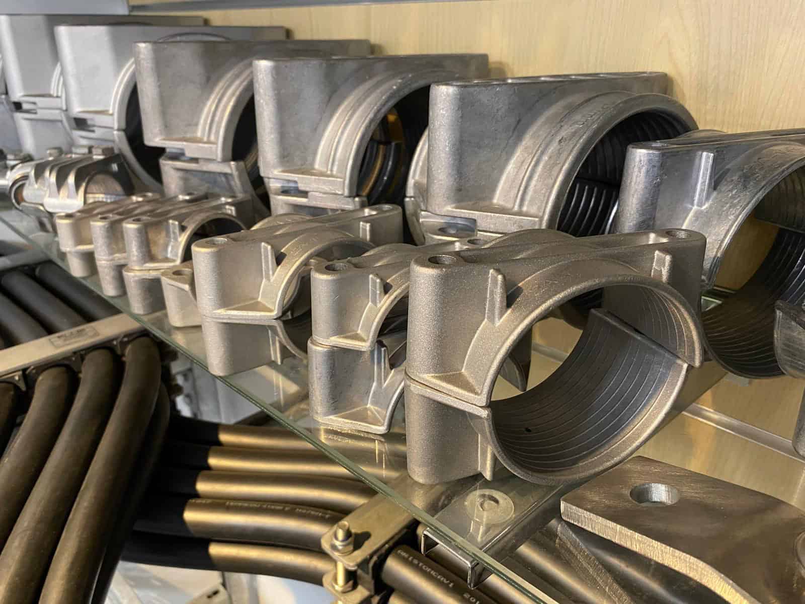
Ellis Patents Aluminium Cable Cleats | the Ellis 2A two hole cable clamps have been designed, developed, tested and manufactured in accordance with IEC 61914 (Cable Cleats for Electrical Installations). The cable clamps are available in a range of sizes with range taking ability to suit single cables – the clamp can be epoxy coated for use in harsh environments, such as sea air conditions.
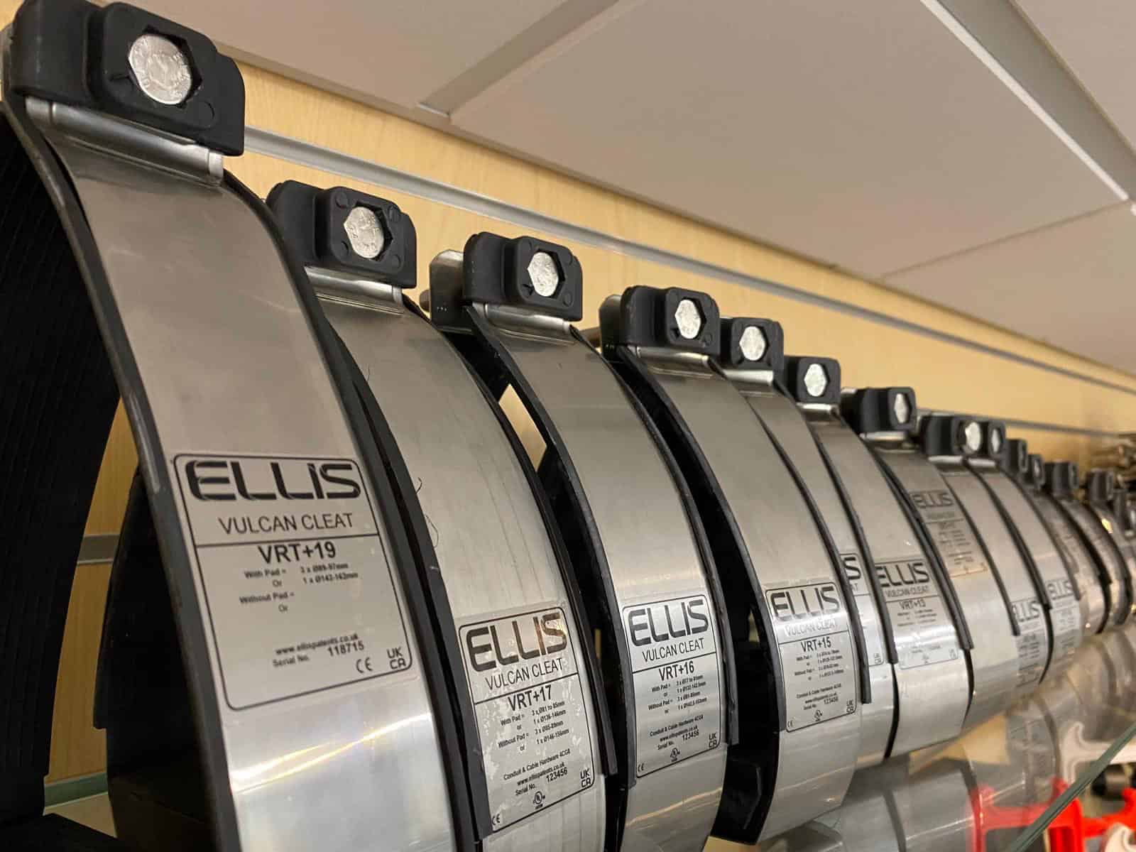
Ellis Patents Vulcan Cable Cleats | the Vulcan cleats are available in a range of sizes with range taking ability to suit single and trefoil cable formations (also available in Quad formation). The frame of the cleat is manufactured from corrosion-resistant 316L grade stainless steel, the cable is supported by a liner manufactured from a low smoke zero halogen (LSOH) material.
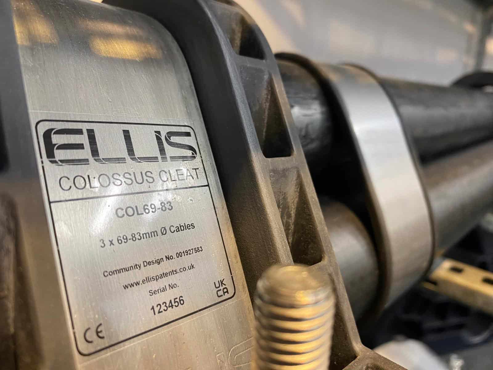
Ellis Patents Colossus Cable Cleats | The Colossus cleat is available in a range of sizes with range taking ability to suit LV MV HV cables in trefoil formation. The frame of the cleat is manufactured from grade 316L stainless steel, and the body of the cable cleat is manufactured from a low smoke and zero halogen (LSOH) material.
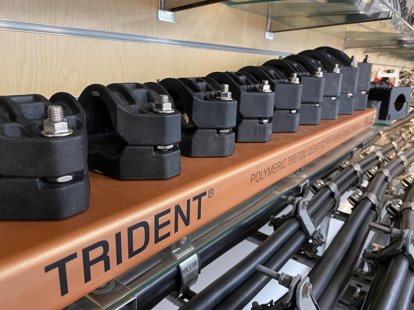
Ellis Patents Trident Cable Cleats | cable cleat is available in a range of sizes with range taking ability to suit LV MV HV cables in trefoil formation. The cleat is manufactured as standard in LSF which is PFAS and halogen free, flame retardant and suitable for outdoor applications.
Further Reading
- Ellis Patents Extend Vulcan+ Cable Cleat Range To Accommodate Smaller Cables
- Polymer Cable Cleats | Holding Power with Ellis Patents
- Cable Cleats | A Device For Short Circuit Protection | CPD Course By Ellis Patents
Cold Shrink Glands for MV HV Cables
May 21st, 2025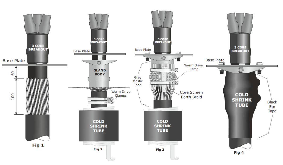
How to Install SPS 180 & SPS 193 Cold Shrink Cable Glands
To suit 3 Core SWA Armoured XLPE Cables, 3.6kV (3.3kV) to 36kV (33kV)
Reference Numbers: SPS 180(CS) and SPS 193(CS)
In this Post, we present a step-by-step installation guide for the SPS 180(CS) and SPS 193(CS) Cold Shrink ‘Bolt-On’ Type Cable Glands. These “top-hat” glands are designed to connect and gland 3-core armoured XLPE cables from 3.6kV to 36kV, providing a reliable and easy-to-install solution for Cold Shrink termination and are distributed by Thorne & Derrick.
Note:- Fig 1 shows one possible cable gland configuration, in some situations it may be necessary to position the 3 leg heat shrink boot body below the gland plate to gain space within the cable box. If cable is non armoured, additional strain may be put on the heat shrink tube to ensure cable is supported by cable cleats to provide additional strain relief.
Step-by-Step Installation Guide
1. Cable Preparation
-
Before opening up the armour wires, ensure the cold shrink tubes and the two worm drive clamps are in position.
2. Armour Wires
-
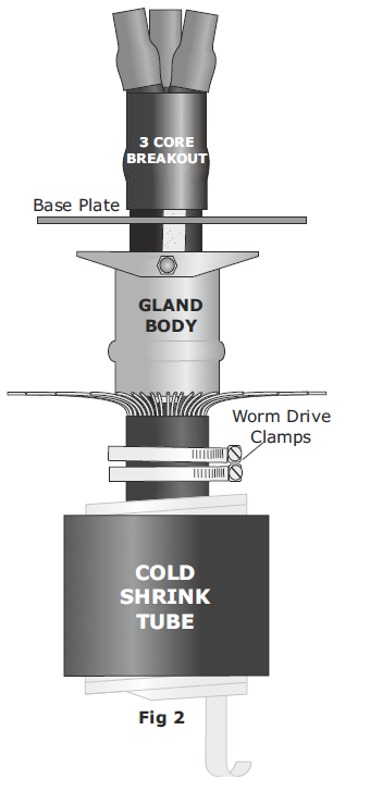
Open up the wire armours as shown in Fig 2.
3. Cable Gland Body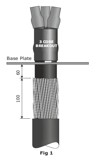
-
Slide the metal cable gland body over the cable.
Note: The cable gland body itself can, in most cases, be positioned after completing the cable termination.
For Steel Tape Armoured Cable:
Prepare to the same dimensions shown in Fig 1 and follow section 7 (see below).Configuration Tip:
Fig 1 shows one possible configuration. In some cases, you may need to position the 3-leg boot body below the gland plate to gain space within the cable box.Non-Armoured Cable Warning:
Additional strain may be placed on the shrink tube. Ensure the cable is supported by cable cleats to provide strain relief.
4. Final Connections
-
Complete the final connections of the cable termination before bolting the cable gland body in place.
5. Bend Armour Back
-
Bend the armours back over the cable gland body.
6. Clamping
-
Using the worm drive clamps, connect the cable armours and screen earth braids to the cable gland body as shown in Fig 3. Ensure the cable clamps are tight.
7. Cover Edges
-
Cover any sharp edges and the clamp buckles with PVC tape.
If Steel Tape Armoured:
Unwind the electrical tape below the bottom of the cable gland, re-wrap around the cable gland body, and secure with worm drive clamps.
8. Moisture Seal
-
To provide a moisture seal, stretch and apply a turn of grey mastic tape around:
-
The top of the metal cable gland body.
-
The outer cable jacket.
-
This ensures that the cold shrink tube will recover properly onto the tape.
9. Apply Cold Shrink
-
Position the cold shrink tube.
-
Begin pulling the plastic spiral carefully.
-
Do not pull the spiral straight.
-
Wrap it around the cable to avoid snagging.
-
10. Secure Ends
-
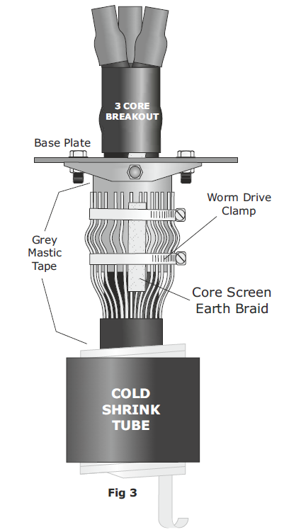
Once fitted, apply the provided black EPR tape at both the top and bottom of the tube.
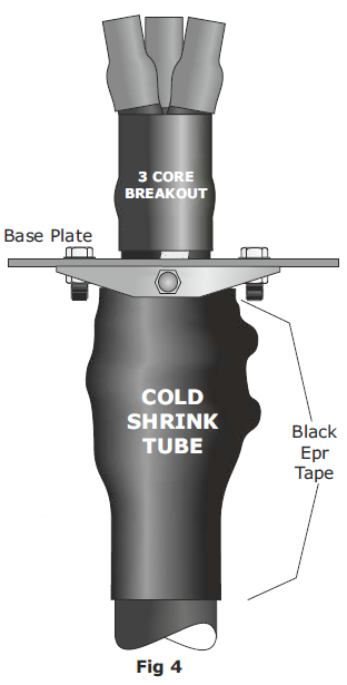
Figures for Reference
-
Fig 1: Base plate and initial configuration
-
Fig 2: Wire armour open-up
-
Fig 3: Clamp setup with screen earth braid
-
Fig 4: Final assembly with cold shrink and sealing tapes
Cable Glands Distributed from Stock by Thorne & Derrick | the 501/453 range of Universal Cable Glands manufactured by Hawke are suitable for the mechanical retention, glanding and termination of LV MV HV Power Cables with steel wire armour, steel wire braid or steel tape armour.


Shrink Polymer Systems heatshrink cable joints and terminations suit all types of MV-HV electrical cables (single or multi-core) with or without armour or lead sheaths – zero halogen and fire resistant cable joints are also available.
Duct Sealing Solutions with Filoform
May 20th, 2025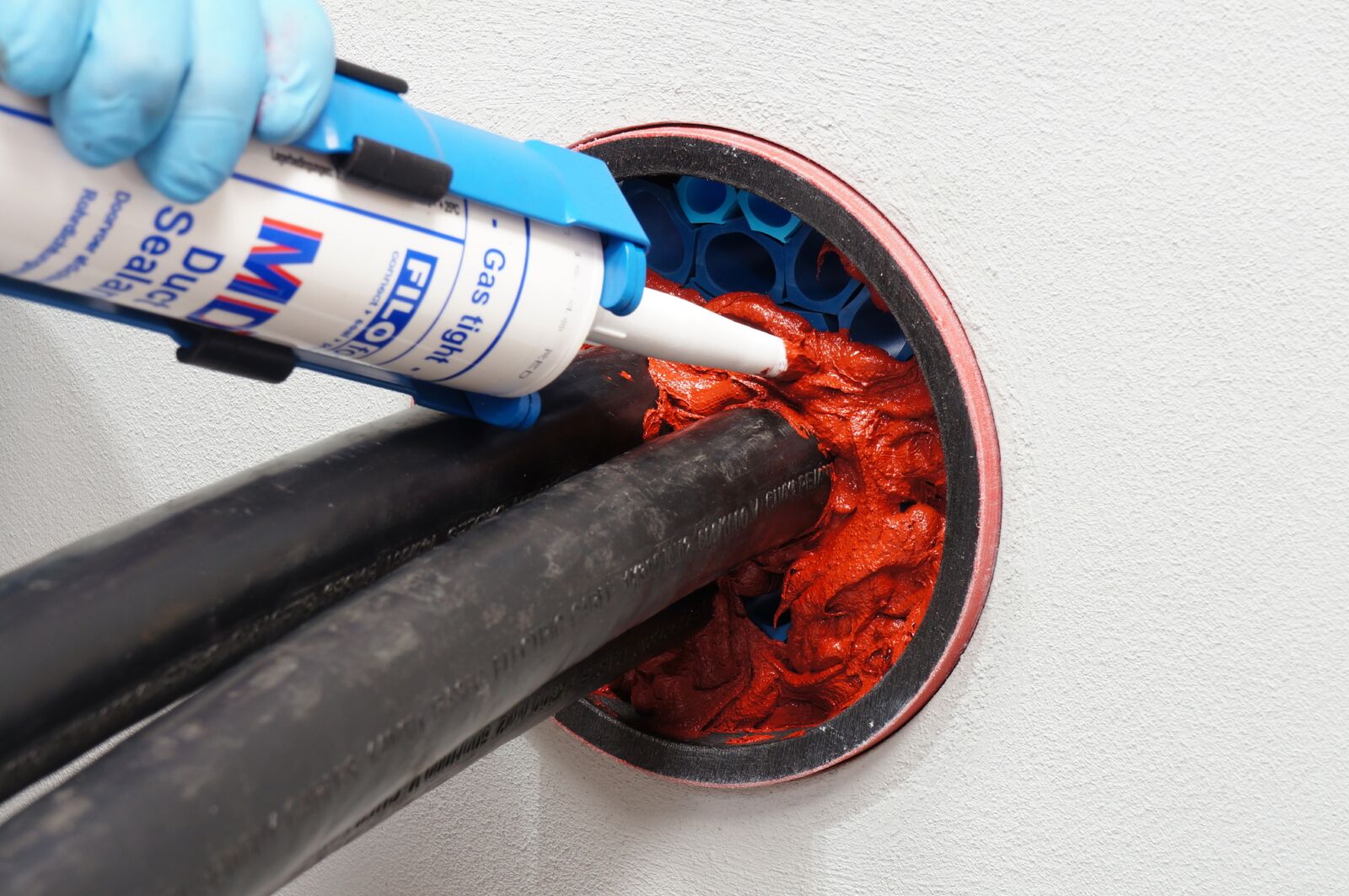
How Do I Select a Duct Sealing Solution?
 At Thorne & Derrick, we pride ourselves on working with industry leaders to deliver innovative, reliable, and compliant solutions to our customers. In this edition of Ask the Experts, Ian Joynson, Technical Specialist at Filoform, talks all things duct sealing — from common challenges in the field to the importance of long-term protection.
Filoform’s Ian Joynson shares expert guidance on what to consider when selecting the right duct sealing solution:
“Selection should start by understanding the specific application and what the seal needs to achieve. Consider:
➖ Are there cables present, and how many?
➖ Is water ingress an issue? If so, how much?
➖ Is fire protection required?
➖ Does the duct enter a building?
➖ Are gases or chemicals a concern?
The right solution should be chosen during the design phase, where sealing requirements can be aligned with the overall project scope.
Most specifications will demand resistance to water, gas, and sometimes fire or chemicals. Expected seal life is also critical — and any reputable manufacturer should be able to validate this.
Avoid over-engineering the seal design. Ultimately, a duct sealing solution that meets the specific needs of the application is the right solution.”
Thorne & Derrick is trusted distributor of Filoform duct sealing systems, supplying reliable and high-performance solutions to contractors, engineers, and project teams across the UK and internationally. Whether you’re sealing cable ducts in substations, renewable energy sites, or industrial facilities, we provide expert support and fast delivery to help you get the job done right.

Duct sealing and sealing products manufactured by Filoform, including the Filoseal range, are installed to provide gas tight and watertight sealing for cable duct entries – protecting underground cables and substation ducting infrastructure against flood and migration of flammable and toxic gas hazards. Fire resistant version also available – suitable for sealing LV-HV power, telecoms and fibre optic cables.
Filoform manufacture and supply quality products and solutions to connect, seal and protect low, medium and high voltage underground cable networks.

Thorne & Derrick provide competitive prices and fast delivery from stock for the complete range of Filoform duct seals and cable joints.
View the complete range of Filoform products.

FiloSeal+HD Duct Sealing System
From Power to Pavement: Enabling Smarter EV Feeder Pillar Solutions with Lucy Zodion
May 20th, 2025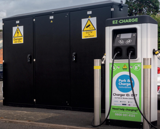
- Special thanks to Matt Page EV Business Development Manager at Lucy Zodion for the kind permission to republish.
BEYOND SPEED: FUTURE PROOFING EV INFRASTRUCTURE
As a trusted distributor of Lucy Zodion EV Feeder Pillars, Thorne & Derrick are proud to support the delivery of safe, robust, and future-ready power distribution solutions for electric vehicle charging networks.
In the article below featured in EV & Renewables Supplement, Matt Page, EV expert at Lucy Zodion, explores the critical factors beyond deployment speed that define a successful EV infrastructure rollout.
Lucy Zodion manufacture a wide range of products suitable to provide Low Voltage Electrical Power Distribution for EV charge points – from distribution network operator (DNO) accredited cut-outs and isolators for on-street chargers, to feeder pillars for electrical vehicle charging.
Lucy Zodion’s EVIS (Electric Vehicle Infrastructure Solutions) range delivers pre-wired EV feeder pillars from 100A to 630A reducing time on site and streamlining installation.
Beyond Speed: How to Future-Proof Your Infrastructure
Discover how strategic planning, scalability, and long-term resilience are key to building a charging network that’s ready for tomorrow.
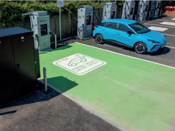
Conversations around EV infrastructure often focus on speed – how quickly can a charging station be deployed, and how fast it can charge a vehicle. While speed is important, it’s not the only factor that determines success. True future-proofing means designing charging infrastructure that is resilient, scalable and adaptable to changing demands and evolving technology.
Building for growth, not just now
Many charging hubs installed today will need to evolve as EV adoption increases. The latest figures from Zapmap show there are now over 75,000 public charge points in the UK our demand is expected to grow significantly and infrastructure that isn’t designed with scalability in mind will quickly become obsolete.
For example, at InstaVolt’s Camphill Village Trust charging site, the approach to power distribution was designed with long-term scalability in mind. The specialised our Main Supply Pillars powering the site’s 160kW chargers were built to support future expansion while maintaining a minimal footprint. Taking this kind of forward-looking approach can prevent costly redesign later on
Similarly, the Isle of Man’s phased EV rollout demonstrates how strategic planning can ensure charging infrastructure is deployed with future expansion in mind. A well-planned approach to power distribution means sites can scale up as EV adoption increases without requiring extensive retrofits.
Resilience is key
Reliability is just as critical as speed. A charging hub that experiences frequent outages due to inadequate electrical protection or environmental wear will create frustration for drivers and site owners alike. Key resilience-focused features to consider include:
- Earth leakage protection and residual current protection to ensure long-term electrical safety
- Surge protection to guard against power fluctuations
- Anti-condensation heaters and service lighting to protect internal components and improve maintenance access.
Integrating these features from the outset can help prevent operational disruptions, enhancing user confidence and reducing long-term costs.
The M7 Real Estate project delivered by Source EV – a joint venture between SSE Energy Solutions and Total Energy – highlights the benefits of durable, weather-resistant power distribution. In high-usage environments, ensuring electrical protection and ease or maintenance is crucial for long-term success.
Collaboration matters
Future-proofing isn’t just about the technology – it’s about the process. The most effective EV infrastructure projects take a holistic, end-to-end approach, Considering electrical distribution, space constraints and future adaptability from the start.
A strong example of this is the InstaVolt project, where power distribution was designed to allow flexibility for future transformer manufacturers equipment. Taking a collaborative approach with stakeholders ensures infrastructure remains adaptable to evolving industry requirements.
The road ahead
The shift to electric mobility is accelerating and infrastructure needs to keep up – not just with speed, but with smart, future-proofed design. Viewing EV infrastructure as an evolving system rather than a one-off installation can help ensure today’s investments continue to deliver value well into the future.
Incorporating scalable electrical systems, built-in resilience and cross-industry collaboration from the outset can help create charging networks that remain effective as demand and technology evolve. By planning with the long term in mind, we can ensure EV charging infrastructure stays ahead of demand, rather than struggling to catch up.
Compliance and standards
When specifying an EV feeder pillar, you need to make sure it is tested to the following standards:
- BS7671- IET Wiring Regulations – Covers the electrical installation of buildings, including the use of surge protection
- BS7671- IET Code of Practice for Electric Charging
- BS EN 61439 – Low Voltage Switchgear and Control Gear Assembly
Considering these key points will ensure that your EV feeder pillar is designed to deliver efficient and reliable power distribution for electric vehicle charging, contributing to a sustainable and greener future.

Lucy Zodion | Fortress Feeder Pillars | Pre-Wired Feeder Pillars | Street Lighting Cut-Outs | DNO Cut-Outs | Electrical Power Distribution Enclosures



