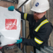
Enhancing Construction Site Safety with the CableSafe Adjustable Kick Plate
Construction site safety isn’t optional, it’s a legal and moral responsibility. With tools, materials and debris is constantly moving across elevated work zones, the risk of dropped objects poses a serious threat to workers below and to the overall success of any project. That’s why choosing effective safety solutions like the CableSafe Adjustable Kick Plate is essential for modern job sites.
Why Drop Prevention Matters on Construction Sites
Objects falling from heights are one of the most common causes of site injuries, equipment damage, and project delays. According to Occupational Safety and Health Administration (OSHA) guidelines, employers must provide protective measures such as toeboards to prevent falling tools and debris.
Dropped object prevention not only protects workers and assets it also helps companies stay compliant with safety standards. Traditional solutions often lack adaptability or durability and can be difficult to install or reuse across multiple projects.

Meet the CableSafe Adjustable Kick Plate
The CableSafe Adjustable Kick Plate is a smart safety solution designed specifically to address the vulnerabilities around platform edges and grated openings. Unlike fixed components, this kick plate offers flexibility and robustness which makes it ideal for a variety of elevated work environments.
Key Benefits:
-
Adjustable & Flexible: The kick plate can be extended to suit different opening sizes, helping you reduce engineering delays and custom fabrication.
-
Durable and Long-Lasting: Built from high-grade aluminium, it’s corrosion-resistant, recyclable, and ready for reuse across many projects.
-
Easy Installation: With a simple installation kit including galvanised J-bolts, spring pins and nuts, workers can set it up without hot work permits.
-
Standards-Compliant: Designed according to OSHA jump protection standards, this kick plate helps platforms meet safety thresholds for toeboard height and strength.
These features make the CableSafe Adjustable Kick Plate an ideal choice for contractors, site managers and safety professionals who are serious about dropped object protection.

Kick Plate Materials & Weatherability
- Strong aluminium frame (thickness 3mm – 012inch)
- Aluminium production is corrosion resistant, recyclable and is greener/environmentally friendly in comparison to plastic alternatives
- Silver coloured, but available in safety yellow for enhanced visibility of Adjustable Kick Plate barrier
- Excellent weather resistance and robustness
- Design in accordance with NEN-EN-ISO 14122
- OSHA approved design (Occupational Safety and Health Administration)
Kick Plate Features & Benefits
- Dropped Object Prevention
- Solid re-usable toeboard
- Lightweight and strong aluminium design
- Universal design for steel grated floors and walkway
Kick Plate Widespread Success
- Standard size universal design
- New design based on heavy industrial experience
- Used in many different applications
- Strong and simple in use
Where to Use Adjustable Kick Plates on Site
This solution excels around:
For permanent or temporary site edge protection, the adjustable kick plate easily integrates with other safety products.
CableSafe Adjustable Kick Plate Installation
The CableSafe Toeboard product is very simple to install and can be easily removed by hand to provide flexible and reusable installation. Available in a universal standard size, the product is design to protect any size opening, simply by increasing the number of Adjustable Kick Plate units to suit the desired size gap/opening. The Adjustable Kick Plates will reduce turnaround time for engineering and design, as well as installation time constructing the grated floors and railings.
- Installed with clamps on grated steel floors
- Supplied with galvanised J-Bolt, spring pin and nuts
- No necessity for welding or hot work
- Not hot work permit or scaffolding required
- Fast and easy to install by hand (no tools required)
Complementary Safety Products to Consider
To build a robust site safety system, combine the adjustable kick plate with these CableSafe solutions:
 Electrical Safety Equipment | CableSafe
Thorne & Derrick stock and supply the complete range of CableSafe Electrical Safety Equipment, including Dropped Object Prevention, such as the Walkway Mat, Guard Net & Safety Nets. CableSafe safety solutions are essential to ensure LV MV HV cable safety and a generally safe working environment in sectors such as, construction, renewable energy, data centres, rail, oil & gas and petrochemical industries.

What Are Cable Cleats?
Cable cleats are mechanical devices used to fix, support, clamp and retain electrical power cables along their routing. They are engineered to restrain cables during short-circuit electromagnetic events, preventing excessive movement that could damage systems or create hazards.
Unlike cable ties, cleats are designed and tested specifically for short-circuit forces they absorb significant mechanical load when needed.
Why Specification Matters
The purpose of specifying cable cleats correctly isn’t just neatness it’s about:
-
Safety under fault conditions
-
Regulatory compliance with standards like IEC 61914
-
Protection of expensive electrical assets
-
Reduced downtime and maintenance costs
Cleats play a role in systems ranging from LV installations in buildings to HV transmission cable routes through substations and tunnels.
Cable Cleat Standards: IEC 61914 & More
When specifying cleats, the first question should be: Does the cleat meet the relevant standards?
IEC 61914 is the international benchmark for cable cleats. It defines test requirements, mechanical properties, and classification methods that ensure a cleat can withstand predicted short-circuit forces.
In addition, installations may require compliance with regional or industry standards such as:
-
BS 7671 (IET Wiring Regulations)
-
Fire performance standards for safety systems
-
Rail and utility specifications
These demand specific cleat ratings and materials.
Key Specification Factors
Cable Diameter & Voltage Class
Choose cleats based on the actual outer diameter (OD) of the cable not just conductor size. Cleats must fit the exact OD for effective restraint.
Additionally, different voltage classes (LV, MV, HV) pose unique force profiles during faults higher voltage systems typically generate stronger electromagnetic forces, demanding more robust cleats.
Mechanical Ratings & Short-Circuit Forces
Cleat manufacturers provide kA ratings which indicate the peak prospective short-circuit current the cleat can withstand, usually defined over specific spacing conditions. Always ensure the cleat’s rating exceeds the system’s calculated fault level.

Cable Cleat Types & Their Uses
Cable cleats come in various designs depending on cable configuration, installation method, and performance needs:
Single Way Cleats
Best for individual power cable runs where standard support and restraint are required. Used across LV to HV systems.
Used to restrain and secure individual low, medium, or high voltage cables, these single way cleats are ideal for flat or spaced arrangements. Common in substations and control panels where single-core or multicore cables are installed.
Trefoil Cleats
Designed for three single-core cables laid in a trefoil (triangular) formation. Trefoil cleats are vital in power distribution systems to control magnetic forces during faults. They’re typically used in high-current circuits or where space is limited.
Quadrafoil Cleats
Specialised cleats used for four single-core cables laid in a quad formation. Common in high-power or parallel circuit applications. Quadrafoil Cable Cleats improve current balancing and electromagnetic performance.
Stackable & No-Bolt Cleats
Stackable cleats allow multiple cleats to be mounted vertically, maximising space in cable ladders or risers. Boltless cleats are fast and tool-free to install ideal for panel boards, data centres and confined space environments.
Fire Resistant Cable Cleats
Designed for applications where fire performance is critical. Fire resistant cleats are made from low smoke zero halogen materials or stainless steel to maintain cable support under extreme heat, flame, or fire exposure.
Typical uses:
triplex Cable Cleats
Triplex cables are three single-core cables twisted together, commonly used in 11kV to 33kV MV HV installations. Due to their spiral shape, standard cleats often can’t securely hold them. To solve this, Triplex cable cleats surrounds are applied to form a circular profile, allowing standard cleats to be fitted safely and effectively.
Material Selection: Strength, Corrosion & Environment
Material choice affects performance and lifespan:
-
Stainless Steel: Exceptional strength and corrosion resistance great for outdoors, marine, or industrial environments.
-
Aluminium: Lightweight with strong mechanical properties, suitable across LV to HV.
-
Polymer / Nylon: Cost-effective, light, fire and UV options available. Ideal for indoor and non-extreme environments.
Consider environmental exposure like chemical presence, temperature extremes, UV exposure and fire risk when selecting materials.
Installation & Spacing Best Practices
Correct installation technique and spacing directly affect performance:
General Steps
-
Position cleats at manufacturer-recommended intervals.
-
Align with cable diameter and configuration.
-
Secure cleat with correct fixings.
-
Tighten to keeper torque without damaging insulation.
Under-tightening risks slippage; over-tightening can distort cable jackets precise torque is crucial.
Spacing depends on cable size and fault current tighter spacing is often needed in high short-circuit scenarios.
Conclusion: Choosing the Right Cable Cleat
Correct specification of cable cleats is a blend of engineering, safety awareness, and standards compliance. By understanding cable layouts, force ratings, materials and installation practices, designers and installers can ensure safe, robust and code-compliant installations across LV, MV and HV applications.
When selecting a cable cleat, consider:
-
Cable Diameter – for proper sizing and fault force calculations of the electrical cable
-
Cable Voltage – LV, MV, or HV applications
-
Construction – armoured or unarmoured
-
Environmental Exposure – fire, corrosion, or chemical resistance
-
Containment Method – tray, ladder, or hanger
Cleats must be IEC 61914 compliant, tested to withstand peak fault forces.

Ellis Patents based in the UK are world leading manufacturers of cable cleats and cable clamps used to clamp and support LV-MV-HV cables – this includes cable support and management products to provide short circuit protection for 600V, 11kV-33kV-66kV and medium/high voltage power cables in single, trefoil or bundled formation up to 400kV.
Cable hangers support single or multiple cables – hangers and cable hooks are available in both galvanised steel and nylon and are used to support horizontal cable routes to building and tunnel structures. A complete range of steel cable hooks are also available compliant with 18th Edition of the IET Wiring Regulations (BS7671) is effective as of January 1, 2019.

Why Liners are Essential in Cable Cleats and Cable Straps: Protecting Cables, Performance, and Safety
When it comes to electrical power installations from LV distribution to MV/HV power networks the small details make a big difference. One element often overlooked by designers and installers is the liner in cable cleats and cable straps. Although seemingly minor, liners play a critical role in cable protection, system reliability, and regulatory compliance, particularly in high-fault environments, as highlighted by manufacturers such as Ellis Patents through extensive testing and field experience.
What is a Cable Cleat?
Cable Cleats are devices used to secure, fix, strap and support electrical power cables in an installation, ensuring safe operation and prevention of damage or injury, specifically in the event of a short circuit. Cable Cleats in Data Centres are ultimately purposed to increase/enhanced safety, organisation, cable protection, containment and ensure optimal performance. Typically, Cable Cleats are designed to be attached to various surfaces, such as ladders, trays, struts, rails, or beams.
What Are Cable Liners?
In the context of cable support hardware, liners are protective layers placed between the cable’s outer sheath and the rigid surface of a cleat or strap. They’re typically made from polymeric or elastomeric materials that cushion and protect the cable while still allowing the cleat to perform its fundamental role — holding cables securely in place.
Linings are engineered to be compatible with a wide range of cable types and environments and are often supplied with specific cleat models where the manufacturer has identified a need for additional protection through compliant or energy-absorbing materials.

The Critical Role of Liners
While cable cleats and straps are designed to secure cables against movement, especially during high-fault conditions, the interface between metal hardware and the cable sheath can be a point of vulnerability if liners are not used. Here’s why liners matter:
1. Prevent Sheath Damage and Ground Faults
Cables are engineered with a protective outer sheath that guards against moisture ingress, abrasion, and environmental stress. Direct contact between bare metal cleats or straps and this sheath particularly under the high forces generated during short circuit events can cause abrasion, deformation, or even cutting through the cable sheath. If the conductor or screen is compromised, a ground fault or insulation failure can occur risking safety and operational performance.
2. Cushion Against Mechanical Stress
During operation, cables undergo thermal expansion and contraction, vibration from mechanical systems, or dynamic loads during electrical faults. Liners act as a cushion that distributes mechanical pressure evenly, helping to absorb these stresses without weakening the cable jacket and maintaining the integrity of the installation over time.
3. Improve Reliability and Lifespan
Even without catastrophic damage, continuous friction, vibration, or contact pressure can cause small micro-abrasions to the cable sheath over time. This accelerates wear and shortens cable service life, leading to more frequent maintenance, replacement costs, and potential failure downtime. Proper liners help mitigate gradual degradation.
4. Support Regulatory and Standard Compliance
International standards such as IEC 61914 which governs the specification and testing of cable cleats emphasise mechanical protection and appropriate cable restraint for safety and compliance. Omitting liners where they’re called for in a specification can lead to non-compliance and additional risk for installers and certifiers, potentially affecting liability and acceptance.
When and Where Liners Are Most Important
Not every cable application requires liners, but they are especially critical in the following scenarios:
-
High-Voltage and Medium-Voltage Cables: Softer insulations or XLPE sheaths can be particularly vulnerable under short circuit forces.
-
Single-Core Power Cables: These often lack internal support, making the external sheath critical for mechanical protection.
-
Soft Sheath Materials: EPR, PVC, or elastomeric jackets can be more easily damaged by point loads.
-
Vibratory or Thermal Cycling Environments: Machinery, transit systems, or industrial settings where cables are subjected to movement or temperature swings.
Best Practices for Liners in Cleat and Strap Installations
To get the best out of liner-equipped support hardware, follow these practices:
Follow Manufacturer Guidance
If the cleat or strap design specifies a liner, always use it do not substitute or omit without consulting technical documentation.
Select the Right Liner Material
Polymeric liners (such as low smoke zero halogen types used in many MV/HV applications) provide not only mechanical protection but also help mitigate smoke and toxic emissions in fire scenarios.
Inspect During Installation
Ensure liners are properly seated and not displaced during tightening. Misaligned liners can cause point loading, defeating the protective intent.
Document Compliance
Keeping installation records that show liners were specified and correctly installed supports quality assurance and regulatory compliance critical on high-stakes power projects.
Small Component, Big Impact
Cables are the lifeblood of electrical power systems and even the most robust power infrastructure is only as reliable as the components that support it. Liners in cable cleats and straps may be small, but they play a critical role in cable protection, system reliability, and safety compliance.
By understanding why liners matter — and applying best practices during specification and installation engineers and installers help ensure safer, longer-lasting and more resilient electrical systems.
 Ellis patents
Ellis Patents based in the UK are world leading manufacturers of cable cleats and cable clamps used to clamp and support LV-MV-HV cables – this includes cable support and management products to provide short circuit protection for 600V, 11kV-33kV-66kV and medium/high voltage power cables in single, trefoil or bundled formation up to 400kV.

Insulating Matting Recommendations and Guidance for Electrical Safety
Guest Blog From COBA
Electrical safety is non-negotiable, especially when working around live switchgear, high-voltage panels, and electrical distribution equipment. One critical but sometimes overlooked safeguard is electrical insulating matting, designed to protect operatives from electric shock by insulating them from earth potential during live working.
Insulating matting is a essential component of electrical safety and is specified and installed to provide protection against electrical shock and hazards around electrical equipment, such as switchboards and switchgear – this can include Low Voltage, Medium Voltage & High Voltage.
What Is Electrical Insulating Matting?
Electrical insulating mats are specialist workplace safety products. They are made from dielectric elastomer rubber and placed in front of switchboards, control panels, generator housings, and other high-voltage equipment. Their purpose is simple but vital: to prevent people from becoming part of an electrical circuit that could deliver a shock.
COBA’s insulating matting, marketed as COBA Switch BS EN 61111, conforms to the internationally recognised BS EN 61111:2009 (aligned with IEC 61111:2009) standard. This standard ensures consistent quality, performance and safety characteristics for insulating mats used in live working.
Understanding BS EN 61111:2009 – Why It Matters
BS EN 61111:2009 is the current European adoption of the IEC 61111 standard for electrical insulating matting. It sets out:
- Classification by electrical performance: mats are grouped by dielectric strength and thickness, helping you match matting to expected working voltages
- Rigorous testing requirements: including dielectric withstand and proof tests to verify insulation performance
- Physical criteria: such as minimum dimensions, slip resistance, mechanical and environmental tests
- Marking and traceability: clear class and voltage rating identification for safe selection and audit compliance
This standard underpins every COBA Switch mat, giving end users the confidence that the product meets internationally accepted performance benchmarks.
How Electrical Insulating Matting Protects Workers
At its core, insulating matting provides a non-conductive barrier between a worker and the grounded floor. In high-voltage environments, if someone is standing on a conductive surface, they can become part of the electrical return path.
An insulating mat reduces that risk by increasing resistance to current flow, which lowers the likelihood of electric shock during live operations.
Practical benefits include:
- Enhanced operator safety when working near live equipment
- Dielectric protection matched to voltage class (see BS EN 61111 classification)
- Slip-resistant surfaces that improve workplace traction
- Resistance to oil, acid and low temperatures, increasing durability in industrial settings
Selecting the Right Mat: Classification and Voltage
BS EN 61111:2009 defines multiple classes of matting based on dielectric performance and typical working voltage ranges. This makes it straightforward to select a mat that aligns with your application’s requirements:
- Voltage capacity rises with class and thickness
- Colour coding on the mat’s underside makes identification quick and clear during installation and inspection
When specifying matting, choose a class with a working voltage rating equal to or greater than the highest voltage present in the area where the mat will be used. This ensures adequate protection and aligns with the standard’s guidance for safe live working.

Guidance on Inspection and Maintenance
Even the best electrical insulating mats need regular inspection and maintenance:
- Inspect mats visually before use check for cracks, tears or surface defects. Any damage can compromise insulation integrity.
- Replace mats immediately after an electrical incident, as the dielectric properties may be compromised.
- Annual electrical testing is recommended to confirm continued performance, particularly in environments with heavy foot traffic.
Proper care, storage (clean, dry locations) and adherence to inspection schedules help ensure the matting performs as intended throughout its service life.
Where Electrical Insulating Matting Should Be Used
Electrical insulating matting is suitable for:
- In front of switchboards and control panels
- Around transformer rooms
- In areas with high voltage equipment
- Generator houses and electrical distribution hubs
Its installation is a key part of establishing a safe working zone and reducing the risk of contact with energised parts during maintenance, testing, and live working.

Electrical Safety
Electrical safety is built on layers of protection and insulating matting plays an essential part in that system. By understanding BS EN 61111:2009, selecting the right class of matting and maintaining it properly, you can significantly reduce electrical risk for personnel exposed to live working conditions.
If you have any questions about choosing the correct COBA Switch insulating mat for your application or would like tailored recommendations, our team is always ready to help.

By Chris Dodds | Thorne & Derrick – Sales & Marketing Manager
NGED Network Jointing
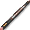
For contestable connections adoptable by NGED, Lovink Enertech 11kV and 33kV cable joints are specified, with the M-series LoviSil 33kV system being the Sole Approved Manufacturer for NGED adoptable 33kV joints within the Independent Connection Provider (ICP) sector – this covers 33kV Straight, Transition & Trifurcating Transitions applications according to G81 NGED Document.
Where cables undergo dynamic cyclical load in high harmonic and non-linear load applications the Lovink range of cable joints demonstrate years of fault-free field performance in high temperature installations. Additionally, the cable joints are “flame-free” and therefore safe for installation in potentially explosive atmospheres as no heating source or naked flame is required for the installation.
Lovisil has been approved for use by NGED for more than 25 years and is also widely used by UKPN providing a dielectric strength greater than 21kV/mm remaining fluid in service, allowing for natural movement without creating voids.

Private & Industrial Networks
Network resilience requires advanced technology solutions manufactured from highest performance materials; if high harmonics, Sine wave distortion, AD8 protection, abnormal thermal cycling, high-water table, ALE of legacy PILC or general cable failure prevention to critical 11/33kV circuit smatters to you, then talk to us.
NOTE:
If your network must overcome challenges such as:
-
High harmonics
-
Sine-wave distortion
-
AD8 water immersion requirements
-
Abnormal thermal cycling
-
High water tables
-
Asset Life Extension (ALE) of legacy PILC
-
Prevention of critical 11kV/33kV circuit failures
Lovink LoviSil liquid-silicone jointing technology is one of the most robust engineering solutions available for order.

LOVINK VISIT TO T&D
T&D recently hosted Lovink for a product training session focused on their latest medium-voltage jointing and connectivity solutions. The visit provided an opportunity for hands-on product demonstrations, technical discussions and knowledge sharing around installation best practices and applications.
It was a valuable session that strengthened collaboration and enhanced understanding of Lovink’s technologies and capabilities.
Thank you to Stephen Davies (Lovink Enertech Account Manager) for your emphatic presentation and roundtable with our incredible team.
trusted cable jointing technology
Lovink Enertech products are proven in service worldwide for network resilience, ease of installation, and long-term reliability.
Thorne & Derrick provide expert technical support, fast delivery and comprehensive stock availability for the complete Lovink range — from medium voltage straight joints to high voltage transition solutions.
Enquire Now
glossary
What does NGED mean?
The regional Distribution Network Operator (DNO) for the Midlands, South West and Wales responsible for the operation, maintenance and development of the electricity distribution network.
What does ICP mean?
Accredited companies permitted to carry out contestable works such as cable installation and jointing, allowing customers to connect to DNO networks.
What is a contestable connection?
Elements of new electricity connections that can be delivered by an ICP rather than the DNO, often including civil works and jointing up to the point of network adoption.
contact us
Thorne & Derrick support your Medium Voltage Jointing & Connection requirements.
Solar & BESS | Wind Energy | Data Centres | Rail | Hazardous Areas | Utilities
Speak with our MV Product Specialists today to discuss jointing, terminations and materials for your next project.