Earthing
January 4th, 2023

THORNE & DERRICK | EVENT SPONSORS
Due to the outstanding success of the 2022 Earthing Conference UK, IDC Technologies is excited to announce the return to Birmingham in 2023.
Thorne & Derrick are thrilled to be asked once again to be event sponsors!
Do you work in the electrical engineering domain, in the mining, industrial, power, defence, oil & gas, construction, transport, manufacturing, utilities, or renewable energies industry?
We are interested to hear from you.
The upcoming Earthing Conference UK in Birmingham on May 4th & 5th 2023 aim is to demystify the subject of earthing and present the subject in a clear, straightforward manner.
Earthing as a subject has been under-represented over the years and this event will attempt to remedy the gaps in technical knowledge and improve practices in the industry.
The UK & Europe need a unified practical approach to earthing which can be commonly understood and widely applied.
We are seeking a wide range of speakers to cover content outlined in our call for papers document, please click the link to review the extensive range of topics we wish to include into the 2023 conference program.

CALL FOR PAPERS
Speaking allocations are chosen on topic suitability, we welcome you to register your interest today by emailing [email protected] Once your topic is approved, your technical paper and PowerPoint slides will be due six weeks prior to the event.
Earthing Conference UK: Presented by IDC Technologies
Location: Park Regis Birmingham
Date: 4 & 5 May 2023
What Is Required From You?
- A 100-word abstract: an outline of the topic you would like to present. Please submit this electronically as soon as possible, to secure your place.
- Once your topic is approved, your technical paper and PowerPoint slides will be due six weeks prior to the event.
- Speaking slots are allocated on topic suitability and on a first come first served basis, so please register your interest today by emailing [email protected]
Enhance your career, share your knowledge and strengthen your public profile while networking with your industry.
Suggested topics:
EARTHING IN HIGH VOLTAGE INSTALLATIONS
• Earthing in Medium Voltage and Low Voltage installations and buildings
• Earthing, testing and measurements
• Portable earthing leads
• Protection for overhead lines, substations, underground cables
• Earthing systems for solar, wind, hydro
• Earthing systems for residential and commercial EV chargers
• Lightning protection and minimalization
• Innovative Solutions
• HV and LV earthing systems interconnection
• Data centre earthing considerations
• Earthing in Telecommunications and IT systems
• Surge protection practice
• Earthing modelling and software
• Sheath bonding methods, sheath voltage limiters
• Standards, best practices and innovative solutions
• UPS earthing systems
• Noise and harmonics effects & mitigation
POWER SYSTEMS
• System earthing
• Earthing of renewable energy systems
• Earthing of EV charging systems
• Equipment grounding & earthing of structures
• Electrical safety earthing
• Static earthing
• Solid, impedance, touch potentials
• Electric shock
• Earth leakage protection
• Design
• Protection
EARTHING
• Design and testing
• Earthing electrodes
• Measurement
• Neutral earthing
• Corrosion problems in earthing
• Earthing of surge protection devices
BONDING
• Sizing conductors
• Parasitic & stray currents
• Interference
• Hazardous areas
• Inspection procedures
• Equipotential grids
EARTHING, COMMS & INSTRUMENTATION
• Protection of instrumentation
• Instrumentation, radio & telemetry transmitters
• Telephone networks
• IT & wireless networks
• Mobile radio networks
• System bonding
TESTING
• Earth resistivity
• Earth loop impedance
• Grid resistance
• Earth continuity
INSTALLATIONS
• High voltage & low voltage
• Substations
• Augmentation of buried grids
• Geotechnical issues
• Hazardous areas
• Mining and oil & gas
• Marine and offshore
• Mobile plant
• Domestic electrical wiring
• Transmission, distribution & rail
LIGHTNING
• Protection design
• Non-conventional lightning systems
• Side flash and preventive measures
• Down conductor installation and termination
• Grid design
• Bonding
• Surge impedance
• Probabilistic risk factors
STANDARDS & REGULATIONS
• Standards and best practice
• State and utility regulations
• The need for new standards
• Inspection and testing
• BS 50522, BS 7430, BS 7354,
• BS 7671 – UK Wiring Regulations
• IEEE Std 80, ENA TS 41-24
SOFTWARE
• Load flow studies
• Fault load studies
• Equipment sizing
• Earth potential rise
UPS SYSTEMS
• Power quality
• Standby sources
• Solid state systems
• Redundancy
• UPS configurations
SURGE PROTECTION
• Bonding practice
• Surge protection practice
• Positioning and selection of lightning/surge arrestor
ELECTRICAL NOISE & MITIGATION
• Categories of noise
• Harmonics
• Frequency analysis
• Electrostatic/capacitive coupling`
All submissions welcome.
For further information on this event or to discuss sponsorship opportunities contact:
Vynka Malone
Conference Manager – IDC Technologies
[email protected]
IDC Events do not allow vendors to ‘sell’ their products in training sessions, instead the focus is on practical applications and solutions – which is, ultimately, the best way to showcase your technologies and engineering skills. In particular, we are seeking case studies, technical content, applications and the newest developments and research in this critical subject.
This event is an excellent opportunity to network with your industry peers, and to gain significant insights into earthing and related electrical safety practices, which are established, new and emerging.

Power Blog
Thorne & Derrick’s POWER Blog is regularly updated with news, projects, videos, technical tips, training information, promotions, webinars, career opportunities and white papers.
We focus on Product Categories: Duct Seals | Cable Cleats | Cable Glands | Electrical Safety | Arc Flash Protection | Cable Jointing Tools | Cable Pulling | Earthing | Feeder Pillars | Cable Joints LV | Joints & Terminations MV HV

January 3rd, 2023
– For more details download the event brochure HERE or register online HERE.
Introduction to Earthing
The aim of this Earthing Conference UK is to demystify the subject of earthing and present the subject in a clear, straightforward manner.
Earthing as a subject has been under-represented over the years and this event will attempt to remedy the gaps in technical knowledge and improve practices in the industry.
The UK & Europe need a unified practical approach to earthing which can be commonly understood and widely applied.
Few topics generate as much controversy and debate as that of earthing and the associated topics of bonding, grounding, surge protection, shielding, earth and lightning protection of electrical and electronic systems. Poor earthing practices can be the cause of continual and intermittent difficult-to-diagnose problems in a facility.
This conference will explore these issues from a fresh yet practical perspective, with the aim of helping delegates reduce expensive downtime in their plants and/or equipment. The conference will demystify the subject of earthing and present it in a clear, straightforward and – above all – practical and workable manner.
Earthing as a subject has been under-represented over the years; this event will attempt to close technical knowledge gaps and improve practices in the industry. The UK and Europe need a unified and pragmatic approach to earthing, one that is commonly understood and widely applied.
If you work in the electrical domain – in the industrial, power, defence, oil & gas, construction, transport, manufacturing, utilities, mining or renewable energy industries – then this conference is for you.
The 2023 conference builds on the outstanding success of the 2022 Earthing Conference, also held in Birmingham, which created a comprehensive and animated groundswell of discussion and learning.


What You Will Gain From Attending?
- To re-examine the application fundamentals for earthing, bonding, lightning, and surge protection.
- To discover best practice when earthing – to mitigate the impacts of faults and lightning strikes.
- To become familiar with the latest industry standards and procedures for earthing and lightning protection.
- To learn how optimal electrical earthing design can improve safety, production, and reduce costs.
- To gain practical advice on earthing system measurement.
- To receive design tips for earthing systems when conditions are challenging.
- To confront the pitfalls of inappropriate earthing and the hazards caused, and to discover how these can be prevented.
- To hear relevant local case studies from the UK electrical industry.
- To enjoy non-commercial presentations.
- To network with your peers and specialists in the field, and to discuss the issues raised.
Who Should Attend?
- Electrical engineers and technicians
- Substation, generation and transmission engineers
- Maintenance engineers and asset managers
- Engineering managers and electrical consultants
- Plant, project and design engineers
- Engineering and safety managers
- Lightning protection professionals
- Renewable energy specialists
- Government safety regulators/inspectors
- Network, protection and distribution engineers and technicians
- Maintenance specialists
- And all other electrical engineering professionals who have an interest in earthing
Your Keynote Speakers
Dr Jeremy Smallwood

|
Jayson Patrick

|
- Earthing and electrostatics consultant, trainer and researcher
- Expert advisor for BSI and IEC standards committees
- 2010 ESD Association Industry Pioneer Recognition Award for “advancing awareness of EOS/ESD throughout the world”
- Author of “The ESD Control Program Handbook” published by Wiley in 2020
|
- Technical Director at Electrotechnik, a company that develops leading electrical power system design and analysis software
- Master’s degree in electrical power engineering
- Electrical power system design and analysis expert
- Two decades of experience in professional software development for power system protection.
|
Day One | Thursday 4th May, 2023
Conference Program
8:00am Registration Opens
8:25am Welcome Address
8:30am Session One | International Keynote
Hands-On Workshop
Jayson Patrick: Technical Director, Electrotechnik
Accurately predicting earthing system performance, due to electrical fault currents, is necessary for ensuring a safe and economical design. This hands-on workshop involves software modelling of various typical earthing installation types including: a small (pad mount) substation, a large AIS substation, a GIS substation, a wind farm, and a solar farm to IEEE Std 2270 202. Actual field measurements will be analysed to devise an optimal soil resistivity model.
We will calculate touch, and step voltage limits in accordance with British and international safety standards. This workshop will focus on the applications of the software to typical challenges with earthing in a hands-on manner and is emphatically not intended to promote a particular brand or vendor. A software license will be sent to each delegate, input files, and notes to be used during the workshop shall be provided.
12:15pm Lunch
1:15pm Session Two | Case Study
Earthing System Modelling
Going Underground: Earthing of Tunnel Systems for HS2
Ross Falconer: Power System Studies Team Leader, Aurora Power Consulting
New train tunnels are being bored underneath London for HS2, the largest infrastructure project in Europe. During construction, the tunnel passages are supplied by HV cables to power tunnel boring machines (TBMs) and associated services. Safe earthing of the tunnel system is crucial to ensure personnel working underground are not exposed to dangerous voltages. This presentation will explore some of the practical challenges associated with earthing machinery which is moving over several kilometers, techniques for modelling underground earthing systems in earthing design software, how to apply BS 6164, and how earth potential rise varies as construction progresses along a tunnel.
2:00pm Session Three
Earthing Design and Safety
Sachin Dandare: Senior Design Project Manager, Electrical Design Services
Designing a proper substation earthing system is quite complicated and challenging; many parameters affect its design. In order to design a safe earthing system, it needs to provide a way to carry the electric currents into the earth under faulted conditions to limit the earth potential rise (EPR). This provides the assurance that a person and/or facility in the vicinity are not endangered. The earthing portion of a substation design will be explored in order to properly plan and design an earthing system. Background information and guidelines will be provided. A case study – including mitigation strategies will be presented to prove whether the design is safe.
2:45pm Afternoon Tea
3:15pm Session Four
Measuring the Resistivity of Crushed Rock in Existing HV Substations
Ken Atkinson & Jamie Forsyth: Senior Earthing Specialists, System Protection and Earthing Section, Network Assets, ESB Networks
This presentation will demonstrate an experimental method of directly measuring the resistivity of an in-situ layer of crushed rock in a HV substation using a portable generator, test leads, digital multi-meters and metallic foot probes. Interpretation of the results will include calculation of location-specific touch voltage safety limits which can then be
directly evaluated against measured touch voltages. The presentation will also include discussion of issues that were encountered during assembly of a prototype test meter and during field trials of the prototype, and suggestions for further work and research in this area.
4:15pm Session Five
Distribution Substation HV-LV Earthing Interconnection
Matthew Taylor: Managing Director, MJT Earthing and Lightning Consultants
Distribution (11kV/415V) transformers require both HV and LV earthing systems. These can be combined and connected to a single earth electrode or segregated; connected to separate HV and LV earth electrodes. There are pros and cons to both arrangements and the decision to combine or segregate should consider the transfer of HV earth potential rise onto the LV system. Guidance provided in the industry standards changed in 2012 but there is still some misunderstanding and confusion over the decision making process. Where segregation is required, standards and policy documents provide recommended separation distances between HV and LV electrodes to maintain safety. This paper presents the results of CDEGS simulations examining the impact of HV earth faults on typical LV networks in uniform and multilayer soils, to test whether the safety distances quoted are satisfactory.
5:00pm Day One Closing
Day Two | Friday 5th May, 2023
8:30am Session Six | Keynote Presentation
Earthing, Grounding and Bonding in Static Electricity and Electrostatic Discharge (ESD) Avoidance
Dr Jeremy Smallwood: Consultant, Electrostatic Solutions Ltd
Earthing (grounding) and bonding are widely used techniques in many technology and industry areas, but the practices used in electrostatic discharge (ESD) avoidance can seem rather unusual or difficult to understand. Using a minimum of theory, Dr Jeremy Smallwood explains the principles, and sometimes surprising similarities and differences in earthing and bonding practices from an ESD control view. He gives some simple examples of how an action or a change in circumstance that seems inconsequential, can lead to real problems or accidents.
10:15am Morning Tea
10:45am Session Seven
Earthing Applications for Lightning Protection
Sean Passant: Technical Manager, DEHN UK
This presentation will address the different approaches to touch and step potential in BSEN 62305 (Lightning Protection) suite of standards compared with the BSEN 50522 standard (Earthing of Power Installations). Using a sample project to show the three different earthing applications in BSEN 62305 and the relationship with assumed touch and step risks, it will be compared to the modellable risks using 3D software such as XGS lab.
11:30am Session Eight
The Importance of Earthing Processing Equipment Situated in Flammable and Combustible Atmospheres
Jonathan Rowe: Newson Gale Ltd
Earthing drains static charges away as they are produced, removing excess charge by transferring the electrostatic charge from the object to earth. This presentation will discuss case studies and analysis of incidents resulting from the ignition of flammable atmospheres due to discharges of static electricity. It will outline the importance of bonding metal dispensing and receiving containers together during transfer operations. It will look at novel ways of earthing multiple components at risk of electrostatic charge accumulation. It will correlate these measures with the guidance stipulated in IEC 60079-32-1: “Explosive atmospheres – Part 32-1: Electrostatic hazards – Guidance”.
12:15pm Lunch
1:15pm Session Nine
Rolling Sphere Analysis for Large and Complex Structures
Hugh Wren: Design Manager, Greymatters Global
While rolling sphere analysis has been applied for quite a number of years, it is often poorly understood and incorrectly applied. Many users fall into the common trap of trying to apply
a 3D analysis in 2D CAD, while others use tools that don’t reliably work for complex and large structures.
The presentation will show how 3D Rolling Sphere Analysis tools can be used to develop complex lightning protection systems with two main focusses – very tall structures, and structures with explosive atmospheres. The DSEAR regulations require that all risks of ignition, including lightning, must be addressed, and therefore designing an LPS that keeps lightning energy away from hazardous areas is critical.
2:30pm Session Ten
Earthing Design and Modelling Guide for Renewable Energy Projects
Jayson Patrick: Technical Director, Electrotechnik
Recently there has been an unprecedented number of generation projects as the UK targets 100 % renewable energy sources. A key component to the safety of these new facilities is the
properly designed earthing systems.
The combination of new technologies and the fact these projects cover large areas often over difficult and varying terrain presents challenges. The cost of these earthing systems can reach millions of dollars hence a small percentage of over-design will result in significant extra cost.
The same approaches for designing substation earthing systems cannot be applied to renewable projects. The modelling of the earthing systems will usually involve compromises, but accurate results are still achievable. This presentation will provide a guide to the earthing system modelling with references to relevant standards and real-world examples.
3:15pm Afternoon Tea
3:30pm Session Eleven | Panel Discussion
Panel discussion and Q&A with conference presenters. This is your opportunity to utilise a panel of conference speakers and industry experts to ask questions and find solutions to your specific earthing and grounding issues. Delegates are encouraged to participate in this invaluable and lively session.
4:30pm Conference Closing
4:30pm – 5:30pm Networking Drinks
An hour dedicated for all attendees to meet and socialise with experts and industry peers.
About the Keynote Speakers
Dr Jeremy SmallwoodDr Jeremy Smallwood is an earthing and electrostatics consultant, trainer and researcher with his company Electrostatic Solutions Ltd, providing services to industry since 1998. He works as an expert with BSI and IEC standards Committees.
He was awarded the 2010 ESD Association Industry Pioneer Award, 2017 International Fellow Award at Electrostatics 2017 and the Stig Lundquist Award at the Electrostatics 2022 conference. Jeremy has been publishing, attending and presenting papers for over 30 years in Journal of Electrostatics and at Electrostatics and the EOS/ESD Symposium conferences. He is author of “The ESD Control Program Handbook” published by Wiley in 2020.
Jayson Patrick
Jayson is the Technical Director at Electrotechnik, a company that develops leading electrical power system design and analysis software. Jayson has extensive experience working on large-scale power systems projects in high voltage design, testing/commissioning, and power system analysis roles along with two decades of experience in professional software development.
Jayson has a master’s degree in electrical power engineering, and he leads a multi-disciplinary team of developers, cloud architects, UI designers, electrical power engineers, and Ph.D. researchers. Jayson’s role at Electrotechnik involves developing new software and complex algorithms for electrical power systems design, where he is using a combination of technologies, multiple programming languages, and agile development practices.
General Information
Confirmation Details
A confirmation email and invoice will be sent to delegates within 3 days of receiving the registration.
Cancellation Policy
A 20% cancellation fee will apply for cancellations received 7 – 14 days prior to the start date of the conference. Cancellations received less than 7 days prior to the start date of the conference are not refundable, however substitutes are welcome.
Venue
Park Regis Birmingham
160 Broad Street, Five Ways, Birmingham B15 1DT, UK
Tel: +44 121 369 5555
Accommodation
The Park Regis Birmingham is offering all delegates 15% off the best bed & breakfast rate. Please book via their website and use the code ‘CORPORATE’.
Email: [email protected]
Telephone: +44 121 369 5555
Food and Beverages
All lunches, morning and afternoon refreshments are included in your delegate registration.
Unable to Attend
If you are unable to attend the full conference program, contact us for details to attend individual sessions or to purchase the Conference Resource Kit.
Register Now
www.events.idc-online.com
Phone: +44 (020) 8335 4014
Email: [email protected]
Sponsorship Opportunities
Representing your business at the Earthing UK Conference in 2023 will provide you the opportunity to reach key decision makers from a multitude of industries.
For more information on sponsorship and exhibition opportunities please contact: Vynka Malone at: [email protected]
Discounts
Early Bird Offer 10% Off
Book on or before 31st March 2023


POWER BLOG
Thorne & Derrick’s POWER Blog is regularly updated with news, projects, videos, technical tips, training information, promotions, webinars, career opportunities and white papers.
We focus on Product Categories: Duct Seals | Cable Cleats | Cable Glands | Electrical Safety | Arc Flash Protection | Cable Jointing Tools | Cable Pulling | Earthing | Feeder Pillars | Cable Joints LV | Joints & Terminations MV HV
November 15th, 2022

Earthing System Testing
In theory, earthing system testing is very simple, but in practice somewhat more complicated. Recently our development engineers Matthew Lee and Steven Preedy asked the question…Are we really testing R, Z or something else?
The authors have investigated and tested a range of scenarios and instruments and sought to be definitive. This article presents their methods, results, and conclusions.
In theory, earthing system testing is very simple. One simply applies a voltage between the system under test and a remote earth electrode, measure the current, measure the voltage ‘across’ the system under test, and divide it by the current.
In practice earthing system testing is somewhat more complicated. Questions often arise regarding the practicalities of testing, including:
- How do you establish a suitable remote earth?
- What type of voltage do you apply?
- How much current flow do you need?
- Where & how specifically do you measure the voltage?
- How do you measure both reliably?
- How do you detect and reject (or correct for) electrical noise, both AC & DC?
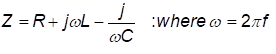
These are all important questions, and whilst many have reasonable answers, one question remains in dispute: If you test with an applied voltage that has both DC & AC characteristics, do you measure a resistance or an impedance?
The IEEE committee revising Std 81, amongst others, have wrestled with this question, and currently, there is no consensus. To answer the question “Are we really testing R, Z or something else?” the authors have investigated and tested a range of scenarios and instruments and sought to be definitive. This article presents their methods, results, and conclusions.

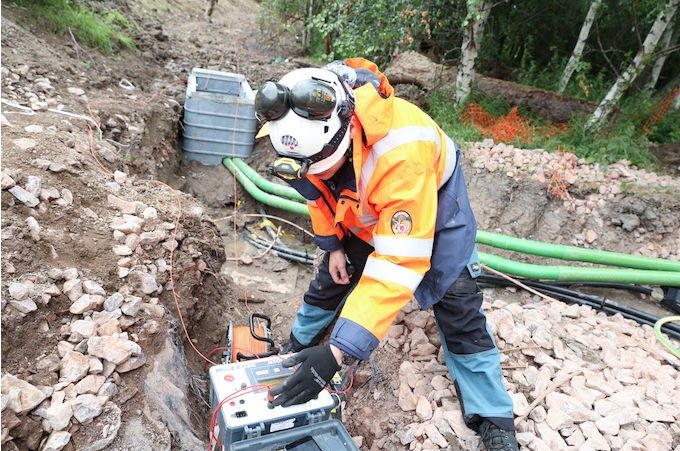
Safearth consultants in the field performing soil resistivity testing
Why are we asking this question and what are we testing?
For an earthing system to be effective, its performance needs to be adequate for the power system attached to it and all the factors that affect its performance need to be considered. The performance of the earthing system is entirely dependent of the ground in which it is placed.
The soil composition, existing infrastructure and mineral/moisture content all affect the apparent resistivity of the soil and thereby the performance of the earthing system. To assess the performance of an earthing system requires tests of parameters associated with or affecting that performance, including soil resistivity, EPR, resistance of earth grid, loop impedance, and continuity.
How Are We Testing?
To measure each of the aforementioned parameters current must be injected into the earthing system and/or the surrounding soil and the response measured. The injected current can be either a ‘Switched DC’ or an ‘AC current’ injection.
In both methods, the current is known, and voltage is measured. The question we are investigating here is “for a switched DC injection how should the measured voltage be interpreted?”
How do switched DC instruments work?
Switched DC instruments inject a known current in the form of a switched current square wave into the system. The voltage measurement is conducted at a specific part of the injected waveform, some in the middle and some at the end of the waveform.
Measurements are taken at these points to remove the effect of test lead coupling. With a known current and a measured voltage, ohms law can be applied – (R=V/I) to deduce the measured resistance.
What Happens When It Gets Complex?
Reactive elements in the system introduce complexity to an earthing system’s response. When measuring a complex system, the presence of reactive elements can affect the measured result. These reactive elements come from auxiliary paths such as overhead earth wires, buried conductors and cable screens.

Figure 1 Resistance Measurement of Complex Earthing System
How we showed the measurement can include errors
Using two switched DC instruments, we set up an equivalent circuit that would allow us to change real and reactive components. From this we could simulate how the measurement waveforms become distorted as the ratio of L to R increases and what the resistance tester records as the apparent resistance.
The setup was measured with zero inductance initially to establish a control value. All other measurements with inductance were compared to the control value.
What happens when we have reactive elements?
Based on one theory the behaviour of reactive elements is just …
The reality is that high inductance reacts to the injected switched DC current such that the resulting voltage waveforms become distorted, as shown in Fig 3. The distortion in the measured voltage waveforms create error within the measured resistance.
The result is that the magnitude of the measurement is larger than the resistive component of the circuit and is not indicative of the system under test. If the reactive element is small in relation to the real resistance, there exists a plateau near the falling edge of the received signal. This plateau is the real magnitude and contains little to no error being uninfluenced by the reactive element. By using the plateau of the signal, the measurement can be effectively used to calculate the real resistive element.

Figure 3 Measured voltage waveforms in high inductance circuits
How does impedance affect the results?
What we found was that the effects of inductance on measurement accuracy and reliability are dependent on the ratio of R to L, with the following features:
- Large R values negate low L values;
- Large L values dominate low R values;
- The L/R ratio does not imply the associated error;
- The error becomes significant when the millihenry range of inductance is reached; and
- The lower the frequency the more time for reactive elements to dissipate, allowing more time for a plateau to be reached.
Are we measuring an impedance with switched DC?
The short answer is no. Switched DC current injection measures the voltage at a certain point of the waveform and applies Ohm’s Law (R=V/I). It cannot measure a phase angle and thus cannot get a phase shift to deduce impedance.
The long answer is, it’s complicated. Due to the truncated measurement window technique used specifically by these testers, quantifying the amount of reactive information captured in that sample window is not trivial. In addition to this, the result is not a linear increase in error for a linear increase in inductance.
Does It Matter?
Typically, switched DC measuring instruments are reliable for individual electrodes, groups of electrodes and small to medium sized grids with no or minimal interconnecting paths. When testing on large grids or grids with multiple auxiliary paths, the effect of reactive elements can be observed by changing the injected frequency and noting that the recorded resistance changes with frequency.

Safearth engineers in the field performing soil resistivity testing
We ask again…. Are we really testing R, Z or something else?
These instruments are suitable for testing a resistance until they cross an implicit R/L ratio threshold. Past this threshold it appears that the inductive (L) component affects the measurement sufficiently such that substantial error can be observed. This measurement is relative to the circuit under test, but the reactive element cannot be deduced.
Through this investigation, it was found that 3 & 4 terminal switched-DC testers are always attempting to measure a resistance. When significant reactive elements are introduced into the circuit under test, the instrument ends up reading something else as it is trying to calculate resistance despite the measured waveform being distorted by the presence of the reactive elements. This implies that it is not an impedance being measured, the value that is calculated is only relevant to that specific circuit.
A way to check if there are reactive elements in the circuit is to change the frequency of the square wave. If the value doesn’t change, then it is dominantly resistive, and the measured estimate is valid. However, if the measured value changes significantly, there is enough of a reactive element in the circuit under test to affect the result and it must be considered an invalid measurement.
This article comes from the perspective of Safearth development engineers Matthew Lee and Steven Preedy who research, design, develop and manufacture our suite of Safearth earthing system test instruments. Their consultants regularly use our earthing testing equipment in the field in Australia and overseas. Original article can be found here – https://www.safearth.com/are-we-really-testing-r-z-or-something-else/
About Safearth

Safearth is a specialist electrical engineering group providing world-recognised expertise in safe power earthing systems.
Safearth delivers comprehensive earthing solutions and management to safeguard people and infrastructure from electrical faults and lightning. Since being established more than 30 years ago, we’ve designed and tested thousands of earthing systems for high voltage installations, for power utilities, mines, oil & gas sites, and other industries.

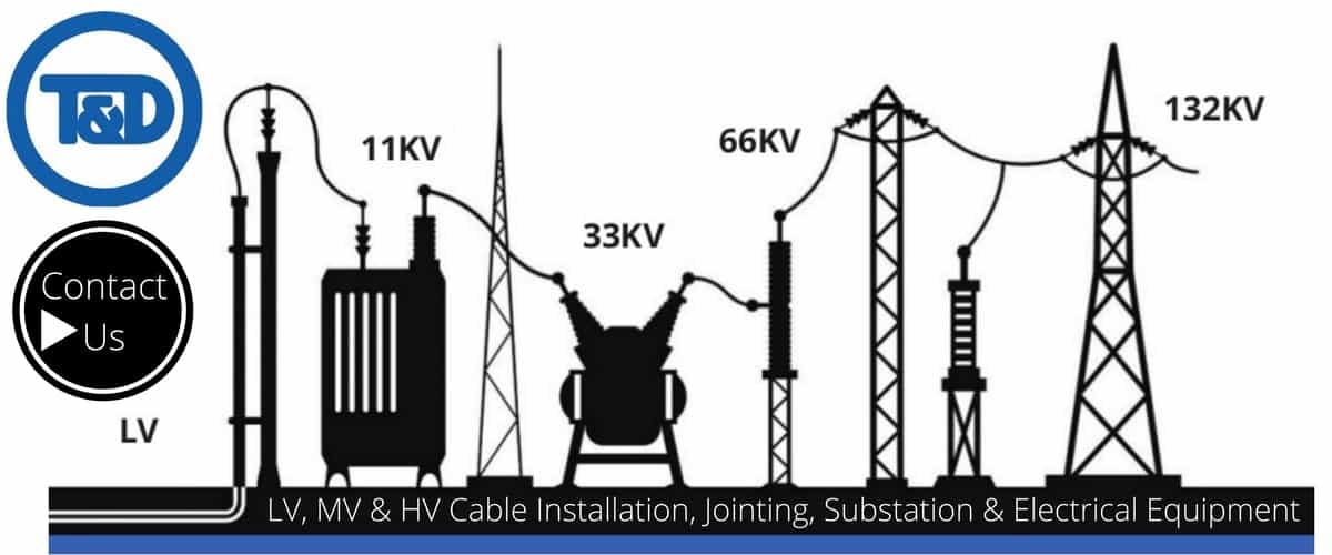
THORNE & DERRICK are national distributors of LV, MV & HV Cable Installation, Jointing, Duct Sealing, Substation & Electrical Equipment – we service UK and global businesses involved in cable installations, cable jointing, substation earthing, overhead line and electrical construction at LV, 11kV, 33kV and EHV.
Since 1985, T&D have established an international reputation based on SERVICE | INTEGRITY | TRUST.
Contact us for 3M Electrical, ABB, Alroc, AN Wallis, CATU Electrical, Cembre, Centriforce, CMP, CSD, Elastimold, Ellis Patents, Emtelle, Euromold, Filoform , Furse, Lucy Electric & Zodion, Nexans, Pfisterer, Polypipe, Prysmian, Roxtec, Sicame, WT Henley.
July 27th, 2022
Earthing & Lightning Protection | Earth Tapes | Earth Rods | Earth Tapes
Special Thanks To Ian Griffiths – Earthing System Design HV – Original Article Here
In this Guest Blog from Ian Griffiths (GreyMatters Principal Partner) we learn how what the difference is between grounding, earthing and bonding? That’s a question our readers and clients ask often.
Also, we’re asked quite a bit about earthing and bonding in general. So, there’s an unusually large amount of confusion around the term Earthing and Bonding. Or, for our friends in the states; you might come across the term grounding and bonding.
Therefore, in this piece, I aim to clarify the difference between – what is grounding, Earthing and what is bonding and whether there is a difference.
Breaking things down into simple terms; Earthing – grounding can mean all things to all people. Hence, it is more realistic to think of Earthing as the ‘electrode’ itself. Also, known as the Earth Termination. This reference refers to the physical hardware, such as the copper conductors, rods, etc., that sits buried directly in the geology itself.
Alternatively, Bonding on the other hand usually refers to the above-ground interconnections between the equipment or structures to be bonded.
What’s The Difference Between Earthing & Grounding?
There’s a lot of unnecessary confusion surrounding the difference between the discipline of Earthing and Grounding, which is kind of crazy, because, for the most part, the two are the same.
Earthing is the term used primarily by previous British colonies, whereas, Grounding is used more by those countries where the British had less influence.
So you might see the term Ground Potential Rise (GPR) or Earth Potential Rise (EPR) – both refer to the same thing! It’s purely a localism that has developed over time.
Difference Between Earthing & Bonding – Summary
So, to summarise Earthing and Bonding difference can be categorised as follows:
Earthing is the stuff ‘in’ the ground, and;
Bonding is the stuff ‘above’ ground.
Thus, knowing that some earthing system “stuff” is going to sit above ground level. And some will be below ground is a useful way of thinking about E&B (earthing and bonding). It’s also imperative to understand as part of an E&B design strategy that each item has a subtly different purpose.
Going The Extra Mile On Rail Networks
One thing is for sure, E&B is a safety-critical aspect on all HV networks, including Rail Network electrification schemes. And as part of GreyMatters mission to help save lives while making life as easy as possible to deal with us, you’d expect us to jump through some crazy-hard hoops in the process, right?
Sentinel
As a result, one such ‘hoop’ Sentinel. I have to confess, and it’s quite a significant commitment to making initially (November 2017) to become the only Earthing Consultancy on the planet to my knowledge to offer full Sentinel sponsor status for Network Rail E&B projects. This status means PTS certified engineers get trackside in the UK easily without any faff or hassle and full RISQS compliance comes built-in to keep the regulators happy on the governance side.
Not only that but we also made some eye-watering (for us) investment in high-energy testing equipment. Furthermore, the readings we take do not suffer from the common, yet not fully recognised rail-related external influences.
Often these sources of error usually cause no-end of uncertainty in a rail environment, i.e. lots of lovely conductive structures that run in parallel for miles. Incidentally, these are quite a headache as a source of interference, when testing using the conventional equipment. Again, this attention to detail is something that makes GreyMatters entirely different. As a result, it’s also something that other sectors can benefit from – not just rail.
Anyway, hopefully, this piece clears up the confusion regarding E&B (Earthing and Bonding) you might have held previously and given a small insight into E&B testing headaches on rail projects too.

ABOUT GREYMATTERS
GreyMatters specialise in High Voltage Earthing System Design for earthing systems 1kV-765kV to meet EN 50522 and and international specifications, including 11kV, 33kV and 66kV power systems.
- Protecting critical assets and life from the harmful effects of high voltages and lightning strikes globally since 1995
- Focussing on high voltage electrical earthing system design, earthing measurement and surveys, lightning protection design, training and policy formulation

THORNE & DERRICK are national distributors of LV, MV & HV Cable Installation, Jointing, Duct Sealing, Substation & Electrical Equipment – we service UK and global businesses involved in cable installations, cable jointing, substation earthing, overhead line and electrical construction at LV, 11kV, 33kV and EHV.
Since 1985, T&D have established an international reputation based on SERVICE | INTEGRITY | TRUST.
Contact us for 3M Electrical, ABB, Alroc, AN Wallis, CATU Electrical, Cembre, Centriforce, CMP, CSD, Elastimold, Ellis Patents, Emtelle, Euromold, Filoform , Furse, Lucy Electric & Zodion, Nexans, Pfisterer, Polypipe, Prysmian, Roxtec, Sicame, WT Henley.

July 5th, 2022

Earth Bars
AN Wallis designs, manufactures and supplies thousands of Earth Bars per year, it is one of our ‘core’ product ranges. This has given AN Wallis many years of history and experience dealing with Earth Bars and puts us in a good position to answer any questions or queries on the subject or topic of Earth Bars.
One question we often get asked is to clarify the correct way to terminate a cable lug onto the actual Earth Bar? For instance, should the cable lug be bolted face down directly onto the actual copper bar or should the cable lug be placed ‘floating’ between the nuts?
The correct way to terminate the cable lug onto an Earth Bar seems to cause confusion so the purpose of this article is to give our recommended installation instructions to eliminate the common mistakes being made during installation.
Before we begin to talk about the correct installation, we think it is important to look at the actual termination components of the Earth Bar and know what these are.

Each typical AN Wallis ‘standard’ termination point consists of the following components.
- 1 No. x M10x35 Phosphor Bronze Hex Head Set (7)
- 1 No. x M10 Phosphor Bronze Flat Washer (4)
- 1 No. x M10 Phosphor Bronze Spring Washer (8)
- 2 No. x M10 Phosphor Bronze Full Nuts (5)
When manufactured, the combination of components are assembled on an Earth Bar in the following order: Hex Head Set → Flat Washer → Nut → Spring Washer → Nut

Our recommended way to terminate the cable lug onto an Earth Bar is to ‘fix’ the flat side of the cable lug directly to the actual copper bar. This method allows for full contact to be made between the connecting cable and the Earth Bar and prevents any reduction in cross-sectional area.
Based on the components supplied on a AN Wallis Earth Bar we recommend the ‘fixing’ to be made in the following combination (as detailed in the below picture)
1. Lug over the Hex Head Set (in direct contact with the Copper Bar)
2. Flat Washer
3. Spring Washer
4. Nut
5. Nut

Our recommended way to terminate the cable lug onto an Earth Bar is to ‘fix’ the flat side of the cable lug directly to the actual copper bar.
Under normal circumstances, when fixing down a cable lug having the spring washer and one nut should be absolutely fine, however, at AN Wallis we like to go above and beyond therefore we supply two nuts! The second nut is to act as a locking nut against the first nut making the installation even more secure and safe.
There are occasions where people incorrectly assume that the supply of two nuts must be used to ‘sandwich’ the lug in between the two i.e. the lug ‘sitting’ on one nut and tightened up by the other.
This is not correct and not recommended at all. This method does not allow for full contact to be made between the connecting cable and Earth Bar, therefore the actual cross-sectional area is reduced.

We can think of two reasons why this incorrect method might be used. Firstly, it could be a lack of knowledge/training on the correct installation procedures, and secondly, it could be ‘laziness’ of the installation contractor, wanting to save some time and effort by not fully disassembling the termination components to attach the lug and reassemble correctly.
This may save slight installation time, but it is incorrect and more importantly, unsafe!
Our recommended way to terminate the cable lug onto an Earth Bar is to ‘fix’ the flat side of the cable lug directly to the actual copper bar.
To conclude, our recommended way to terminate the cable lug onto an Earth Bar is to ‘fix’ the flat side of the cable lug directly to the actual copper bar so that the cable lug is directly in contact with the actual copper bar.
This method allows for full contact to be made between the connecting cable and the Earth Bar and prevents any reduction in cross-sectional area.

Thorne & Derrick and AN Wallis are aware of the crucial role of an Earth Bar which is why they manufacture high quality, affordable earth bars that are designed and tested to all relevant standards – manufactured from hard drawn copper bar to BS EN 13601 and tested to BS EN 62561-1 Class H.
THORNE & DERRICK are national distributors of LV, MV & HV Cable Installation, Jointing, Duct Sealing, Earthing & Electrical Equipment – we service UK and global businesses involved in cable installations, substation, overhead line and the installation of medium/high voltage cable joints and terminations at LV, 11kV, 33kV and HV.
Contact us for 3M Electrical, ABB, Alroc, AN Wallis, CATU Electrical, Cembre, Centriforce, CMP, CSD, Elastimold, Ellis Patents, Emtelle, Euromold, Filoform , Furse, Lucy Electric & Zodion, Nexans, Pfisterer, Polypipe, Prysmian, Roxtec, Sicame, WT Henley.


