

Do You Think That Concentric Neutral Wires That Are Not Evenly Spaced Are Acceptable Or Not?
Published 27 Feb 2019
A Guest Contribution by

Steven F. Thomas - High Voltage & Interconnection Engineer at Origis Energy

Concentric Neutral Wires
Concentric Neutral Wires
What Are Concentric Neutral Cables?
Concentric Neutral Cables (CN Cables) are suitable for use above ground in open air, in conduit in air, directly buried, in underground cable duct, or aerially when suspended on a messenger wire. CN cables are suitable for continuous operation at 90ºC wet or dry, and are sunlight resistant. Typical applications include residential, commercial and industrial main underground feeders where cable voltages of 5kV to 46kV are required.
CN cables can also be used in Wind and Solar power distribution when medium/high voltage cables MV HV are to be used in an underground application.
The following Comments have been provided from an original LinkedIn post by Steven F Thomas in February 2019 and include thoughts and opinions from the professional social network on the subject of concentric neutral wires and the process of cable manufacturing, jointing, splicing and termination.
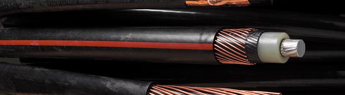
Image: Texcan
➡ Steven F Thomas. A lot of great responses. This cable was for a wind farm that had approximately 1 million linear feet of three phase cable, 3 million feet of single phase cable. What may not be obvious is that 3 core cables aren’t very useful. The size and weight of the overall cable would create an inordinate amount of cable joints or splices – and splices are failure points. We mandated no splices, unless absolutely necessary and must be approved by owner. The normal installation is direct buried, bundled, single phase cables. The US National Electric Code requires that cables be buried at least 1 meter (3 feet) underground, or a physical barrier be installed above. Our common requirement was 4 feet. In this case, these wires are considered concentric neutral wires, not a shield. Although they also provide an electrical screen, they are mostly a neutral/fault path back to the wye-grounded source. The construction of the cable is that the XLPE has a semi-conductor wrapped around it, and the neutral cables are in contact with that. Since the semi-con screen provides a complete non-metallic cover, is it important for the concentric wires to be evenly spaced?
➡ Kai Zhou (Senior Research Engineer at UL). Cable splice is usually the weakest point due to improper installation, contamination introduction, etc. Most of the cable joint failures in cable systems are from installation NOT from cable splice or cable terminations themselves. Since you have a really long run, what is your grounding design? The concentric neutral is also designed for shielding for power cable. To provide a uniform zero potential in case of cable semi-con problem. We have seen cable semi-con losing conductivity after aging, material absorption, etc. This kind of situation could be avoided by proper factory inspection and order inspection.
➡ Reply Steven F Thomas. You are correct, my experience is that splice failures are almost always installation error. The most common Root Cause was overheating, of which analysis showed that electricians were skipping the wire brushing to remove the aluminium-oxide layer that is not visible to the eye. It “looked” clean and shiny, so they skipped that step, I have seen papers from both 3M Electrical and Tyco Electronics indicating that renewable sources are much more susceptible to cable failure from this mode due to the high load cycling inherent in renewables. Both independently indicated that shear bolts splices & connections are much less likely to do this. If you can’t ensure the electricians will do an important step – then you need to change the step. We now mandate shear-bolt connections.
➡ Paul Knapp (Principal Engineer at UL). This can cause issues because the shield is not uniformly divided around the cable and arcing may occur in the unshielded space under the right conditions.
➡ Ben Lanz (MV HV Cable Reliability Consultant). Paul, I agree. At steady state an uneven concentric wire system might work but wide enough gaps and during transient conditions increased voltage across the outer semiconducting shield might start burning, arcing and pitting from the outside inwards. In addition the velocity of propagation will change with the variation in the wire spacing making fault and PD location difficult.
➡ Tony Haggis (Director at Tony Haggis Consulting Ltd). It would be illegal in the UK as the Electricity Safety Quality and Continuity Regulations (UK Law) requires that all live conductors be surrounded by an earthed metallic screen. The primary reason is to prevent electrocution in the case of a cable strike. The earth gets pierced first so the current is diverted to earth rather than through the person holding the cable cutting tool.
➡ Martin Stephenson (Business Development Manager Cable Services). Tony there are also “protected hydraulic cutters on the market” which have extra long hoses and non conductive oil to protect the operator should they mistakenly go through an energised cable. Also insulated cable cutters are used typically by Jointers on LV cables.
➡ Rick Moynihan (Cable Jointer – Director Certus Cable Jointing Pty Ltd). The semiconductive layer and screen wires are at the same potential. The screen wire should be rated according to fault current carrying capacity, therefore the termination of the screen wires as required per onsite earthing specification is the critical factor. The screen wire distribution in this cable does not look nice, however I cannot see how it would affect the electrical performance of the cable if it meets the specifications for its use.
➡ John Szabados, PE (Senior Manager at Sargent & Lundy). Rick, I disagree with this. We are talking two separate functions. The screen is there for voltage gradients and keeping a zero references. The neutral is for line to ground faults which with proper protection employed and sizing is there for a very short time frame. There is no test verifying the neutral and shield are touching. According to IEEE, failures of cable mid span are primarily due to manufacturing defect. Of course contributing factors are the cable splices and inadequate installation by the Jointer but this rarely explains faults in midspan. If the cable is specified properly, having an asymmetrical neutral layout by itself is not an issue. However, it does bring to question the QC in the manufacturing process. Based on this, I would ask more questions and initially reject the cable.
➡ Craig Horn (EHV Cable Jointer). That cable would work better without any screen wires rather than random bunches of wires. If cost is such a issue why not opt for aluminium foil screen? I’d like to see the cable manufacturers specification Vs a type test.
➡ Steven F. Thomas Craig, I think we’re talking about two different systems. A grounded wye system requires a neutral ground path for fault current, an ungrounded delta system does not. An ungrounded delta does not short circuit when one phase goes to ground, it takes two phases before a short circuit occurs. The “shield” on an ungrounded system cannot provide an adequate path for fault current, whereas the concentric neutrals on a grounded wye can provide fault path as well as electrical “shielding” and mechanical protection. In this case, an aluminum foil is totally inadequate as fault current would vaporize the shield. We don’t use tape or foil shields normally, except for control wiring, but I’m doubtful of the ability of an aluminum foil to provide mechanical protection.
➡ Craig Horn (EHV Cable Jointer) Steven, I would not buy this cable no matter what system it was to used for. The spacing of the screen/ neutral wires will have a negative affect on the efficiency of the conductor due to poor stress control. Aluminium screens can be manufactured with specific current carrying capabilities to avoid vaporisation.
➡ Dan James (Technical Services Engineer – HV Senior Authorised Person at NG Bailey). It would affect the shields ability to handle the field uniformly I would think.
➡ Steven F. Thomas Dan, this concurs with what a cable expert at Tyco Electronics informed me that essentially the semi-con and concentric wires are creating a Faraday cage. If the wires are severely bunched as these are here, the electrical field is not evenly distributed and when it’s not evenly distributed PD can occur which is how XLPE insulated cables fail.
➡ Dan James (Technical Services Engineer – HV Senior Authorised Person at NG Bailey). Steven, what I would imagine would happen, not a expert though. Areas without evenly spaced ground wires would have a higher field. Deteriorating that part more so than areas with more and any imperfections, degradation would be amplified.
➡ Satish Buddhawar (Electrical High Voltage, Offshore). Dan I think yes, this would result in the field concentration near to the unevenly spaced concentric wires, leading to local heating and degradation. In the cables I have seen, there is usually a layer of aluminium foil over the copper wires to radially block the water and also to provide the complete shielding (Faraday cage).
➡ Kai Zhou (Senior Research Engineer at UL). Regarding the electrical shielding, it can be a problem, or not a problem. There is cable insulation semi-con for electrical shielding function. For good semi-con layer, this probably won’t give you an “electrical problem”, as long as your terminating the semi-con and copper shielding wire properly. But for bad semi-con (losing conductivity over time), it could be. In any case, you are losing mechanical shielding protection, one of the major functions for copper shielding wire. From a design point, this should not be accepted since it is not per the design. If I was the user, I would ask the manufacturer to resolve the issue.
➡ Matthew Hadsell (Manager of Engineering at Blattner Energy). First, this really depends on voltage. At 34.5kV (assumed because it is for wind farm), this cable will likely not have any issues. Some independent cable testing laboratories have evaluated this for wind farm applications and come to this conclusion. Neutral bunching happens with many manufacturers over my years of installing cable and a good rule of thumb is as long as there is at least one strand in each of the 90 degree quadrants of the circle the cable will perform as advertised. This is of course not ideal, but it also isn’t a disaster of a problem at this voltage level. Bunching typically happens at cable ends and you can cut off 20 feet or so to remove the problem, so good QAQC when installing can catch and eliminate the concern. If this is encountered on a project, don’t panic and call a reputable cable testing laboratory for a custom report and analysis.
➡ Dan James (Technical Services Engineer – HV Senior Authorised Person at NG Bailey). Matthew, I have only seen one independent 3rd party analysis, submitted to us by the cable manufacturer to show bunched neutrals was not critical, and we rejected it as a faulty report for several reasons. Some cable experts have said this is critical; others seem to think it wise to evenly space the neutral wires, but not critical.
➡ Joe Dowds. Well spacing should not matter the neutral or ground is there to take the current if the cable faults that’s it’s main purpose.
➡ Steven F. Thomas. Joe, is it reasonable to assume that the current form a fault shares equally on every wire? Perhaps not to start if it is truly a fault from inside the cable, but eventually it would spread to all. This would imply that heating from the individual wires would be a percentage per wire. In the case of the one picture, where about 50% of the wires are all bunched at the bottom, would this not also imply that 1/2 of all the heating from a fault was concentrated in that spot? Rather than spread in all directions, the majority of the heating is concentrated in that one spot – so what happens to the thermal limits of the cable jacketing material? I think spacing does matter, particularly if neutral sizing is reduced to limit induced losses, and is closely sized to not overheat the jackets.
➡ Roger Lauricella (Vice President Technical Services & Support MV & Substation Specialist at WECS Renewables). Seen examples over the years from various wind farm customers just like that, it’s usually overseas cable that does not get the rigorous testing and quality production you see in North America, definitely not something one should have excepted or utilised. There are enough challenges with UG cable on wind farms and this is not an acceptable one to allow to go through.
➡ Steven F. Thomas. Roger, I also have seen this with off-shore manufacturers, but this one was not. This was an American supplier.
➡ Arie M (Senior Technical Expert at Consolidated Edison New York). I enjoyed the comments and depth of knowledge of engineering community for this very specific cable construction topic. All aspects of this issue including operating voltage, specific design, normal and transient mode, and specific installation issues (cable cut and shielding wires displacing) were addressed.
➡ Uxio Ramos (Technical Sales Director in Behr Bircher Cellpack Iberica). Not acceptable at all. That will lead to failure sooner or later. Furthermore, we have seen CWS (copper wire screen) cables without the additional Cu copper tape and the screen wires would eventually be all displaced to the lower side of the cable once laid on the ground… then failure. Poor quality, in my opinion.
➡ Charles Shannon (Senior Application Engineer at IMCORP). Uxio, have you seen the bunching you mentioned when using Cu JCN or CIC?
➡ Uxio Ramos. Charles sorry, can you explain JCN and CIC?
➡ Charles Shannon. Uxio, JCN Jacketed Concertric Neutral cable and CIC Cable In Conduit in essence it’s JCN without the J and instead it’s in a flexible conduit like HDPE or something but the neutrals are exposed to any water that enters the conduit.
➡ Uxio Ramos. Charles many thanks for the clarification. The case happened in single core CWS 16sqmm 36 kV cable. As I stated, the screen did not have the additional Cu copper tape applied in this cases. The cable sheath was PE, the cable isolation was HEPR and there was a plastic foil separating the screen from the sheath.
➡ Thorsten Rösch (Technical Director bei HvCable Solution). The earth wire which are not spaced cannot bare 360 centigrade short circuit temperature the cable is not acceptable. One correction copper screen temp is 250 centigrade.
➡ Protection Engineer). Everyone correctly points out that the shield will effect and cable may get heated. But, that happens only in multi core cables due to proximity effect but what is shown here is a single core cable. So, if the cable is laid in perforated tray and the other cores are kept at 50D spacing, how will this non-uniform armour cause the cable to heat?
➡ Steve Park (Electrical Power System Testing, Maintenance, and Engineering Executive Leader). Just saw in an earlier post that this cable also has a separate shield so that makes my earlier comments moot. Perfectly distributed concentric wires are probably not absolutely necessary for full life as they are in contact with a semiconductor material that will aid in creating a uniform ground plane to evenly distribute the electric field. However, here we have a significant non-uniformity that is not acceptable. There are large areas that appear not to have any concentric wires and likely to result in a non-uniform electric field leading to accelerated insulation deterioration.
➡ Ivan Jovanovic (Managing Director Cable Accessories at G&W Electric Co). Hi Steven, this looks like a shielded XLPE cable with extruded semicon screen over insulation. Theoretically there should be no field outside the screen but practically in transient and impulse conditions semi con screen is not acting as a perfect conductor and you really want to have these copper screen wires evenly spaced and in good contact with screen so you don’t build voltage gradient that can lead to pitting. There may be an issue from thermal perspective as well. Wires are sized to carry short circuit current and if they are not evenly spaced it is possible to have a hot spots which can thermally degrade both outer jacket but even more critically cable insulation. So from both perspectives if I was in charge of the project I would not accept it.
➡ Kerry Willert (Executive Construction Manager/Director Operations). No substitute for quality products!
➡ Rakesh Pandey (Negotiator/Electrical Engineer/Global Sourcing). Is it underground cable? seems aluminum core with copper neutral. If the sizing of copper is correctly considered then I guess we can use it. ANSI/ICEA S-94-649.
➡ Sjoerd Keijzer (Infratechniek) Not acceptable. There will be a wrong magnetic field around the cable. There will be a concentration on the places where the wires still are and there will be a higher temperature so therefore the insulation value will decrease. The insulation ages much faster and the lifetime of the cable will decrease enormously.
➡ Actually had this exact thing happen to us on a project a few years back. WTEC cable. It made us from that point on photo the ends of each cable prior to any cable terminations. Dan James is right it effects the shielding ability and I think a heating aspect of the cable too? I can’t remember 100%.
➡ Marcin Ruta (Power Systems Engineer). Aren’t those neutral wires twisted around cable? It will be random but is it acceptable? What standard do you follow normally for it?
➡ Brian Kolker (Carpenter). Marcin, No I would think not evenly distributed any extra energy that the wires may pickup from lightning strikes or from the ground it’s buried in.
➡ Noel Chamberlain. I personally like uniform in everything I worked on , I am not a cable jointer, I am a linesman, though it does not look the best on the end view, if the cable meets all pre-commissioning requirements I do not see an issue, though I agree it does look a little shoddy.
➡ Concentric neutrals have two purposes, as the neutral, as well as distribute the electric field around the cable. Spacing is important from the field perspective only.
➡ Mark H (Technical Manager for Electrical Engineering). One would have issues with the EMC of the cable, also the fault carrying capacity for the cable as the earth fault travels down the screen. It would also seriously distort the zero phase sequence, so if your specification asked for it to the IEC standards then it is best advised to reject the cable based on quality grounds under the FATs and SATs. With that kind of screen you may get additional heating due to the effects of circulating currents. Therefore your current carrying capacity would be compromised, but how much more would depend on the HV cable lay too, and what other cables it may cross. It may kill someone also for obvious reasons as the conductor is not covered completely thus you would be found liable under the EAWA.
➡ Paul Churnock, PE (Project Manager at McClure Engineering-St. Louis MEP) Ignoring the electrical characteristics and performance issues, I would reject this cable on the merits of the manufacturer’s lack of proper quality controls. If this visible issue exists, what other less readily apparent issues exist with such a cable. As noted, the shear quantity of cables necessitates proper material meeting the specified characteristics. The subsequent cost and down time necessary to mitigate and remedy potential failures far outweighs allowing non-conforming product.
➡ Faran Kaplan (Vice President, Sales Engineering). It’s not a neutral, it’s a ground. It’s designed to allow for equal radial distribution of corona discharge so that the insulation integrity is maintained.
➡ Axel Born (Cost and Value Engineering bei Siemens / Kabelexperte). At the cable ends the wires will be displaced by the cutting process. The real arrangement could be found by opening the cable some cm distance away from the cut end of cable.
➡ Abdul Kader (Business Manager HV/EHV Middle East). Axel, you nailed it.

Cable Terminations | Heat Shrink | Cold Shrink | Push-On | MV HV Medium & High Voltage
Nexans
Thorne & Derrick distribute the complete range of medium/high voltage electrical equipment manufactured by Nexans – this includes Euromold bushings for use with oil fluid or gas insulated switchgear or transformers and associated screened separable connectors according to both IEC (Euromold) and IEEE (Elastimold) for the termination, connect+disconnect of MV-HV cables onto power distribution systems. To protect power systems against high voltage surges resulting from lightning or switching a complete range of surge arresters are available to be used with Euromold connectors in 11kV/12kV, 24kV and 33kV/36kV voltage classes.
Key Product Categories: Duct Seals | Cable Cleats | Cable Glands | Electrical Safety | Arc Flash Protection | Cable Jointing Tools | Cable Pulling | Earthing | Feeder Pillars | Cable Joints LV | Joints & Terminations MV HV
➡ Read: Thorne & Derrick Announce Distribution Agreement & Contract With Nexans


