

Step-by-Step Guide for a 33kV T-Boot Termination
Published 08 Aug 2025
In this guide, Harvey Ross (HV Harv) demonstrates the key stages of a 33kV T-boot termination on a Nexans GT1 incomer. This process requires accuracy to ensure a watertight seal, maintain insulation integrity, and meet manufacturer specifications. Using specialist tools – including the Ripley Tools, US15 Pro Max, US02 & US10, as well as the ALROC LH2 – Harvey shows how each stage can be completed efficiently and to a high standard. All tools featured are available from Thorne & Derrick, jointing tool stockists, suppliers & distributors, trusted by HV professionals worldwide. The video below shows the full process, with our step-by-step breakdown following.
jointing Tools Used in This T-Boot Termination
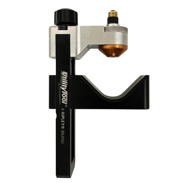
Ripley US15 Pro MAX
High-precision insulation removal tool designed for fast, consistent results on medium and high-voltage cables.
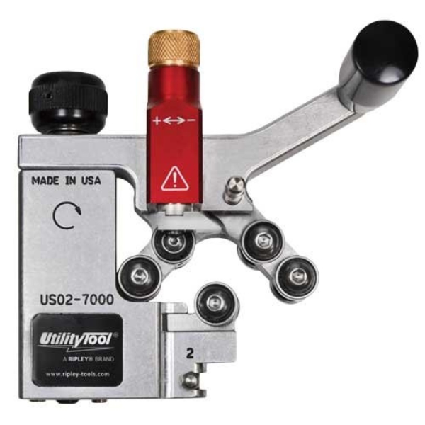
Ripley US02
Reliable semi-con screen removal tool ensuring smooth, damage-free stripping for high-voltage cable preparation.
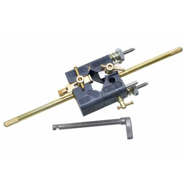
Ripley US10
Lightweight tool engineered for quick and precise chamfering of conductor ends to improve termination quality.

Alroc LH2
Heavy-duty cable cutter with a flexible cutting head for easy access to cables in confined spaces.
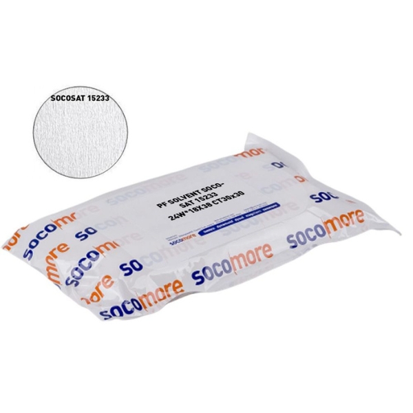
PF CLeaning Wipes
Industrial-grade wipes for effective cleaning and surface preparation during cable jointing and termination work.
All of these tools are available from Thorne & Derrick (Power and Cables) – trusted by LV, MV & HV professionals for safety, precision, and performance.
Cable Preparation & Initial Measurements
-
Measure the Bushing
-
Begin by measuring the bushing depth.
-
Measure back 285mm from the bushing end.
-
Sand 65mm of insulation to ensure a watertight seal.
-
-
Clean the Surface
-
Wipe the prepared surface thoroughly with a PF cleaning wipe.
-
XLPE Insulation Removal with Ripley US15 Pro Max
-
Remove Outer Insulation
-
Use the Ripley US15 Pro Max to make a circumferential cut, then transition to a spiral cut.
-
This tool excels in tight spaces and removes thick insulation with ease.
-
-
Finish the Cut
-
Use a hooked cable knife (a “hold-to-fall knife”) to flick out the final insulation section.
-
-
Remove Water Barrier & Copper Tape
-
Strip off the water blocking layer.
-
Remove the copper binding tape.
-
Clean the outer sheath again with a PF wipe.
-
Install Mastic & Prepare the Screen
-
Apply Water Mastic
-
Apply mastic around the cable as per kit instructions.
-
-
Bend Back Copper Screen Wires
-
Fold the screen wires back neatly in preparation for earth bonding.
-
Stress Control & Semi-Con Removal
-
Measure for Stress Control Tube
-
Mark 65mm from the screen cut to guide the positioning of the stress control tube.
-
-
Remove Semicon Layer
-
Use the Ripley US02 to remove the semi-conductive layer down to 30mm.
-
Tie off and sand as necessary for a smooth surface.
-
Cable Stripping & Chamfering
-
Strip Primary Insulation
-
Using the ALROC LH2, set the blade to the depth of the lug barrel.
-
Strip the insulation cleanly.
-
-
Chamfer the Conductor
-
Use the Ripley US10 to add a smooth chamfer to the end of the insulation.
-
This compact tool creates a clean finish, reducing stress points.
-
-
Prep Conductor
-
Tape the conductor end to prevent strand splay.
-
Clean the insulation and apply the termination grease (usually supplied with the kit).
-
Connector Assembly & Final Termination
-
Install Stress Control Tube
-
Slide it down to the 65mm marker created earlier.
-
-
Install Lug
-
Prep the conductor.
-
Slide on the lug and shear it off according to manufacturer torque ratings.
-
Clean and reapply grease.
-
-
Fit the T-Boot
-
Apply termination grease to:
-
The lug
-
Stress control tube
-
Inside of the T-body boot
-
-
Slide the boot on facing the correct direction.
-
Final Steps: Earth Bonding and Securing
-
Mount the Termination
-
Push the booted termination onto the bushing.
-
Fit the cleat to secure the assembly.
-
-
Dress Earth Wires
-
Straighten and align the copper screen wires.
-
Use one wire to wrap and secure the bundle for a clean finish.
-
Complete 33kV T-Boot Termination
What you now have is a fully installed Nexans 33kV T-boot termination, completed with precision using high-quality Ripley cable preparation tools.
Want to place an order for the tools used in this termination? Contact our team of experts – offering 40+ years of industry experience, we distribute the most extensive range of 11kV 33kV 66kV MV HV Medium & High Voltage Cable Joints, Terminations & Connectors from manufacturers including Südkabel, 3M, Prysmian, Nexans Euromold, Elastimold, Pfisterer CONNEX & SEANEX and Shrink Polymer Systems.


