Cable Pull Calculations – Installing & Pulling Heavy Cables

Published 22 Dec 2020

Texcan Wire & Cable Products

Texcan provides electrical and electronic wire and cable products for power distribution, control, industrial automation, automotive, premise wiring, and networking applications.

Guest Article By Blair Sackney, Dec 2020

Texcan | Major Projects & Engineering Support

This article contains my technical opinion and is for general information purposes only. 

Cable Pulling LV MV HV

Image | Allteck Line Contractors Inc | Empowering Lives, Connecting Communities

Cable Pulling Large Cables

Calculations

It’s good design practice to perform a cable pull calculation for cable pulling and cable laying runs that might be difficult. Doing this early in the project allows for cable sizing and routing options that are often not available late in the game. Pull calcs are relatively easy to do but surprisingly few engineers or contractors use them.

The type of damage commonly created by excessive pulling forces will typically pass DC HiPot or VLF acceptance testing. Medium Voltage cables are especially susceptible to this kind of damage.  It can result in partial discharge, leading to premature failures, commonly after 5 or 6 years of use.

While hand calculations can quickly spiral in complexity, there is software available to help simplify the process. Personally, I like Southwire’s Cable Pull Calculator, but a quick search will result in several other on-line options. Calculators are also available in most electrical modelling software.

The process involves inputting a few cable and pull set up parameters to verify that pulling forces will not result in cable damage. These parameters include gauge size, the number of conductors, cable OD and weight, raceway type and size, and each pull segment.

Performing more pull calcs and comparing them to real site experiences will result in an improved ability to make accurate assumptions. Pull calcs are more an art than a science as the calculations involve a lot of big assumptions making many other parameter assumptions rounding figures.


Cable Pull Calculations - Large Cables

Figure 1: Conveyor sheaves can significantly reduce sidewall bearing pressure if installed


Side wall bearing pressure (SWBP), the radial force imposed at the bends, is by far the most common limiting factor. Excessive SWBP, usually visible in flattened armour or stretched jackets, can result in insulation damage which decreases cable life.

Common misconceptions that have only minor effects on the resulting pull calculations:

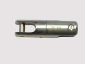
Maximum Pulling Tension – For power cables, this is usually not a limitation as the basket grip or pulling equipment usually limit pulling tensions before the conductors.

Upsizing the Conduit – Although you must maintain code required maximum fill requirements, upsizing conduits doesn’t lower tensions or SWBP by much.

Incoming Tension Assumption – Don’t sweat +/- 25 lbs on incoming tension assumptions as that will be a rounding figure in the final pull. However, using a cable feeder to push the cable in access points can help.

What does help:

Advance Planning & Field Communication – Can the field handle the reel you are specifying? Can it be placed where your pull calculation starts? Is there room to lay down cable for hand pulls or refeeds?

Straighten Out the Run – The fewer bends, the better. After two 90ᵒ bends, SWBP rises quickly.

Reduce run lengths – This reduces pulling tensions.

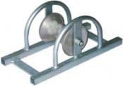
Bigger Conduit Sweeps and Sheaves – This makes a big difference to the SWBP. You should ensure that the cable minimum bend radius limitations are respected. That big 24” OD sheave is probably too small!

Tighter Coefficient of Friction (COF) Assumption – This parameter makes a huge difference in the final numbers. 0.35 is a common COF number for most common PVC jacketed industrial cables or regular building wire pulled through existing conduits. For a new installation with a good lubrication plan and experienced installation crew, 0.25 could be a more aggressive number. Southwire uses 0.15 for their no lube building wire products in PVC conduit.

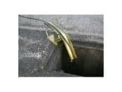
Pull Boxes / Assist Tuggers – Add pull boxes to break the pull up into sections (pull out through the manhole and refeed back in). If the cables can be accessed in the middle of the run somewhere, properly set-up assist tuggers can also break up the run.

Reverse the Pulling Direction – Pull calculations are directional.

Use Equipment or Cable Products that Reduce COF – No lube cable, hydrophobic pulling ropes, Southwire SIM reels, cable tray rollers, etc., …

The final few bends might be hand pulled, reducing the need to include those sections in the cable pulling calculation. Be careful not to overbend the cable during these manual pulling steps.

Cable pull calculations can save a lot of field issues and help ensure a long, trouble-free service life of your big cable runs. A little extra effort upfront can save a lot of trouble down the road.


THORNE & DERRICK

Cable Pulling Equipment

Thorne & Derrick distribute an extensive range of Cable Pulling & Laying Equipment to enable the safe installation of fibre and copper cables within the telecommunications industry. Safely installed cables reduces operational and maintenance requirements to the network and reduced service interruption to telecom cables, wires, ducts, cabinets and exchanges – products include cable spiking tools, conduit rods, cable lubricant, cable socks and cable rollers.

Further Reading