Nexans 240–300mm² Multi-Joint – Medium Voltage Cable Joint Installation
Medium voltage cable jointing requires reliability, consistency and safe installation practices. The Nexans 240–300mm² Multi-Jointis designed to simplify medium voltage jointing while maintaining high electrical performance for demanding power distribution networks.
The Nexans video below explains the purpose of the Multi-Joint system, its key design features and an overview of the installation process used when jointing medium voltage power cables.
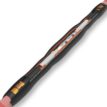
The Nexans Multi-Joint is part of the JTS heat-shrink cable joint range, designed for medium voltage cable connections where dependable electrical insulation and environmental protection are required.
The joint uses an integrated triple-layer heat-shrink tube combining stress control, insulation and conductive functions into a single component. This design helps simplify the installation process and reduces the number of components required during jointing.
Compact medium voltage cable joint design
Integrated triple-layer tube technology
Simplified installation process
High electrical insulation performance
Suitable for demanding power distribution networks
Key Advantages Of The Nexans JTS Joint Design
The JTS technology used in Nexans Multi-Joints introduces several improvements compared with traditional heat-shrink cable joints.
Reduced installation steps
Integrated stress control and insulation
Improved installation consistency
Compact joint dimensions
Enhanced electrical reliability
The triple-layer tube allows installers to heat fewer components during installation, helping shorten the jointing process and reduce the risk of installation errors.
Typical Applications For Nexans MV Multi-Joints
The Nexans Multi-Joint system is designed for use across a wide range of medium voltage cable installations including:
Utility power distribution networks
Industrial electrical infrastructure
Substation cable connections
Energy and infrastructure projects
Medium voltage cable repairs and extensions
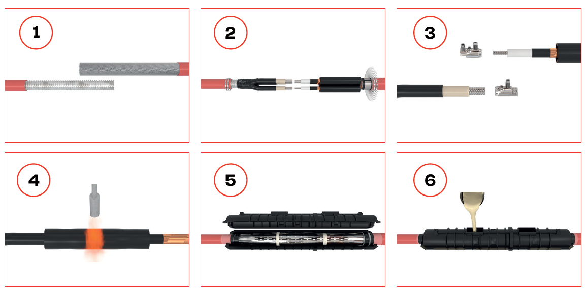
Overview Of The Installation Process
The Nexans video demonstrates the general workflow for installing a 240–300mm² Multi-Joint. While specific installation procedures must follow the manufacturer’s instructions, the process typically involves the following stages.
1. Cable Preparation
Position and align the cables
Measure and mark the joint centre
Remove outer sheath and prepare cable layers
Clean the cable surface prior to installation
2. Conductor Preparation
Strip conductor insulation to the required depth
Install the mechanical or crimp connector
Ensure proper conductor alignment
Remove sharp edges or burrs before recovery
3. Electrical Stress Control
Apply stress control materials around the connector area
Install conductive pads or mastic where required
Prepare the joint area for heat-shrink recovery
4. Heat-Shrink Joint Recovery
Position the triple-layer tube over the joint
Apply heat evenly from the centre outward
Allow the tubing to fully recover around the cable
Ensure a smooth and sealed joint surface
Environmental & Mechanical Protection
Once installed, the Nexans joint provides mechanical protection and environmental sealing. The system includes components designed to restore cable screening continuity and protect against external conditions.
Heavy-wall outer protection tubing
Screen continuity components
Moisture and water ingress protection
Resistance to chemicals and environmental exposure
High mechanical strength and impact resistance
These design features help ensure long-term reliability in both underground and industrial cable installations.
Compatible Cable Types
The Nexans JTS joint range is compatible with a variety of medium voltage cable constructions including:
Single-core polymeric cables
Three-core medium voltage cables
Cables with copper wire screens
Cables with copper tape screens
Cables with aluminium tape screens
This flexibility allows the same jointing technology to be used across multiple network configurations.
Choosing The Correct MV Cable Joint
Before selecting a medium voltage joint kit, several key factors should be considered:
Nexans designs and manufactures advanced cable systems and terminations for electrical power transmission and distribution networks. Their range includes medium voltage cable joints, cable terminations and connectors used to connect, repair and extend power cables across industrial, infrastructure and utility applications.
Nexans cable accessories are engineered for dependable electrical performance across low voltage and medium voltage networks, supporting installations such as substations, renewable energy systems, industrial plants, utilities and electrical infrastructure projects.
Thorne & Derrick, Experts in Equipment for Explosive Atmospheres, are specialist suppliers of Nexans cable accessories in the UK including solutions for connecting and protecting 11kV, 24kV and 33kV power cables used in energy, industrial and infrastructure installations.
On Friday 27th March, Thorne & Derrick will be taking over the bench at the Faraday Centre Ltd Power Group Event #2.
We look forward to welcoming clients, suppliers and service providers to the High Voltage Power Industry.
We’re gearing up for the Faraday Power Group Event #2, bringing together organisations from across the UK and beyond to collaborate, innovate, and strengthen safety standards across the electrical power landscape.
Join the likes of Alroc, Ripley, 3M, Penta and the Thorne & Derrick team for Live Demonstrations of the latest HV Cable Preparation Tools for Jointers alongside our manufacturers
We are committed to building cross-sector engagement across the Electrical Power Industry.
The Faraday Power Group
The Faraday Power Group is a collective of companies based in the North of England, working together to promote innovation, improve safety standards and support the evolving needs of the electrical power industry.
The upcoming event hosted at The Faraday Centre will bring together industry professionals, manufacturers and technical specialists for networking, knowledge sharing and live demonstrations.
Location
The Faraday Centre Ltd
The Wilton Centre Annexe
South Building
Wilton Centre
Redcar
TS10 4RF
Thorne & Derrick
Thorne & Derrick are Specialist Electrical Distributors of products to provide safe and reliable LV HV Cable Termination, Jointing, Installation & Power Systems from 600V to 66kV.
How to Lock Out and Tag Out a Marechal Socket Outlet
Electrical safety is a critical priority in industrial environments. When servicing or maintaining equipment connected to a power source, proper Lock Out Tag Out (LOTO) procedures are essential to prevent accidental energisation.
This guide explains how to safely lock out and tag out aMarechalsocket outlet, ensuring compliance with site safety requirements while protecting personnel from electrical hazards.
Why Lock Out and Tag Out a Marechal Socket Outlet?
Marechal socket outlets are engineered for safety and reliability, however all electrical systems must be correctly isolated before maintenance or servicing begins.
Lock Out Tag Out helps to:
Prevent unintended reconnection of power
Protect personnel from electric shock or arc flash
Maintenance, inspection or repair work is taking place
Connected equipment is being serviced or modified
There is risk of unexpected energisation
The outlet or plug is damaged
Temporary electrical isolation is required
Equipment Required
Required Safety Equipment
Marechal-compatible socket outlet lockout device
Personal safety padlock
Lock out warning tag
Appropriate PPE
Step-by-Step: Locking Out a Marechal Socket Outlet
1. Identify the Correct Socket Outlet
Confirm the socket outlet supplying power to the equipment and verify the correct isolation point before proceeding.
2. Notify Affected Personnel
Inform nearby workers and responsible personnel that isolation will take place to prevent accidental reconnection.
3. Disconnect the Plug
Safely unplug the Marechal connector and ensure all connected equipment has stopped operating.
4. Apply the Lockout Device
Install the lockout device over the socket outlet to physically prevent reinsertion of a plug.
5. Secure with a Safety Padlock
Attach your personal safety padlock. Only the person carrying out the work should retain the key.
6. Attach the Lock Out Tag
The lock out tag should clearly display:
Warning message such as “Do Not Operate”
Name of responsible person
Date of isolation
Reason for lockout
This provides clear visual communication across the worksite.
7. Verify Isolation
Confirm the outlet cannot be energised by testing that a plug cannot be inserted or power restored.
8. Carry Out Maintenance Work
Once isolation is verified, maintenance or servicing can safely proceed.
9. Removal of Lock Out and Tag
Ensure tools and personnel are clear
Confirm the area is safe
Remove lock and tag personally
Notify personnel before re-energising
Marechal Electric Safety Solutions
Marechal socket outlets and decontactors provide safe electrical isolation for industrial power applications including generators, motors, distribution systems and hazardous area installations.
Correct Lock Out Tag Out procedures ensure safe maintenance practices while maintaining compliance with industrial electrical safety standards.
The Complete Guide to Stokbord Sheets & Cable Covers
For utility contractors and civil engineers, the risk of “striking” buried infrastructure is a daily operational hazard. Whether it’s an 11kV distribution line or a 132kV transmission cable, the consequences of accidental damage are severe, ranging from costly power outages to life-threatening injuries.
Enter Stokbord, the industry-standard solution for heavy-duty underground cable protection.
While Stokbord is widely known as a versatile recycled plastic sheet, in the utilities sector, it serves a specific, critical purpose: providing a high-impact, shatter-proof barrier over MV (Medium Voltage) and HV (High Voltage) cables.
In this guide, we explore why Stokbord has largely replaced concrete and tile tapes, the specifications you need to know (including ENA TS 12-23) and how to choose the right protection for your project available here at Thorne & Derrick.
What is Stokbord?
Stokbord is a heavy-duty protection board manufactured from 100% recycled polyethylene. It is chemically inert, rot-proof, and exceptionally tough.
In the context of power distribution, Stokbord is used as a mechanical barrier installed in the trench directly above underground cables. Its primary job is to withstand the impact of hand tools (like spades) and offer significant resistance to mechanical excavators, alerting the operator to the presence of a cable before damage occurs.
Key Characteristics:
High Impact Resistance: Unlike concrete, which can crack or shatter, Stokbord absorbs energy and does not splinter.
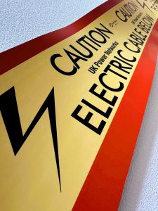
High Visibility: Typically supplied with a red background and a yellow “Caution Electric Cable Below” strip, offering an unmistakable visual warning.
Lightweight: A single person can easily handle Stokbord sheets, significantly reducing manual handling risks compared to heavy concrete tiles.
DNO Approved:It is the preferred protection material for most UK Distribution Network Operators (DNOs), including UKPN, ENW, and SSE.
Which Stokbord Product Do You Need?
At Thorne & Derrick, we stock the full range of Centriforce Stokbord solutions, catering to voltages from 11kV up to 400kV.
1. Stokbord Cable Covers (The Standard Tile)
This is the traditional format rigid sheets (typically 1 metre in length) that are laid over the cable and interlinked. They are ideal for protecting high-voltage connections where a robust physical barrier is required.
Specifications: Our stock meets ENA TS 12-23 (Class 1 & 2) and National Grid TS 3.05.07 requirements.
2. Stokbord Drum (The Safety Revolution)
The Stokbord Drum is a game-changer for site safety. Instead of individual tiles, the protection is supplied as a continuous strip on a reel.
Safety Benefit: It can be unrolled directly into the trench from the surface. This removes the need for operatives to enter the trench, eliminating confined space risks.
Speed: Installation is up to 30x faster than laying individual concrete or plastic tiles.
Alternative: Tapetile
For lower voltage applications (typically 11kV or street lighting) where a heavy rigid board isn’t specified, Tapetile is the standard alternative. It is a flexible, recycled plastic roll that offers visual warning and moderate protection, bridging the gap between simple warning tape and heavy-duty Stokbord.
Technical Specifications & Approvals
When procuring cable protection, “compliance” is the keyword. Using non-compliant materials can lead to project rejection by the DNO.
ENA TS 12-23 Compliance
Most UK utilities require protection that adheres to Energy Network Association Technical Specification 12-23. Stokbord sheets undergo rigorous impact testing to ensure they can withstand strikes without penetrating the cable below.
Class 1:Heavy-duty impact resistance (often required for 132kV+)
Class 2: Standard impact resistance (common for 33kV)
Dimensions & Thickness
While dimensions vary by DNO specification, standard thickness usually ranges from 6mm to 12mm
Length: 1000mm (standard tile)
Connection: Tiles feature pre-drilled holes and are supplied with plastic jointing pegs to lock them together, preventing gaps from forming during backfilling
Installation Guide: Best Practices
Correct installation is just as important as the material itself. Always refer to your specific DNO’s engineering standards (e.g., UKPN ECS 02-0019), but the general procedure is as follows:
Bedding:The cable should be bedded in fine fill (sand) to prevent damage from stones.
Placement: Place the Stokbord cover centrally over the cable.
Standard Depth: Typically, the cover is placed 75mm to 150mm above the cable crown. This gap is crucial it ensures that if an excavator bucket hits the board, the force isn’t immediately transferred to the cable.
Jointing: Butt the 1-metre tiles together and insert the plastic peg through the pre-drilled holes to secure the joint.
Backfill: Carefully backfill over the covers.
Warning Tape:For High Voltage installations, an additional Underground Warning Tape is often placed 200-300mm above the Stokbord for an early visual warning.
Why Choose Stokbord Over Concrete?
We frequently get asked if concrete tiles are “better” because they feel heavier. In modern utility construction, the answer is almost always no.
Feature
Stokbord® (Recycled Plastic)
Concrete Tiles
Impact Behavior
Deforms and absorbs shock; shatter-proof.
Brittle; shatters on impact, creating sharp debris.
Weight
Lightweight; prevents repetitive strain injury.
Heavy; high risk of manual handling injury.
Installation Speed
Fast (especially with Stokbord Drum).
Slow; requires heavy lifting and careful placement.
Rot/Chemicals
Inert; 100% rot-proof.
Can degrade over decades in acidic soils.
Protect Your Infrastructures
At Thorne & Derrick, we are leading distributors of Centriforce products, supplying projects across the UK and internationally. Whether you are working on a wind farm connection requiring 132kV Type A covers or a local 11kV diversion using Tapetile, we have the stock and technical expertise to support you.
The Klauke EK30IDML and EKM60ID Revolution
In the demanding world of industrial electrical installation, the goal is always a perfect balance between speed and precision. Traditional crimping methods, while reliable, often introduce an issue: the management of crimping dies. For every cross-section change or conductor class adjustment, an engineer must pause, locate the correct die and perform a physical swap.
Innovative dieless technology, embodied in tools like the KlaukeEK30IDML and EKM60ID, is fundamentally changing this workflow. By moving away from fixed-die systems, professionals are now achieving a “gas-tight” connection with more versatility and significantly less downtime.
Whether you are working in a cramped control panel or on a major industrial installation, these tools are designed to think with you.
The standout feature of both the Klauke EK30IDML and its larger sibling, the Klauke EKM60ID, is the dieless indent system.
How it works: Instead of selecting a specific hexagonal die for a specific lug, the tool uses a patented indent profile that automatically adjusts its depth and force based on the resistance of the connector.
No more lost dies: No more searching through a heavy kit bag for the right size.
Reduced Error: Eliminates the risk of using the wrong die for a specific lug size, a common cause of joint failure.
Versatility: Perfectly suited for compacted conductors and fine-stranded conductors (Classes 2, 5, and 6) according to DIN VDE 60228.
EK30IDML: The Panel Builder’s Best Friend
The Klauke EK30IDML is the lightweight champion of the range. Weighing in at just 1.95kg (including battery), it is designed for ergonomic, one-handed operation in tight spaces.
Crimping Range: 6mm² to 120mm² (Cu).
Crimping Force: 30kN.
Battery: 10.8V Li-Ion with a 40-minute charge time.
Head Design: Closed, flip-top style and rotatable 350° for maximum accessibility.
EKM60ID: Power & Intelligence for Industrial Scaling
When the job requires larger cross-sections, the Klauke EKM60ID steps up. It features a unique two-stage telescopic cylinder that ensures optimal force is applied regardless of the cable size.
Crimping Range: Up to 240mm² (Cu) and 240mm² (Al).
Crimping Force: Variable 30kN – 60kN.
Smart Technology:Includes Bluetooth connectivity for the Klauke i-press app, allowing you to export crimping reports and verify the quality of every single joint.
Safety First: Available in the VDE Orange range, providing 1000V insulation for working in the vicinity of live parts.
Why Professionals use Klauke tools
Working with high-voltage and high-current systems requires trust in your equipment. As a specialist distributor Thorne & Derrick provide not just the tools but the technical expertise to ensure your team is equipped correctly.
Key Benefits of the ML Series:
Automatic Retraction:The tool automatically retracts once the correct pressure is reached, ensuring a perfect crimp every time.
LED Lighting:Integrated work lights for dark switchgear cabinets.
Battery Compatibility: Choose between Bosch or Makita battery platforms to match your existing tool fleet.
Cable cutting and crimping toolsmanufactured by Klauke are renowned for high-quality, electrical connection tools for cable crimping, cutting and punching – special cable tooling solutions for applications in a range of different sectors.
Klauke tools are used by electrical contractors, cable jointers and linemen for underground cable and overhead conductor crimping and cutting on power, transmission and distribution networks including LV MV & HV systems, 11kV-33kV up to 132kV – this includes battery, hydraulic and ratchet type cable cutters.
Battery operated cable crimping toolsare made from the highest quality materials, rust proof and surface finished with a reputation for providing a long service live, consistently delivering safe electrical cable crimping connections for low and high voltage applications, 6-400sqmm. See also:Cable Cutters – Battery Type.
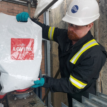
Compound Box Filling Compound end boxes rarely get attention — until one fails. Across ageing networks, replacement of compound-filled end boxes is becoming more frequent, particularly where original insulation systems have deteriorated and air insulation is not practical because...
Nexans 240–300mm² Multi-Joint – Medium Voltage Cable Joint Installation Medium voltage cable jointing requires reliability, consistency and safe installation practices. The Nexans 240–300mm² Multi-Joint is designed to simplify medium voltage jointing while maintaining high electrical performance for demanding power...


 The Faraday Power Group


 Protect Your Infrastructures