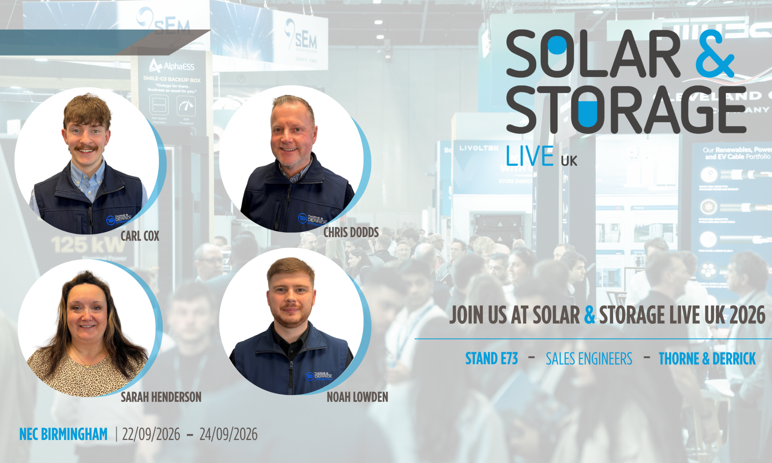
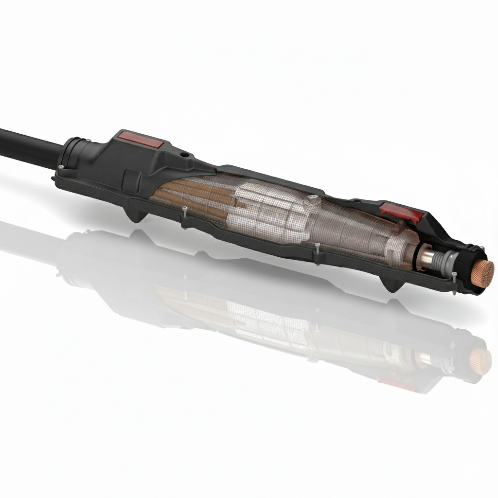
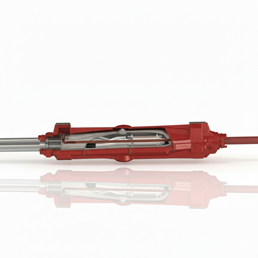
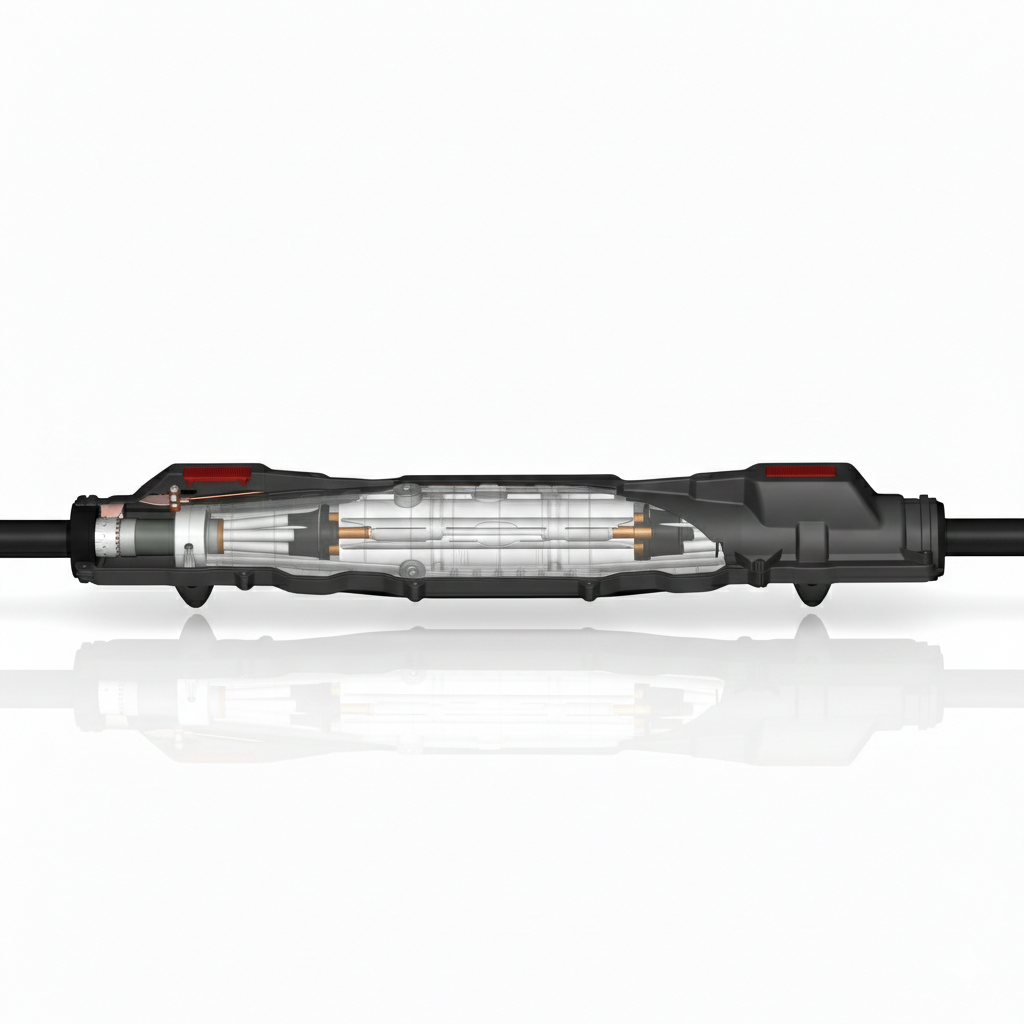
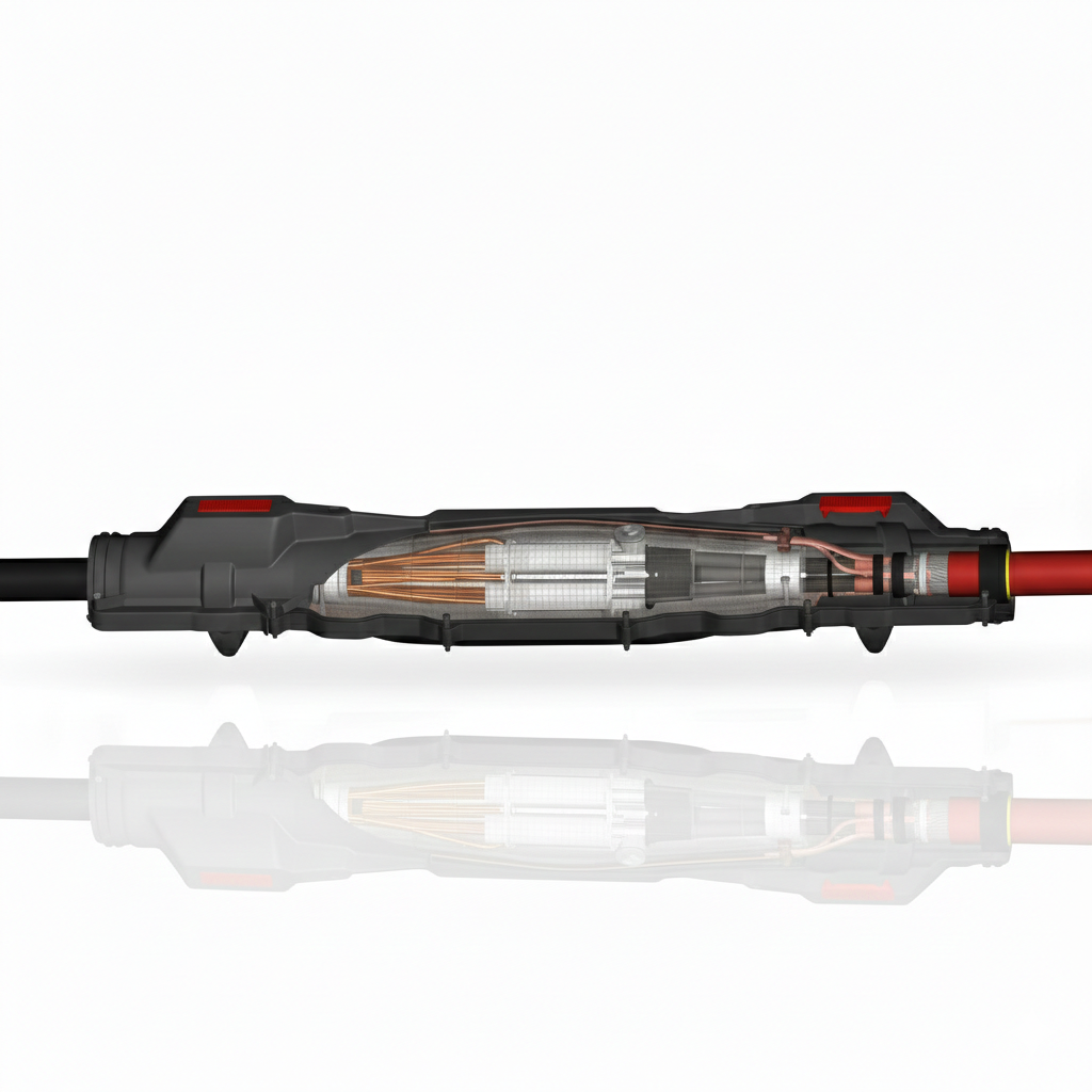
Thorne & Derrick will be Exhibiting at Solar & Storage Live UK 2026 at the NEC Birmingham from 22nd–24th September, showcasing our support for HV Cable Accessories, Joints, Terminations, Separable Connectors, Cable Tooling and Grid Connection Products used across solar, battery storage and renewable energy infrastructure projects.
Visitors can find Thorne & Derrick on Stand E73, where our team will be available to discuss products and technical support for Solar EPCs, high voltage jointing contractors, installers, utilities, contractors and developers working on UK and international projects.
Solar and battery energy storage projects rely on dependable electrical infrastructure to connect, protect and energise cable systems safely. From solar farm cabling and substation connections through to transformer, switchgear and grid connection works, Thorne & Derrick support the supply of specialist products used throughout the installation process.
Visit Thorne & Derrick on Stand E73
At Solar & Storage Live UK 2026, the Thorne & Derrick stand will focus on products used in the construction, connection, maintenance and operation of solar and battery storage infrastructure.
Visit us on Stand E73 to speak with our team about:
HV Cable Joints & Terminations
Cable joints, terminations and separable connectors for 11kV, 33kV and 66kV applications.
Cable Preparation Tooling
Cable preparation, crimping, cutting and stripping tools for jointing and termination works.
Cable Protection Systems
Cable ducting, troughing, sealing and protection products for site infrastructure and cable routes.
Cleats, Clamps & Fixings
Cable cleats, clamps and fastening systems for safe and secure cable installation.
Lugs, Glands & Connectors
Cable lugs, glands and connectors for electrical connection and installation works.
Substation Safety Equipment
Electrical safety equipment for workers operating around HV systems and grid connection infrastructure.
Live Tooling Demonstrations on the Stand
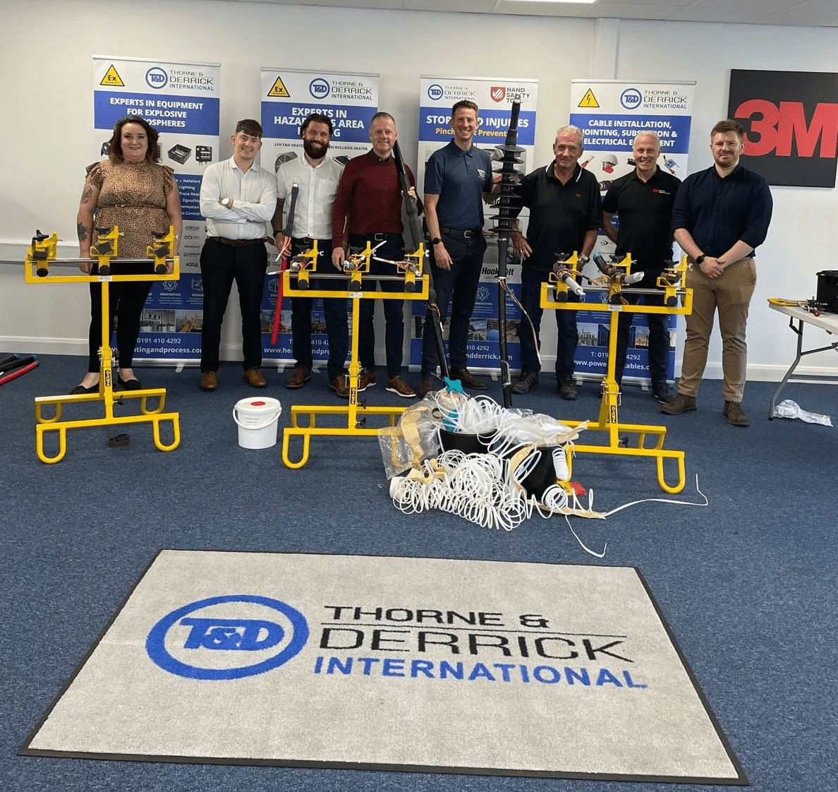
Live tooling demonstrations will be taking place on Stand E73, showcasing cable installation, preparation and jointing tools used by cable jointers, installers and contractors working on high voltage cable systems.
The demonstrations will provide visitors with the opportunity to see selected cable preparation, crimping, cutting and stripping tools in action, while discussing suitable tooling for solar farm, battery storage, substation and grid connection projects.
This hands-on element of the stand is designed to support practical conversations around cable preparation, installation efficiency, tooling selection and safe working practices on site.
Supporting Solar EPCs & High Voltage Jointing Contractors
Thorne & Derrick are specialist distributors to Solar EPCs and high voltage jointing contractors, supporting the design, construction and maintenance of UK and international energy infrastructure projects.
Our product range supports the connection of 600V and 1500V solar cables into combiner boxes, inverters and transformers, as well as the energisation of switchgear for high voltage grid connections.
As solar farms and battery energy storage systems continue to grow in scale, the need for reliable cable accessories, tooling, connectors and substation equipment remains critical to safe and efficient project delivery.
Products for Solar, BESS & Grid Connection Projects
Thorne & Derrick supply a wide range of LV, MV and HV electrical products used across renewable energy infrastructure, including:
Our technical knowledge, responsive customer support and extensive supply capability allow us to support contractors and project teams with products required for installation, connection, maintenance and energisation works.
Featured Product Areas
Cable Joints & Terminations
HV cable accessories for solar farms, substations, BESS projects, transformers and grid connection applications.
Separable Connectors
MV and HV connector solutions for switchgear, transformers and electrical equipment used in renewable energy infrastructure.
Cable Tooling
Preparation, stripping, cutting, crimping and jointing tools used by installers and high voltage cable jointers.
Cable Protection
Cable cleats, clamps, troughing, duct sealing and protection systems for safe and reliable cable installation.
Meet the Team at Solar & Storage Live UK 2026
The Thorne & Derrick team will be available across the three days of the event to discuss upcoming project requirements, product selection, technical applications and supply support.
If you are involved in solar, battery storage, substation, grid connection or wider renewable energy infrastructure projects, visit Stand E73 to speak with us about how we can support your next project.
Event Details
Event
Solar & Storage Live UK 2026
Location
NEC Birmingham
Dates
22nd–24th September 2026
Stand
E73
Opening Hours
Tuesday 22nd September: 09:30–17:30
Wednesday 23rd September: 09:30–17:30
Thursday 24th September: 09:30–16:00
Visit Thorne & Derrick on Stand E73
Since 1985, Thorne & Derrick have provided specialist technical support and express delivery from extensive UK stocks to worldwide destinations.
At Solar & Storage Live UK 2026, we will be showcasing our support for the solar and battery storage industry with a focus on HV cable accessories, cable jointing, terminations, tooling and grid connection products.
Visit Thorne & Derrick on Stand E73 at the NEC Birmingham from 22nd–24th September 2026.
The following article on Cable Asset Management has been published with the kind permission of ERPA.
ERPA (Electric Power Reliability Alliance) are a collaborative practitioner community that works to advance awareness and understanding of electric power reliability.
ERPA are a “practitioner-to-practitioner” collaborative community, bringing proven and practical resources and shared experiences to practitioners in the industrial and commercial markets.
A reliable power system is the lifeblood of any production facility, distribution system, data center or business.
Cable Asset Management
A Scientific Approach to Cable Asset Management
By Ben Lanz, Director, Applications Engineering, IMCORP. Member, EPRA
Power Cables | Cable Care
Power cables are one of the most commonly overlooked power system assets and are, by default, typically addressed reactively after failure. They are also one of the most misunderstood. This article provides insight into how new scientific findings on cable care address these misunderstandings. In this article I will provide insight into some of these findings through case studies, and I’ll explain how a holistic, condition intelligence-based strategy can easily double the expected life of most assets — including cables — and maximize reliability with optimal life cycle cost.
Most medium- and high-voltage cable systems consist of plastic and rubber (solid dielectric) insulation. A significant percentage of assets containing those materials are reaching—or have passed—their assumed 30- to 40-year end-of-life. Asset managers are now facing a significant challenge in balancing reliable power delivery with budget priorities. As new assets are installed, reliability professionals are asking, “how can we make cable systems last longer with higher reliability?”
Cable Asset Management Best Practices
This broad reliability question comprises several smaller and more practical questions, which have been answered here with input from cable owners from all over the world. With their help, we have assembled the largest condition assessment database of its kind—and the findings are good news for cable owners.
We discovered that to extend the life of medium and high voltage cables, there are two key things to consider when developing a reliability plan, supported by four best-practice recommendations:
A. Practice “cable care” techniques.
With the proper care and maintenance, aged cable systems can outperform new cable systems.
B. Eliminate physical stressors and extreme duty stressors.
With these additional stressors removed, it is possible to extend the reliable life of cable to 100 years— and beyond.
C. Follow best practices
Install and maintain over voltage protection.
Perform IR inspection of connectors.
Perform offline 50/60Hz PD testing to ID insulation defects.
Eliminate or minimize over voltage tests such as fault location ‘thumping’ and withstand/hipot testing.
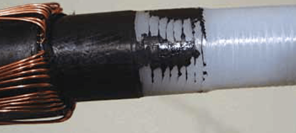
Medium and high voltage solid dielectric cable system insulation fails due to an erosion process associated with phenomena called partial discharge (PD).
PD is an electrical discharge (or ‘micro arcing’) that does not completely bridge the insulation. PD can arise from an extreme focus of electric stress, a lack of the appropriate solid insulation, or a combination of both.
A focus of electric stress, or stress enhancement, can be caused by issues such as accessory interface contamination, a foreign object, a protrusion of a semiconducting layer, or area of extreme moisture concentration. A lack of appropriate solid insulation filled by a gas, or a void, can be caused by such issues as:
a damaged semiconducting layer
overheating of the cable or accessory insulation
an insulation cut
a lack of accessory/cable interface void filler
or an incorrect accessory/cable interface dimension
Failure to use correct jointing tools can lead to catastrophic cable failures at the connection interface of cables (straight joints) or at their ends (cable terminations) – core screen thickness and strippability varies from cable to cable manufacturer therefore it is essential for the MV-HV cable jointer to set the cutting blade of the cable tool to the correct screen cutting depth, this is usually tested on scrap cable lengths prior to jointing.
PD, and its associated erosion process at a defect site, is rarely active at steady-state operating voltage unless the failure is imminent. PD is initiated when localized electric stress overcomes the local dielectric strength.
Voltage transients—fast, short duration electrical transients—are the primary driver to turn on PD and propagate insulation failure. The sources of transients include:
circuit switching
restoration activities, such as breaker operations and fuse re closures
fault location and withstand tests
momentary flashovers and grounds (momentary contacts with air insulated components)
complete faults elsewhere in the system
sectionalizers
capacitor banks switching
transformer tap changes
and, especially, lightning
Transients reflect and resonate within the power system and can increase in magnitude exponentially. Voltage transients typically occur in the microsecond to millisecond time frame. This is more than enough time for PD, which occurs in the nanosecond range, to turn on, erode the insulation, and turn off.
Successive transients can cause intermittent growth of a carbonized fault channel sometimes described as an electrical tree. As the electrical tree grows, the turn-on voltage drops, and eventually the PD is active at the operating voltage. The erosion process fails this insulation.
Industry Questions Answered with Science
Many questions have been asked about proper cable care over the last few decades. These questions have often been answered with reasonable theories, which have helped the industry make reasonably accurate asset decisions. But now, with the aid of scientific research, a more precise understanding is driving more optimal solutions.
Answers to some of those frequently asked questions now follow, and each is informed by this research:
D. Does cable only last 30 to 40 years?
Research indicates for most applications, provided there is no extreme loading or voltage events or discrete physical defects in the cable system, there are no known significant long-term aging mechanisms to cause cables to fail short of 100 or more years.
E. Does moisture fail cable?
No. Random moisture only creates a more ‘leaky’ or lossy insulation. Aside from losing a tiny amount of power to operate the cable, this is not problem.
However, in the extremely rare event that moisture concentrates due to the higher stress of an original manufacturing or installation defect, extreme voltage transient can cause local stresses to exceed the insulation strength, start carbonizing insulation, and creating a fault channel (electrical treeing).
F. Does cable fail rapidly once a carbon track is formed?
In the vast majority of cases, No. Most carbon tracks or ‘electrical trees’ are not active at the operating voltage and thus only grow during short voltage transients. They can take years—or even decades—to grow to failure.
G. Do installation defects fail quickly?
Installation defects often take years or decades to fail. Since the defect erosion process is only turned on intermittently and the fault channel path is driven by the highest stress path which often is not the shortest path, the growth rate can be surprisingly slow. The first failure is often associated with an installation or manufacturing defect. However, once a cable is a couple of decades old, we need to be
very careful as the voltage transients associated with the fault location process often damages the cable causing new defects.
H. Can DC or VLF tests at least detect most of the gross defects?
DC and VLF (very low frequency or 0.1Hz) present such different stress distributions in cable insulation compared to in-service and factory test conditions, most defects are missed. By adding dielectric loss or tangent delta measurements—or even PD measurements—a few more percent of defects can be detected.
That said, these approaches are generally less than a ten percent solution and unfortunately can cause damage without warning. Best practice recommends, these tests be kept to less than the line to ground voltage for less than a minute just to check for existing shorts.
I. Are most cable failures due to overheating?
Overheating is generally a connector problem, not a cable issue. Most failures are actually due to insulation defects, not overheating problems. However, in high load applications, termination and joint connector installation problems on aluminum conductors are notorious for overheating and damaging cable insulation systems.
J. Is helical copper tape a robust shield design?
Helical copper tape functions just fine in paper insulated cable systems, since it is in oil and moisture is kept out by a lead sheath. Solid dielectric cable only has a polymer jacket to protect it and does not stop moisture from causing corrosion, initializing a process of arcing and pitting from the outside inwards which is commonly observed on aged cable.
Generally concentric neutral and longitudinally applied copper tapes have been shown to have a much better long-term performance.
K. Are there any standards we can use test solid dielectric cable systems?
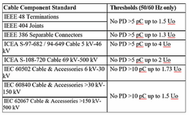
Quality tests by cable and accessory manufacturers are performed on all new system components at the manufacturing plant prior to shipping and installation. All factory-built products must meet standards such as ICEA (Insulated Cable Engineers Association) or IEEE (Institute of Electrical and Electronics Engineers).
The manufacturers’ quality control tests require 50/60Hz partial discharge (PD) diagnostics at an elevated voltage, with generally better than 5 or 10pC sensitivity [Table 1]. These standards can be used to judge the performance of cable system in the field.
L. What can be done to enhance longevity?
The recipe for cable longevity is to push quality to the earliest point in the life of the cable system, and then minimize any extreme duty cycle events. As early in life as possible a cable system should be baselined with an offline 50/60Hz PD test to check for insulation issues and an IR test under high load conditions to check for connector issues.
Once any necessary repairs are complete, confirm sufficient over-voltage protection is installed at all significant impedance change points (primary cable end points). Finally, monitor the cable system for any extreme over-voltage or overloading events (including, re closing on faults, thumping, withstand or Hipot testing). If such events occur, a new baseline for the insulation and connector will need to be established.
THORNE & DERRICK | Medium Voltage Cable Jointing Solutions
Network resilience requires advanced technology solutions manufactured from highest performance materials; if high harmonics, Sine wave distortion, AD8 protection, abnormal thermal cycling, high-water table, ALE of legacy PILC or general cable failure prevention to critical 11/33kV circuits matters to you, then talk to us.
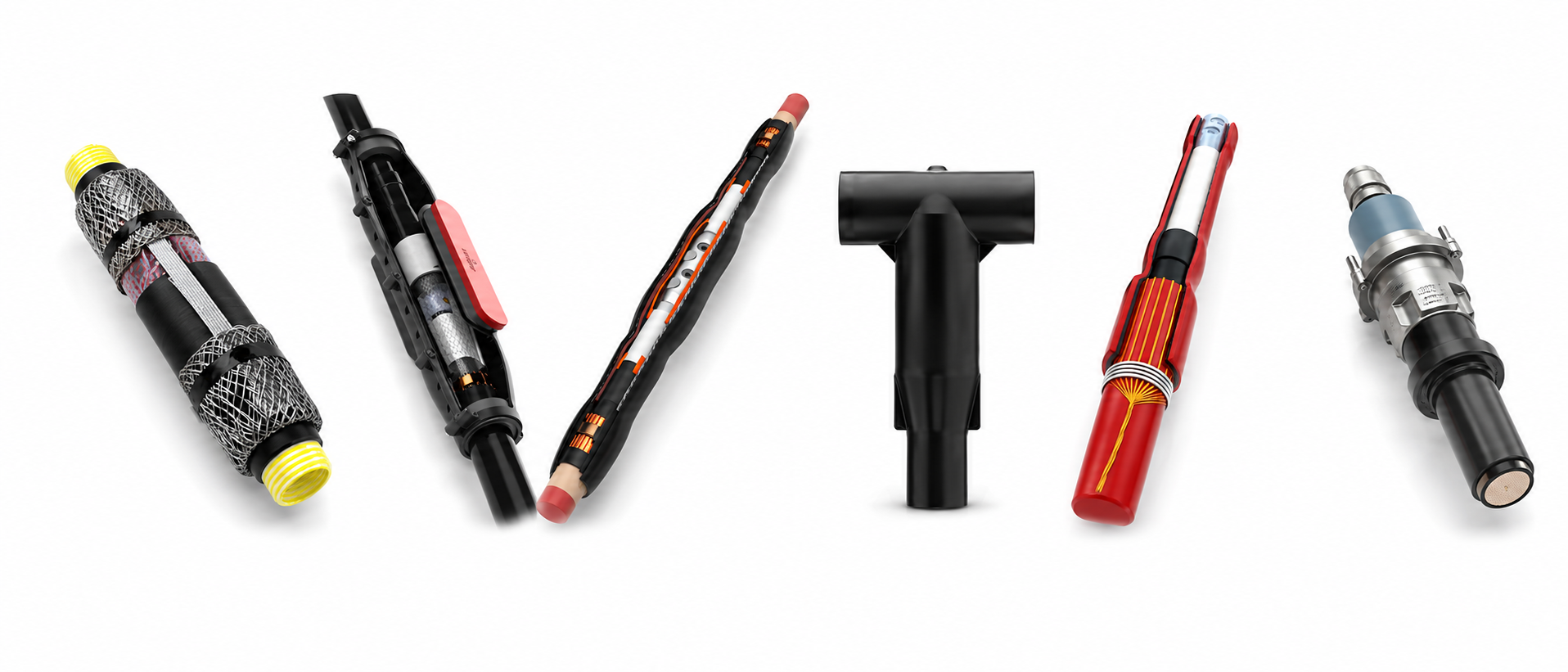
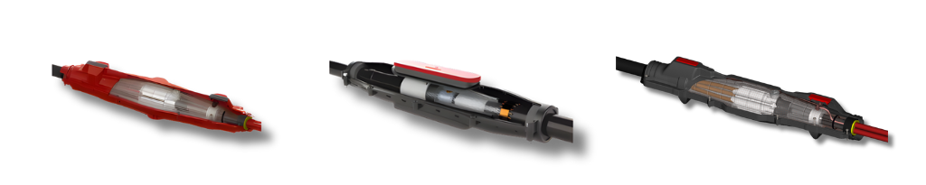
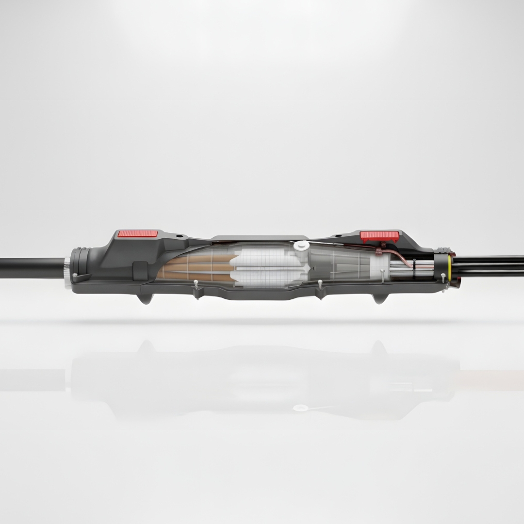
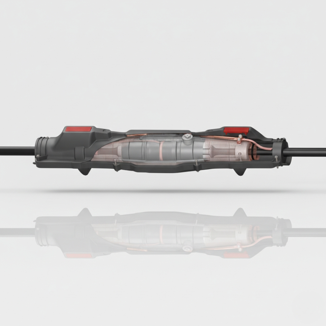
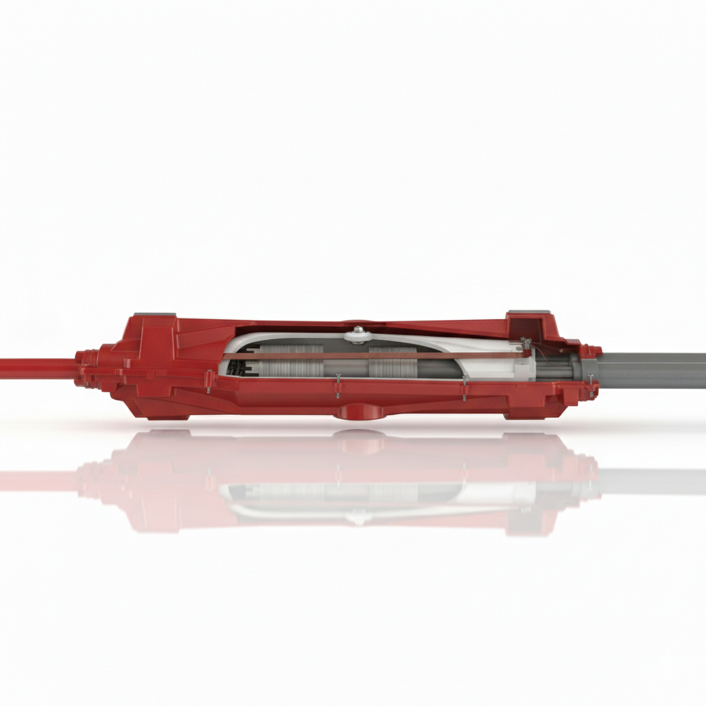
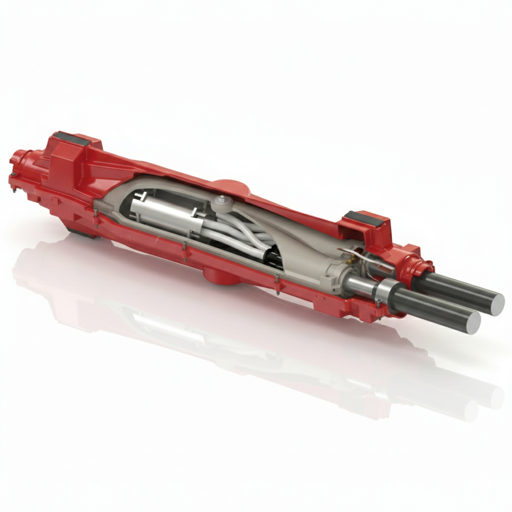
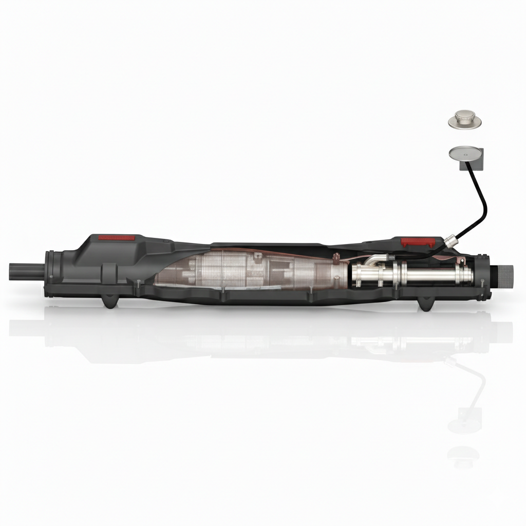
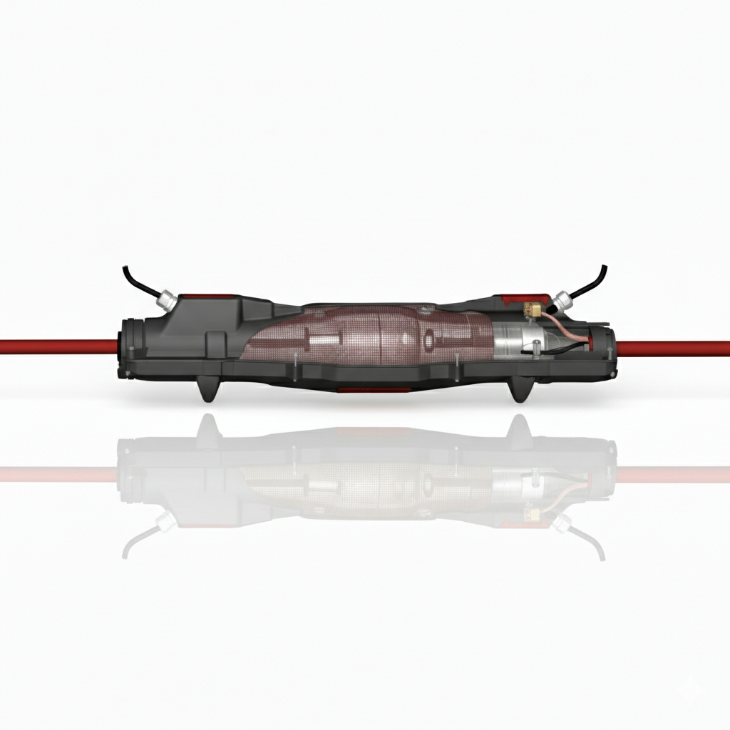
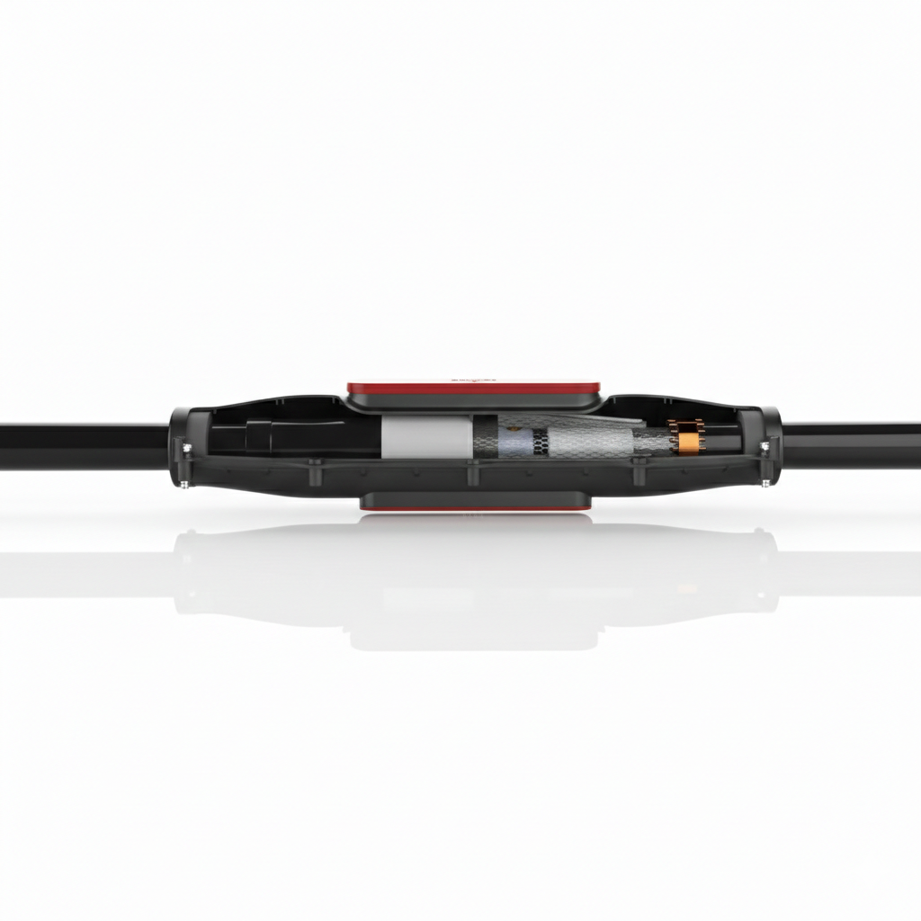
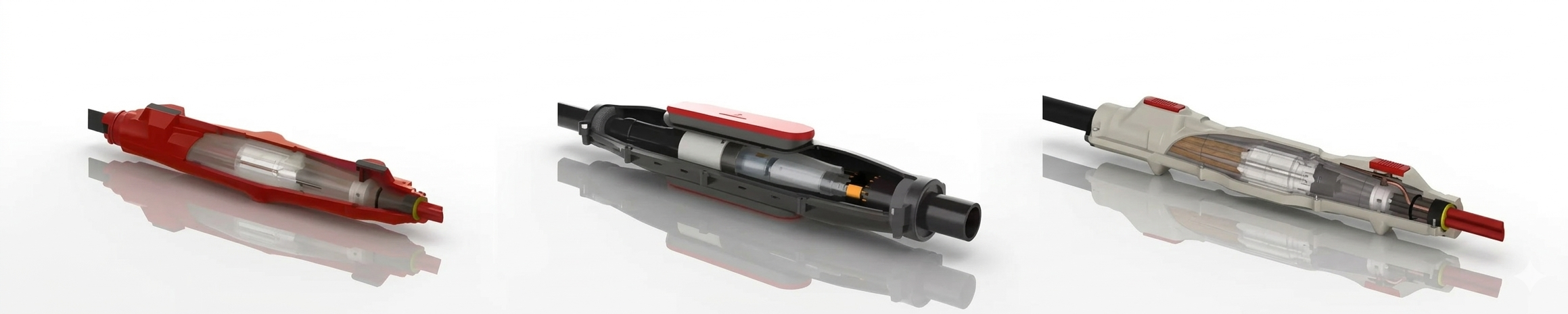
Cable Joints for Medium & High Voltage Cables |the Lovink range of cable joints provide high-performance for high-challenge applications including configurations for straight, transition, trifurcating-transition, branch and loop jointing of cables typically distributing electricity at 11kV, 24kV and 33kV; this includes connection joints for extensions and repairs for MV HV cables with XLPE, PILC & EPR insulation.
Lovink Enertech products are proven in service worldwide for network resilience, ease of installation, and long-term reliability.
Compound end boxes rarely get attention — until one fails.
Across ageing networks, replacement of compound-filled end boxes is becoming more frequent, particularly where original insulation systems have deteriorated and air insulation is not practical because separation distances are limited. In these situations, the replacement dielectric is not a minor detail; it is central to long-term reliability.
When specifying compound box filling for refurbishment works, the goal is not simply to refill the box. The dielectric has to maintain insulation performance over time, tolerate operational movement, and resist the conditions that caused deterioration in the first place.
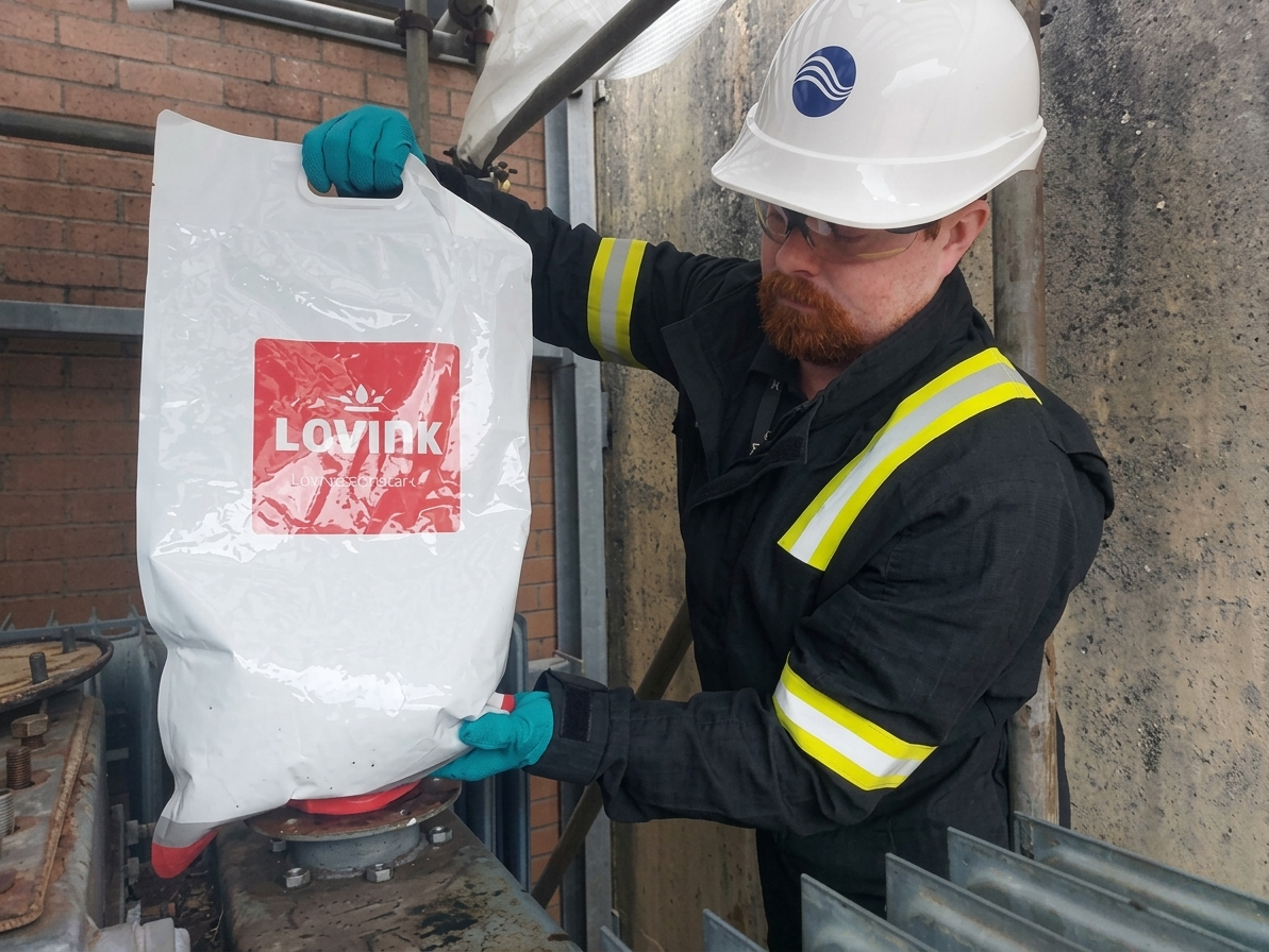
At Lovink Enertech, LoviSil® provides a purpose-engineered solution for compound end box refurbishment. Unlike curing alternatives, LoviSil® remains permanently fluid, allowing it to move with conductor expansion and contraction under load. Solidifying compounds cannot accommodate this movement; over time they form voids, and voids lead directly to partial discharge and eventual breakdown.
Why Compound Box Filling Matters
In MV end box refurbishment, the dielectric choice directly affects service life, insulation integrity and future maintenance. A fluid dielectric offers an important practical advantage because it can move with conductor expansion and contraction during load cycling, helping to reduce the formation of voids that can lead to partial discharge.
LoviSil® requires no mixing, can be poured straight from the bag, and does not require greasing of the box prior to installation. It is also fully compatible with residual pitch or bitumen, meaning complete removal of legacy compound is not always necessary.
With a minimum dielectric strength of 21 kV/mm, LoviSil® delivers insulation performance equivalent to XLPE. It resists moisture ingress and forms a sealing barrier if moisture attempts to enter, helping prevent migration deeper into the system.
Key Advantages
Permanently fluid dielectric – moves with conductor expansion and contraction under load
Reduces void formation risk – helping to minimise partial discharge and premature breakdown
No mixing required – can be poured straight from the bag for simpler installation
No box greasing needed – helping reduce preparation time on site
Compatible with residual pitch or bitumen – complete removal of legacy compound may not be necessary
High dielectric strength – insulation performance equivalent to XLPE
Simple re-entry – drainable for easier future maintenance and intervention
A Practical Maintenance Advantage
Re-entry is simple. Release the bolts at the base of the faceplate and the LoviSil® drains into a container. No cutting. No effort. Just drain and go.
For asset owners, this provides a cost-effective alternative to full end box replacement while restoring dielectric performance and extending service life.
Recent failures involving replacement compound-filled end boxes highlight a recurring issue: choosing the wrong dielectric solution only delays the problem.
Final thought: don’t pay twice — restore it once with LoviSil®.
Overview of the Lovink Cable Joint Range
Alongside solutions for compound box filling and end box refurbishment, Lovink offers a broad range of medium voltage cable joints designed for ageing infrastructure, upgrades, repairs and new connections across 11kV and 33kV networks.
Below is an overview of the 11 Lovink joint categories, each developed to suit specific installation and network requirements.
Lovink MV Cable Joints
A complete range of medium voltage cable jointing solutions for repairs, transitions, upgrades and new underground cable connections.
Transition Cable Joints
For connecting legacy paper-insulated cables to modern polymeric MV cables.
Compound-filled end boxes often only get attention when something goes wrong. But the choice of compound box filling has a direct impact on insulation performance, moisture resistance, re-entry and long-term reliability.
Where refurbishment is the preferred route, Lovink’s LoviSil® offers a practical and technically robust alternative to full end box replacement. Combined with Lovink’s wider MV joint portfolio, it supports utilities, contractors and network operators working to extend asset life and improve resilience across ageing cable systems.
Need Support with Compound Box Filling or MV Cable Joints?
Thorne & Derrick supply Lovink LoviSil® solutions and the wider MV cable joint range, with technical support for refurbishment, repairs and new cable connections.
Selecting the right cable cleat is a key part of designing and installing a reliable power distribution system. In environments such as industrial facilities, critical power and other electrical installations, cable cleats help ensure a short-circuit event does not escalate into major cable or equipment damage.
During a fault, electromagnetic forces rise rapidly and can cause cables to move violently. Correctly selected and installed cleats restrain cables during these brief but critical moments — supporting safety, equipment protection and overall system integrity.
This guide sets out practical steps to support cable cleat selection: understanding fault forces, the variables that influence cleat performance, and how to choose solutions that suit your cable formation, tray/ladder geometry and site constraints.
Fault Current Potential & Why It Drives Cleat Selection
Short-circuit events generate strong electromechanical forces between conductors. Cable cleats must restrain cables so that containment is maintained and damage risk is reduced. IEC 61914 provides methods and test requirements that help engineers assess performance against short-circuit forces. Forces are affected by peak fault current, cable spacing, cable formation (e.g., trefoil versus flat), conductor/cable diameter and cleat spacing.
Understanding these inputs helps narrow down suitable cleat types and installation approaches.
Peak short-circuit current influences the maximum electromagnetic forces.
Cable formation (trefoil/flat) changes how forces act between phases.
Cable diameter & spacing affect phase separation and load conditions.
Cleat spacing changes how much load each cleat must restrain.
LV vs MV/HV: What Changes for Cable Cleats
IEC 61914 defines LV cables as those rated up to 1.0 kV AC (or 1.5 kV DC). Above these levels, cables are treated as MV/HV for testing purposes. In practice, higher voltage systems can be associated with higher prospective fault levels, which increases the importance of verified cleat performance, correct cleat spacing and robust installation.
Key Factors That Drive Cable Cleat Selection
Cable cleat selection typically comes down to a handful of practical variables. Getting these right helps ensure compliance, performance and installability.
1) Short-circuit rating requirement
The cleat must be suitable for the prospective fault level, cable formation and cleat spacing used. Where fault levels are high, retention performance and mechanical robustness become critical.
2) Cable diameter & adjustability
Cleats must fit the actual cable OD and the selected formation. If diameters vary on-site, solutions with a wider usable diameter range can help reduce SKU complexity and simplify procurement.
3) Tray/ladder geometry
Rung/slot dimensions, access to fixings and allowable cleat spacing can dictate what works in practice. Always ensure the chosen cleat can be mounted correctly on the tray or ladder system used.
4) Installation workspace
Limited access (overhead, congested runs, risers) can make bolt tightening difficult. Consider how the cleat installs in real conditions: tooling, access underneath the rung, and whether installation must happen before or after cable pull.
5) Environment & compliance
Consider corrosion exposure, UV, temperature, and any project-specific requirements. Standards-based testing and appropriate materials (e.g., stainless steel and protective liners/coatings) are often important for longevity and cable protection.
Practical rule of thumb
Cable cleats aren’t just tidy cable management. They are a mechanical safety component designed to restrain cables during short-circuit conditions.
Start with prospective fault level and formation, then work outwards to spacing, mounting geometry and installation constraints.
When BAND-FAST Cable Cleats Are Typically Considered
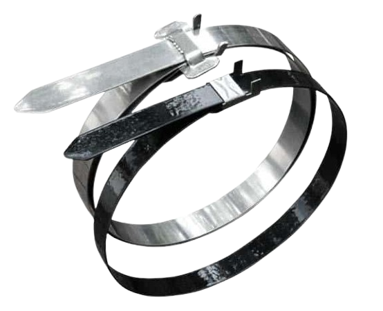
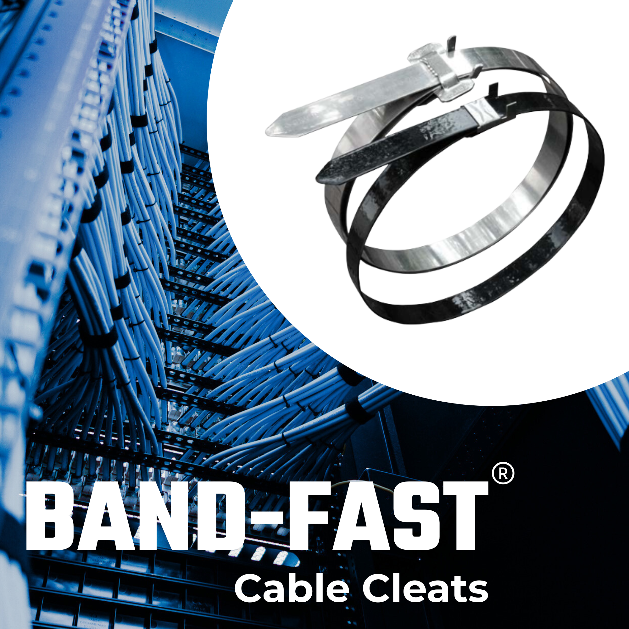
In high-fault applications and congested tray systems, installation practicality can matter as much as the short-circuit rating. BAND-FAST cable cleats are often considered where a robust retention solution is needed and where post-pull installation offers a practical advantage. Typical drivers include:
High retention requirement within the rated test envelope
Post-pull installation preferred to avoid interfering with pulling equipment/rollers
Reducing SKU complexity where cable diameters vary across projects
Tray Slot Width: Quick Compatibility Check
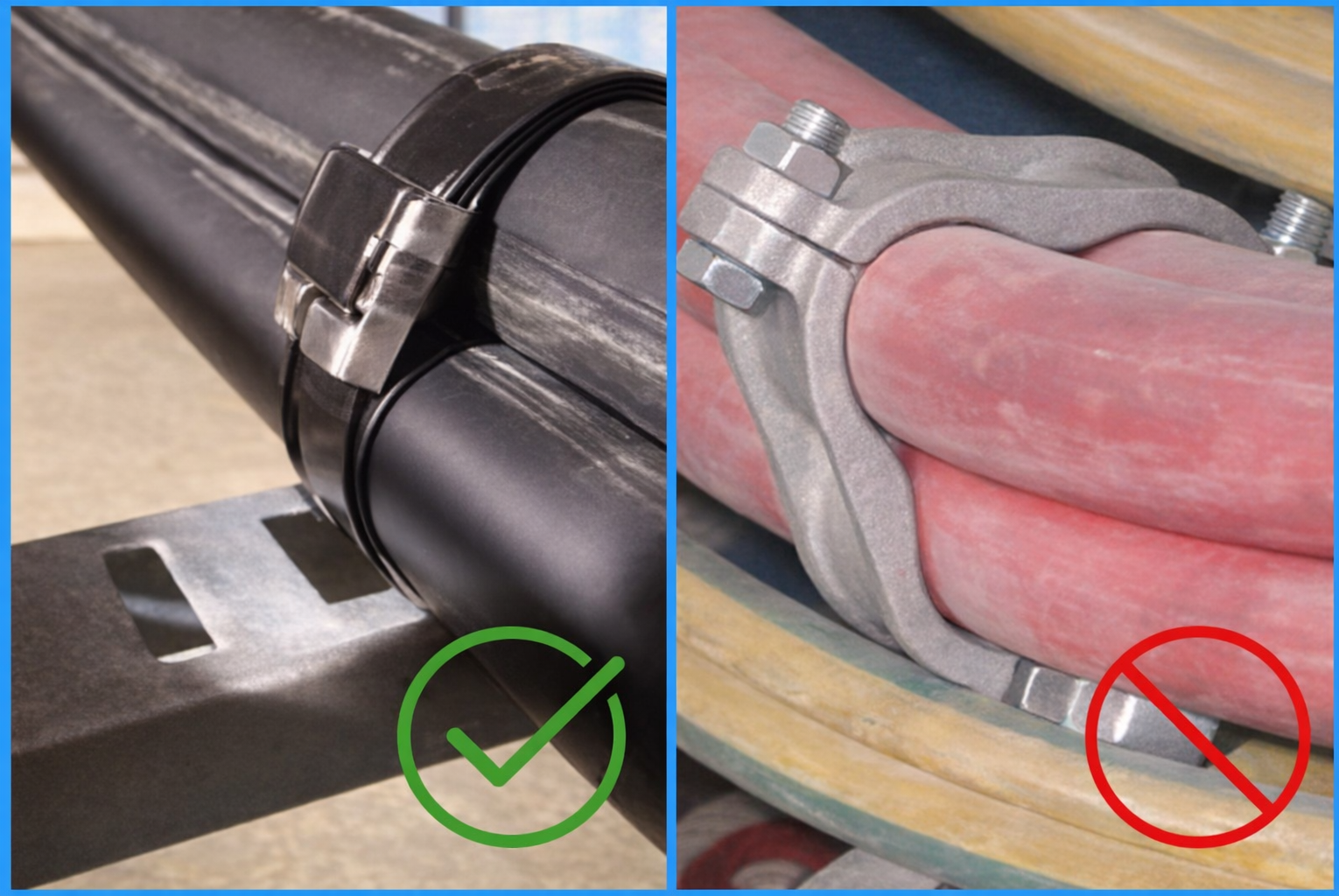
Before specifying band-style cleats, check tray or ladder slot dimensions. If rung slots are below the required width, feeding/locating the band can be inconsistent and another cleat style may be more suitable. Example minimum slot width guidance (confirm against the specific BAND-IT cleat/tooling selected):
5/8″ coated band: slot width ≥ 17.5 mm
5/8″ uncoated band: slot width ≥ 17 mm
3/4″ uncoated band: slot width ≥ 20 mm
Summary: How to Choose the Right Cable Cleat
Use this selection flow to keep decisions consistent:
Define prospective fault level and verify the required short-circuit rating.
Confirm cable formation (trefoil or flat) and actual cable outside diameters.
Set cleat spacing aligned to test declarations and project constraints.
Validate mounting geometry for the tray/ladder system (slots, rungs, access).
Account for the environment (corrosion/UV/temperature) and any project standards.
Choose an installation approach that works on site (pre-pull vs post-pull, access, tooling).
Specify BAND-IT Cable Cleats with Confidence
Tell us your cable sizes, formation, tray/ladder type and prospective fault level. We’ll help you identify a compliant, practical cable cleat solution for your installation.
Beyond The Net: Why HV & ATEX Demand Expert Partnerships
In an era of click-based procurement and AI-driven recommendations, a critical question is amplifying across energy and process industries. When lives and multi-million-pound assets hang in the balance, are your buying processes safe and robust?
For Thorne & Derrick International, the answer today is “probably not”. Thorne & Derrick has deliberately and clearly positioned itself not as a catalogue supplier, but as a solutions-based consultative partner adding high value expertise to energy supply chains globally.
What Thorne & Derrick Deliver
The Thorne & Derrick team of highly trained Technical Sales Engineers provides correct product specification and supply supplemented by value-added services. This includes supporting customers with system design, site survey, field training, product demonstration and CPD-accredited courses. In hazardous areas and high-voltage industries, where a single mis-specified component can trigger catastrophic system failure, this distinction isn’t commercial nuance — it’s a safety imperative.
The Risk in Digital-Only Procurement
The rise of online B2B marketplaces and impersonal web-based stores has transformed industrial purchasing, bringing speed and transparency to many categories but dumbing down decision-making and introducing error into customer carts. Beyond doubt in HV, ATEX, IECEx and DSEAR-regulated environments, digitisation carries some serious risks. Whilst products may appear dimensionally identical across three suppliers online, subtle yet critical differences in product specification can dangerously go unnoticed.
Never mind mis-selection — counterfeit is common; product faking is rife.
Quote
“Customers aren’t buying a commodity,” explains Chris Dodds, Sales & Marketing Manager at Thorne & Derrick International. “They’re investing in a service that assures delivered products will comply and ensure optimum performance with built-in safety and reliability. This requires deeper intelligence beyond the datasheet to include the operating context; understanding explosion protection concepts, T Class, Gas Group, bushing interfaces and complex high-voltage cable specifications and configurations. No dropdown menu captures that.”
Product Compliance & Installer Competence
The Thorne & Derrick philosophy underpins their business model: Sales Engineers undergo continuous professional development training in hazardous area and high voltage standards, product technology, selection, installation and application engineering. The investment upholds a core belief: Product Compliance & Installer Competence must exist alongside industry regulation and technology.
From 600V to 66kV, from Zone 1 to Zone 21, they are committed across the business to supporting the delivery of safe projects. The common thread isn’t product breadth alone; it’s the application of contextual intelligence to match equipment specification with site reality to deliver that safety.
Safety as a Shared Outcome
Thorne & Derrick support a sharpened commitment: Certified Products, Installed Competently. Certification validates the product’s design integrity and assurance emerges from the correct selection. Competency is assured by training and ongoing development to ensure the highest levels of installation workmanship. One without the other creates vulnerability.
The Human Layer in an Automated World
As the energy mix accelerates through renewables, decarbonisation, hydrogen, battery energy storage and innovation in hazardous area processes, the complexity of Certification and Compliance intensifies. Legacy knowledge alone no longer suffices. In this dynamic landscape, Thorne & Derrick International positions its Sales Engineers not as checkout order-takers, but as active participants in clients’ safety ecosystems.
Technology will continue reshaping procurement. But in environments where error tolerance is zero, the human layer of expertise remains irreplaceable. Thorne & Derrick International’s value proposition rests on a simple, sobering premise: the cheapest or fastest option isn’t always the safest. And safety, ultimately, isn’t purchased—it’s engineered through partnership.
For engineers specifying critical infrastructure, that expert partnership may be the most important component in the bill of materials.
Partner with Thorne & Derrick
In HV and hazardous area environments where error tolerance is zero, our Technical Sales Engineers help ensure correct selection, compliance and safe performance in the real world.
Celebrating Charlie & Ella’s Level 4 Sales Executive Apprenticeships At Thorne & Derrick International, we are proud to champion talent development and recognise the dedication required to achieve professional growth. We are therefore delighted to congratulate Charlie Baines and...
Thorne & Derrick will be Exhibiting at Solar & Storage Live UK 2026 at the NEC Birmingham from 22nd–24th September, showcasing our support for HV Cable Accessories, Joints, Terminations, Separable Connectors, Cable Tooling and Grid Connection Products used across...