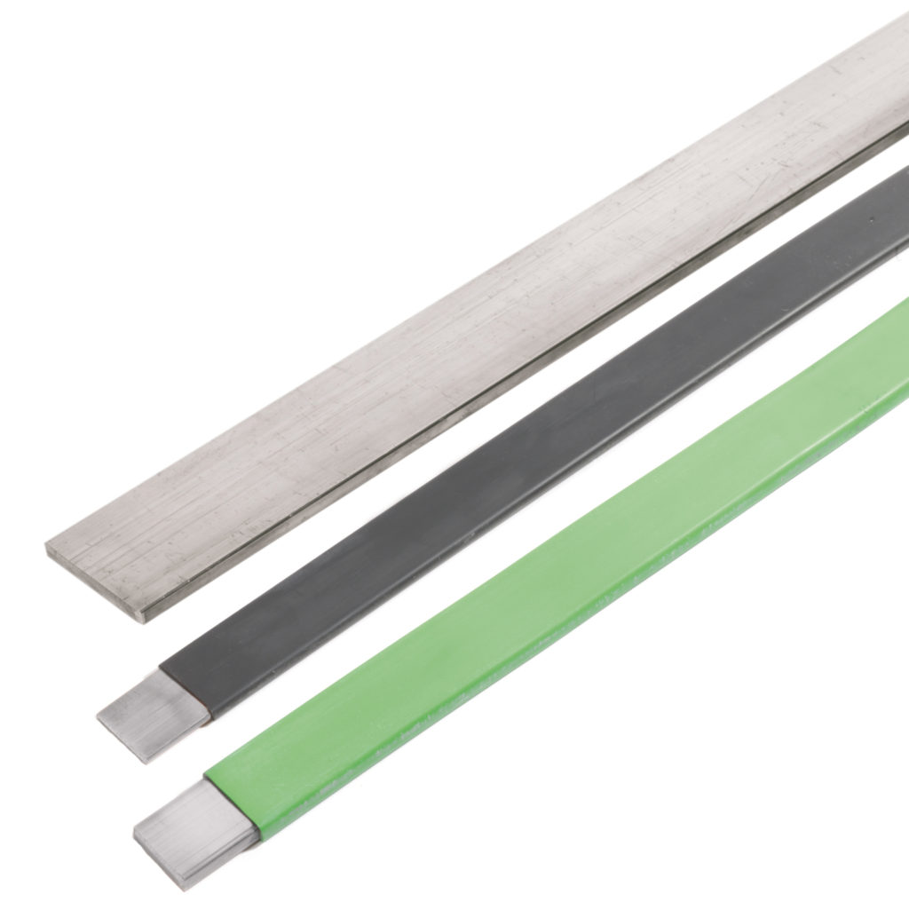
Systems Power RVCB (Retrofit Vacuum Circuit Breaker) Switchgear
Credit: Mikolaj Kukawski | Customer Networks Manager at ESM Power Ltd
Featured Manufacturer: Systems Power
MV HV Switchgear
Mikolaj is an experienced Private HV Networks Manager with a demonstrated history of working in the utilities and medium/high voltage (MV HV) sectors of industry.
Skilled in MV HV Electrical Power Distribution Systems operation, maintenance and asset replacement. Strong operationsprofessional with SAP experience up to 132kV for both private and DNO networks.
ESM Power design, deliver and manage LV MV HVelectrical networks safely, securely and economically – this includes ICP and DNO connections at LV, 11kV, 33kV and 132kV.
Switchgear MV HV | Thorne & Derrick distribute Nexans Euromold, 3M Electrical, PFISTERER Connex, Prysmian and Shrink Polymer Systems ranges of Joints, Terminations & Connectors to enable the installation and maintenance of electrical switchgear, transformers and substations.
T&D supply Cables, Accessories & Electrical Products for Low Voltage (LV 230V to 1000V), Medium Voltage (MV 3.3kV/11kV to 33kV) and High Voltage (HV 33kV to 132kV) networks.
JOINTERS BLOG
Subscribe now to our POWER NEWSLETTER– a monthly email circulation packed with news, projects, videos, technical tips, training information, promotions, webinars, career opportunities and white papers.
Includes access to our popular JOINTERS BLOG with contributions from utility professionals, linesmen and cable jointers working on MV HV EHV cables and overhead lines typically at 11kV, 33kV, 66kV and up to 132kV.
Thanks you Ahmed Metwally Electrical Transmission Specialist for allowing us to republish this article
Published Study for HV Cables Optimization through CIGRE-GCC 2019
Abstract
High Voltage Cables
The electric power transmission system of National Grid Saudi Arabia (a subsidiary of Saudi Electricity Company-SEC) includes a network of underground cables ranging from MV (13.8kV) to EHV (380kV) cable. The backbone of this power distribution network has a voltage rating of 110kV to 380kV with conductor cross-sectional area varying from 400sqmm to 2500sqmm.
The high voltage underground cable network has three different voltage ratings; 110kV, 115kV and 132kV. Prior to 2003, the electricity network was being operated and maintained by four individual utility companies having their own specifications and franchise areas;
132kV in the Central and Southern regions
115kV in the Eastern region
110kV in the Western region
National Grid initiated a study to standardize and optimize the designs for high voltage cables suitable for all high voltage ratings. The study started unifying the cables sizes and designs, verifying performance of existing network and analysing demand forecast.
Suitable designs and sizes were worked out and appropriate ways were looked into to optimize the design by implementing the relevant international standards and taking into consideration feedback from the maintenance and projects about existing cables.
Introduction to HV Cables
Utilities around the world are going for optimization of utilized equipment (reduce capital and operational cost). Therefore, Standards & Specifications Department of National Grid Saudi Arabia formed a team of experts to study the possibility of standardizing/unifying cable design to three sizes; 1200sqmm, 2000sqmm and 2500sqmm.
In addition, it will achieve financial savings as a result of this design optimizing.
Process flow for this study is shown below:
Study Process Flow
National Grid specifications have variety of high voltage cable conductor sizes which were based on IEC 60228 and the different operating areas requirements. However, based on ampacity required for each substation, National Grid is selecting 1200sqmm conductor size more often to cover load demands. And the other sizes 2000sqmm and 2500sqmm are the second most popular choices after 1200sqmm which can be applied for all substation requirements as shown in [Figure 1].
Reduction in Cable Layers
1. Reduction of Cable Insulation
The international standard IEC 60840 “Power cables with extruded insulation and their accessories for rated voltages above 30kV (Um = 36kV) up to 150kV (Um = 170kV) –Test methods and Requirements” does not specify the required nominal thickness of insulation for high voltage cables. But this is not the case with IEC 60502 which specify required nominal thickness of insulation for medium and low voltage cables.
However, the limitations of the insulation thickness for high voltage cables depends on nominal conductor electric stress which shall not exceed 8,0 kV/mm and the limitations of the insulation screen thickness depends on nominal insulation electric stress which shall not exceed 4,0kV/mm.
The required insulation thickness as pre National Grid specifications was 20.32 mm for 110/115kV cables and 21.6 mm for 132kV cables. These values satisfy the requirement of IEC 60840, but with high safety margins as shown in table 1 for 132kV cables.
Table 1
1200 sqmm,
132 kV cable
2000 sqmm,
132 kV cable
2500 sqmm,
132 kV cable
Insulation Thickness [mm]
21.6
The nominal Conductor electric stress [kV/mm]
4.92
4.67
4.59
< 8
The nominal Insulation electric stress [kV/mm]
2.62
2.69
2.77
< 4
Table 2shows parameters for 1200sqmm, 2000sqmm and 2500sqmm for 132kV cable and all the results are within the required range based on IEC 60840.
1200 sqmm,
132 kV cable
2000 sqmm,
132 kV cable
2500 sqmm,
132 kV cable
Insulation Thickness [mm]
18.0
The nominal Conductor electric stress [kV/mm]
5.65
5.48
5.31
< 8
The nominal Insulation electric stress [kV/mm]
3.26
3.34
3.43
< 4
2. Reduction of Semi Conductive Layers
The same principle of the cable insulation that the IEC 60840 does not specify the required nominal thickness for cable semi-conducting layers, the team made the changes in this layer based on the manufacturers experiences when it comes to operating the triple extrusion machine and trying to maintain the eccentricity of the cable.
National Grid involved thirteen (13) cable manufacturers around the world to study and check the minimum required thicknesses for semi-conduction layer which can fulfil the requirement of eccentricity based on IEC 60840 and as a result, the conductor shield and insulation shield reduced to 1.5 mm.
3. Reduction of Metallic Screen Layer
Different metallic screens are available based on National Grid specifications. Most common choice is copper wire with tape screen [Figure 2]. Its selection mainly depends on the project requirement such as radial water tightness features, electrical and mechanical properties.
However, all metallic screen types have a fundamental function to withstand the required short circuit current.
Therefore, a critical part of designing the metallic screen is to know how much an area of metallic screen can withstand the required short circuit, IEC 60949 ” Calculation of thermally permissible short-circuit current taking into account non-adiabatic heating effect” was used to calculate the required area of metallic screen of the high voltage cable that can withstand the required short circuit.
There are two ways to do short circuit calculation; using adiabatic temperature formula and using non-adiabatic factor. In this study non-adiabatic factor chosen, by using thermal constant of the media applied over either sides of the screen. Moisture impervious layers were applied to both sides.
This helped reducing area of copper wire screen from 280sqmm “as per a adiabatic calculations” to be 261sqmm “as per non-adiabatic calculation” and still fulfilled National Grid specifications to withstand 40kA for 1 second and provided good financial savings in the cost of the high voltage cable.
These reductions in the insulation thickness and metallic screen area have also increased slightly current capacity of the optimized cable comparing with the conventional cables being used in the network.
The below Table 3shows an example of the current rating values changes.
1200sqmm, 132kV cable
The load Current [A]
914
The permissible Cable current [A] – Insulation thickness of 21.6 mm – Metallic screen area of 280 sqmm
954*
The permissible Cable current [A] – Insulation thickness of 18 mm – Metallic screen area of 261 sqmm”
961*
+ 7
*Installation conditions: the standard trench of a single circuit in flat formation in a backfill duct bank at 1.45 m depth with 300 mm axial phase spacing, 40 ºC soil temperature, 2.0 ºC.m/W soil thermal resistivity (dry value), 1.2 ºC.m/W thermal backfill resistivity (dry value) and cross bonded system.”
Cable Manufacturers Production Capabilities
After the completion of the design of all layers of the cable, National Grid contacted several qualified cable manufacturers (local & international) and discussed the possibility of manufacturing cables with the suggested design and its effectiveness.
The responses received were consistent with the design provided by National Grid and its specifications were updated in 2018. Subsequently, manufacturers started production of the optimized cable size 1200sqmm which was type tested successfully.
Design of the System Test Loop
After getting the success capability from the cable manufacturer and the decision to approve the optimized design, it was type tested as per IEC 60840 in addition to a short circuit test in the presence of National Grid representatives to check the quality of the new design for the electrical and non-electrical tests, the main test loop included the following components; 50 m of cable test, two outdoor porcelain terminations, one straight joint and one cross-bonding joint based on the test loop in Figure 3.
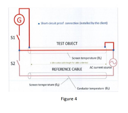
And the additional test to ensure metallic screen/sheath withstanding required short circuit was the short circuit test for which National Grid and DNV-GL “KEMA” made a procedure & the test loop The test loop is shown in Figure 4.
Financial Cost Savings
Local manufacturers were contacted for the calculation of financial savings as a result of the cable reduction and cost index [%] for HV is shown in table 4.
Benefits from this exercise in terms of financial savings in the capital budget in the next seven years were estimated to be about 25 million US dollars.
110kV, 115kV and 132kV Cables
Description
1200sqmm, Normal Design
1200 sqmm, Optimized Design
2000/2500 sqmm, Normal Design
2000/2500sqmm, Optimized Design
Cost Index %/Km
100
93
100
95
The Results
Financial savings by reducing thickness of insulation & metal cover area “metallic shield” without affecting quality and efficiency of cables
Standardization to three sizes only; 1200/2000/2500sqmm. As a result of this optimization, cable accessories will automatically be unified/standardized for specified models of cable joints and cable terminations
Reduction in the weight of cables up to 8.6% and overall cable diameter up to 9.6%. This will facilitate the installation of cable laying thus reducing the cost of civil works
By Ahmed Metwally
Currently Electrical Transmission Specialist at Saudi Electricity Company
Job Purpose
* Approve the pre-qualification of manufacturers for electric equipment such as Cables, Cable Accessories, Link Box, SVL and Cable Cleats & Clamps.
* Authoring and updating the company specifications based on the international standards.
* Attend various type tests to verify the produced equipment is in line with requirements.
* Provide technical studies that help to use new methods in electrical transmission projects based on national and international researches.
Job Roles & Responsibilities
* Very strong experience at Extra High Voltage and High Voltage Cables and Accessories (500kV, 400kV, 380kV, 230/220kV, 132kV, 115/110kV & 69/66kV) transmission field, design, engineering, quality control and testing for substation projects.
* Attend various technical, design and progress meetings with Cables and Accessories manufacturers, SEC internal departments, and other utilities to resolve raised technical problems and to ensure smooth running of prequalification/ projects.
Achievements
* Author of the new optimized specification for high voltage cables (132/115/110kV) based on the international standard for testing and current rating calculation and induced voltage.
* Present a presentation at JICABLE2019 for the paper “Standardization and Optimization of High Voltage Cables Design.”
* Provide a technical poster at Cigre 2019 for the paper “Standardization and Optimization of High Voltage Cables Design.”
* Member of EPRI Institute – USA for EHV/HV underground cables and accessories design and installation.
Thorne & Derrick
Thorne & Derrick are national distributors of LV, MV & HV Cable Installation, Jointing, Substation & Electrical Equipment– servicing businesses involved in cabling, jointing, substation, earthing, overhead line and electrical construction at LV, 11kV, 33kV, 66kV and EHV. Supplying a complete range of power cable accessories to support the installation and maintenance of low/medium and high voltage voltage power systems:
Thorne & Derrick are working with Coex Training (RTO# 41119) in Australia to promote their Hazardous Area & High Voltage Switching Training Courses.
WHAT TO EXPECT AT COEX HIGH VOLTAGE Switching COURSEs
Coex Training’s High Voltage Courses cover everything from basic electrical theory all the way through to physically conducting an HV switching program in our training substation.
While some of the basic electrical theories discussed in the course may already be familiar to some, it is a great way for those that have spent some years out of their apprenticeship to refresh their memory. Coex also goes through applicable electrical standards and legislation for high voltage activities, addressing areas such as competency requirements for HV Operators and explaining why you can’t start switching with a certificate alone.
Coex trains students on the importance of gaining permission from the network entity that owns the installation, as well as the individual responsibilities a High Voltage Switching Operator and Electrician has. We fully explain the duty of care of your employer and your duty of care as an employee.
High Voltage Switching Questions Answered
The courses will assist students in their understanding of a variety of electrical equipment fault ratings and the equipment’s capabilities. These learnings are crucial in helping you truly understand the limitations on what your equipment can and can’t do. Some questions that will be answered in the course are as follows:
Where does the fault current come from?
What do the numbers on the nameplates of the equipment actually mean? (With regards to fault rating, heat rating and mechanical stress rating of the equipment)
What is the most effective way of using my PPE equipment?
What are the limitations of PPE?
PPE is your last line of defence when equipment protection systems fail. The highest rating PPE we typically use in Australia for the distribution HV Switching is an incident energy level of approx. 40 calories per square centimetre. Anything above that level can be manufactured to protect you from the heat but not the percussion wave.
It is limitations like these that are extremely important to fully comprehend and understand, so as not to put yourself or others in danger. This is another reason why the Coex High Voltage course is so necessary.
Additional skills learned in the courses are to do with administration procedures, in particular, the writing and understanding of permits.
Frequently asked questions include:
How is a permit put together?
What permits are out there?
When should you use an access permit?
When should you use a vicinity permit?
What does a ‘powerline corridor permit’ actually entail?
How do we accurately test permits?
It is important to understand how permits work so that you are not breaking any laws or isolation practices when switching, and more importantly, keeping everyone working under the HV isolation safe.
A good way of keeping yourself in check when dealing with permits and correct procedures is also having good knowledge and understanding of Switching Programs. You will be instructed on how to create and write accurate switching programs, giving you the skills to put one together in a way that ensures you and the people you’re isolating for are kept safe.
Once you have practised writing up different programs for different switching scenarios and network configurations in the course, you will then be given the opportunity to practically apply that knowledge by carrying it out in our safe and controlled substation.
Coex Training is an Australian based Registered Training Organisation. They offer Nationally Recognised Qualifications and non-accredited courses specifically designed to give students the competencies required to excel in their careers.
With a long history of providing training services to industries such as Resource, Infrastructure, Defence, Manufacturing and Construction, they pride themselves on their dynamic and student-focused courses which have been developed to meet the high expectations of students, employers and industry. Coex training have an extensive portfolio and can provide training across all levels: from general awareness through to Certificate and Diploma level qualifications. Their national scope enables them to tailor their programs to meet the varied needs of organisations and students located across Australia and the globe.
Coex High Voltage Switching Courses
JOINTERS BLOG
Subscribe now to our POWER NEWSLETTER– a monthly email circulation packed with news, projects, videos, technical tips, training information, promotions, webinars, career opportunities and white papers.
Includes access to our popular JOINTERS BLOG with contributions from utility professionals, linesmen and cable jointers working on MV HV EHV cables and overhead lines typically at 11kV, 33kV, 66kV and up to 132kV.
15,000+ Subscribers. ➡
THORNE & DERRICK
T&D are Specialist Distributors to UK Distribution Network Operators (DNO’s), NERS Registered Service Providers, ICP’s and HV Jointing Contractors of an extensive range of LV, MV & HV Jointing, Earthing, Substation & Electrical Eqpt– this includes 11kV/33kV/66kV cable joints, terminations and connectors for both DNO and private network applications.
Contact our UK Power Team for competitive quotations, fast delivery from stock and technical support or training on all LV-HV products.
Permission by: Irene Heunks – Manager Energy Academy
Thorne & Derrickare working with DNV GL to promote their power cables courses and training services.
Drawing on its expertise in the field of power cables, DNV GL has developed dedicated training courses to transfer knowledge and link theory to day-to-day operations.
➡ Sign up now for the Power Cables Courses –2019 and 2020 – Arnhem, the Netherlands. Ageing and Asset management power cables are planned in November.
TO REGISTER: go to the DNV GL website, and download the registration form for your chosen course. Send the filled registration form to [email protected]
DNV GL’s Energy Academy offers a series of courses, that consist of a general three-day course with a complete overview of all (basic) principles and practice of using underground power cables and several in-depth courses, amongst other the following two upcoming courses:
Ageing, QA, testing, diagnostics and failures of power cables (Nov 21-22, 2019)
Asset management, maintenance and remaining life of power cables (Nov 25-27, 2019)
Find out more below about each of the coursed running in November 2019, as well as additional and future planned power cables courses.
“Since 1864, our purpose has been to safeguard life, property and the environment.
DNV GL is a global quality assurance and risk management company. Driven by our purpose of safeguarding life, property and the environment, we enable our customers to advance the safety and sustainability of their business.
Each day, you will find us at work with over 100,000 customers, in more than 100 countries, building the invisible infrastructure of trust. We are the leading provider of risk management and quality assurance services to the maritime, oil and gas, and power and renewables industries. We are also global leaders in certifying management systems of companies across all types of industries including healthcare, food and beverage and aerospace.”
JOINTERS BLOG
Subscribe now to our POWER NEWSLETTER– a monthly email circulation packed with news, projects, videos, technical tips, training information, promotions, webinars, career opportunities and white papers.
Includes access to our popular JOINTERS BLOG with contributions from utility professionals, linesmen and cable jointers working on MV HV EHV cables and overhead lines typically at 11kV, 33kV, 66kV and up to 132kV.
15,000+ Subscribers. ➡
THORNE & DERRICK
T&D are Specialist Distributors to UK Distribution Network Operators (DNO’s), NERS Registered Service Providers, ICP’s and HV Jointing Contractors of an extensive range of LV, MV & HV Jointing, Earthing, Substation & Electrical Eqpt– this includes 11kV/33kV/66kV cable joints, terminations and connectors for both DNO and private network applications.
Specialists Distributors of Cable Sealing Systems from leading manufacturers including: Hauff Technik | Roxtec | CSD | Filoseal
Contact our UK Power Team for competitive quotations, fast delivery from stock and technical support or training on all LV-HV products.
uploaded by Chris Dodds - Thorne & Derrick Sales & Marketing Manager
Earthing
Lightning Protection
AN Wallis
In the second part of the series AN Wallis gives an introduction to lightning protection focusing on systems, strategies and earth terminations and networks.
Structural Lightning Protection systems are installed to minimise the risk of damage to the external & internal parts of the structure, including the electrical and electronic equipment from a lightning strike and reducing the risk of injury to humans by safely discharging the high voltage to the earth system.
The external lightning protection attracts the lightning discharge and conducts it safely to earth and the internal lightning protection, with use of transient surge protectors, minimises the damage to sensitive equipment and bonding of conductive services ensure a safe path to earth.
A complete Lightning Protection System (LPS) can only be achieved when both safety measures of Internal & External LPS are employed to the structure based on the Risk Assessment.
Lightning Protection System (LPS) JG253 – In-Situ
Lightning Protection Strategy
The normal strategy in achieving protection is to capture the lightning at a preferred point by the use of air terminations and conducting it via low impedance down conductors and earth electrodes to a low resistance earth of less than ten ohms.
Air terminations and down conductors are spaced at regular intervals to form a mesh of conductors around the perimeter of the building and roof, known as a Faraday cage, and are joined together by specially produced damps and fixings or welding.
Lightning Protection System Design Considerations
A LPS is designed according to geographical location, local terrain, soil conditions, size and height of building, type of material used in construction, type of material stored in the building, use of building and is based on established standards for risk assessment.
The Risk Assessment needs to be carried out prior to the design of the structural LPS to determine the Class of LPL required based on the IEC / BS EN62305 standards or internationally accepted standards.
Air Termination Networks
Based on the determined Class of LPL conductor spacing’s can be selected as identified below:
Class of LPS
Roof Mesh Conductors W (Width – Metres)
Rolling Sphere Radius r (Radius – Metres)
Protection Angle a (Degree)
Down Conductor Spacing (Metres)
I
5 x 5
20
Refer to chart
10
II
10 x10
30
15
III
15 x 15
45
15
IV
20 x 20
60
20
To calculate the areas of protection the Rolling Sphere technique can be employed. The zone of protection determined by the methods requires protection through the Roof Mesh method and Protective Angle Methods.
Roof Mesh Method — Simple and direct implementation of conductor spacing’s based on the Class of LPS, e.g. Class I LPS — Roof conductors are to be spaced in a grid of 5 x 5 metres throughout the flat roof plane.
The Protective Angle Method is based on the relativity between the height of protection required to the prescribed angle of protection in conjecture with the height to be protected which can be obtained from the chart below. Key areas or strike points need to be determined before employing the protection measure.
Class of LPS Graph
Down Conductors
Down conductor spacing has to be in accordance with the Class of LPS which is determined and to be adopted based on the table. E.g. Class I LPS — Down conductors to be spaced at every 10 metres of the structure around the periphery of the structure.
The spacing should be carried out as evenly as possible on the periphery starting at the corners and at the shortest distance to earth.
Sufficient separation distance ‘s’ need to be maintained when down conductors are placed in overhangs and care to be taken to avoid re-entrant loops.
Earth Terminations & Networks
The information contained in this section is primarily for LPS earthing.
For Earth Termination systems two basic types of earth electrode arrangements are applied. Type A earthing arrangement is suitable for low structures and existing structures. Type B earthing arrangement is usually followed throughout.
Each down conductor needs to be connected to an earth electrode to form the earthing with a minimum of two. The minimum length of earth rods that are required to be driven into ground is 2.4 metres. Earthing system contains of horizontal earth electrodes and vertical earth electrodes. Earth rods may need an earth inspection housing for periodic testing of earth resistance.
Resistance to Earth
To maintain a safe earth system, it is recommended that the earth rods to ground resistance values are less than 10 ohms. Earth resistance values are measured at low frequency.
A single earth rod may not achieve the required resistance figure and several may need to be fitted to achieve this; their combined resistance is proportional to the reciprocal of the individual rod resistances to earth.
Earth Rods
This rule holds true as long as each rod is situated outside the resistance area of any other. To ensure this is the case, it is generally accepted that the minimum spacing between rods should not be less than their driven length.
The expected number of rods required to obtain a particular resistance value, e.g. ten ohms, can be roughly calculated.
To do this the soil resistivity needs to be taken into consideration. A soil resistivity test will need to be performed.
There are several methods used to obtain a lower resistance value:
More rods can be driven. Rods can be driven deeper
Rods of a larger diameter can be used
Ring conductors connecting rods together underground can be used
Where deep driving is not possible shorter rods with a larger diameter can be used; copper earth mats and earth plates can be used in place of earth rods
A “crows foot” configuration can be used where a parallel connection is not possible
Where high resistance soil conditions are a problem soil conditioning agents can be used to backfill rod holes. Conductive concrete can be used to backfill an earth mat. Both effectively increase an electrodes cross sectional area and therefore reduce its resistance to earth.
The international standards also specify the recommended materials used for all earthing conductors and their dimensions.
Equipotential Bonding
It is common practice to use the buildings natural structural steelwork and bonding it to the LPS to further improve its ability to conduct lightning and fault currents to earth; prior permission may be required.
Joints
Joints should be mechanically effective, all joints other than welded ones are a potential discontinuity, and care should be taken to ensure contact surfaces are clean and that fixing clamps are tight and well protected from corrosion, which can occur if dissimilar metals are joined. Ideally there should be as few joints as possible in an LPS design.
Maintenance & Life of an LPS
It is important to properly maintain an LPS to ensure it retains its ability to conduct the same current carrying capacity as it did when it was originally installed. Earth rod resistances should be regularly checked.
Corrosion and fault currents can cause high resistance joints leading to overheating. However, if an LPS is correctly installed and maintained it should last for many years.
The information contained in this section is intended as a guide and should not be used to perform designs. AN Wallis does not accept responsibility for errors or omissions. Detailed information on LPS design is contained in internationally recognised European and British LPS standards.
T&D are Specialist Distributors to UK Distribution Network Operators (DNO’s), NERS Registered Service Providers, ICP’s and HV Jointing Contractors of an extensive range of LV, MV & HV Jointing, Earthing, Substation & Electrical Eqpt– this includes 11kV/33kV/66kV cable joints, terminations and connectors for both DNO and private network applications.
Contact our UK Power Team for competitive quotations, fast delivery from stock and technical support or training on all LV-HV products.
klauke ekm60unv – universal cutting, crimping & punching tool The Klauke EKM 60 UNV is a versatile battery powered hydraulic universal tool engineered that can be used as a battery powered cable crimping tool and battery operated cable cutting tools that comes...
INDUSTRIAL LABEL PRINTING SOLUTIONS When clear, durable and professional identification is required across control panels, cable systems, production facilities and industrial installations, print quality, reliability and ease of use are critical. Cembre industrial label printers are designed to support...


 medium/high voltage (MV HV) sectors of industry.

 Thanks you Ahmed Metwally Electrical Transmission Specialist for allowing us to republish this article


 JG253 - In-Situ")