In this Blog titled IECEx Cable Gland Selection Guide For Hazardous Area Zones we will cover the following sections of the classification and guidance document for the selection of cable glands for hazardous areas:
- Cable Type / Cable Gland Type
- Hazardous Area Protection Method
– When to use a Barrier Gland
- Environmental Conditions
- Installation / Inspection Considerations
Credit to ➡ International Electrotechnical Commission System for Certification to Standards Relating to Equipment for Use in Explosive Atmospheres (IECEx System).
Cable type & Cable gland type
Unarmoured 
W – Single wire armour SWA
or Aluminium wire armour AWA
X – Braid
T – Pliable wire armour
Y – Aluminium strip armour
Z – Double steel tape armour
A – Single seal only
B – Armour clamp only
C – Armour clamp and seal on outer sheath
D – Armour clamp and seal on inner sheath
E – Armour clamp and seal on inner and outer sheath
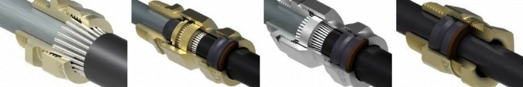
Hazardous Area Cable Glands
Each cable gland type has sub-sets:
e.g.
E1W = E1W cable glands with IP66 seals on inner and outer cable sheath
E2W = As E1W type cable gland but E2W cable glands are with an electrical bond for a metallic inner sheath (e.g. lead sheathed cable)
Cable glands are often named to describe their function, e.g. E1FX, E1FW.
Cable Gland Size
The cable gland size must be selected to match the cable size.
IEC 60079-14:10.2 Selection of Cable Glands
The cable gland shall be selected to match the cable diameter. The use of sealing tape, heat shrink tube or other materials is not permitted to make the cable fit to the cable gland.
Hazardous Area Protection Method
Ex d / Ex e / Ex nR
The protection method MUST meet or exceed the protection level of the equipment that the cable gland is connected to. This is a requirement of IEC 60079-14: Clause 10.2.
Extract from Table 10 of IEC 60079-14
| Explosion Protection Technique For The Equipment |
Cable Gland Protection Technique |
| Ex d |
Ex e |
Ex nR |
| Ex d |
X |
|
|
| Ex e |
X |
X |
|
| Ex nR |
X |
X |
X |
| Ex i Group II |
X |
X |
X |
| Ex p |
X |
X |
X |
When to use a barrier gland
Barrier glands are always certified Ex d, but can be used in an Ex e environment.
How do you know when to use them?
When to Use a Barrier Gland – Ex d
A barrier gland MUST be used in an Ex d environment unless the cables:-
- Circular and compact
- Have an extruded bedding or sheath
- Use non-hygroscopic fillers

Old Rules in IEC 60079-14

New Rules – Barrier Gland Ex d
The cable entry system shall comply with one of the following:
a) Cable glands sealed with setting compound (barrier cable glands)
b) Cables and glands meeting all of the following:
– cable glands comply with IEC 60079-1 and are certified as equipment
– cables used comply with 9.3.2(a)
– the connected cable is at least 3 m in length;
c) indirect cable entry using combination of flameproof enclosure with a bushing and increased safety terminal box;
d) mineral-insulated metal-sheathed cable with or without plastic outer covering with appropriate flameproof cable gland complying with IEC 60079-1;
e) flameproof sealing device (for example a sealing chamber) specified in the equipment
documentation or complying with IEC 60079-1 and employing a cable gland appropriate to the cables used. The sealing device shall incorporate compound or other appropriate seals which permit stopping around individual cores.
The sealing device shall be fitted at the point of entry of cables to the equipment.
The cable entry system shall comply with one of the following:
a) Cable glands sealed with setting compound (barrier cable glands)
b) Cables and glands meeting all of the following:
– cable glands comply with IEC 60079-1
– cables used comply with 9.3.2(a)
(They shall be circular and compact. Any bedding or sheath shall be extruded. Fillers, if any, shall be non- Hygroscopic)
– the connected cable is at least 3 m in length
The HSE in the UK has issued a bulletin stating that installations to the ‘new rules’ may not be safe and has suggested that the old flowchart used.
If in doubt USE A BARRIER GLAND.
➡ CMP PX2K-REX RapidEx – Revolutionary Sealing Solution for Barrier Cable Glands

Barrier Glands
When to use a Barrier Gland – Ex d
Barrier glands should also be used:-
- In Ex e applications when there is a risk of gas migrating down a cable. (IEC Ex 60079-14 clause 9.3.2)
- In Ex nR applications where the cable is not sealed. (IEC Ex 60079-14 clause 10.8)
Modern ‘liquid resin’ barrier glands are easy to install.

Environmental Conditions
Four main areas to cover in this section:
• Temperature
• Ingress protection (IP)
• Dissimilar metals
• Corrosive environments
Temperature
- Cable glands do not have a ‘T’ rating
- Under existing IEC Ex rules, the temperature rating of a cable gland does not have to include the thread sealing gasket
- Responsible cable gland manufacturers test and certify their cable glands and sealing gaskets together
Ingress Protection (IP)
A sealing gasket may be needed to maintain the IP rating of the assembly.
(IEC Ex 60079-14 clause 10.2)
Check that the thread sealing washer has been tested with the cable gland as part of the certification process. (The IP rating will be shown on the IEC Ex certificate.)
Dissimilar Metals
- Ideally the cable gland should be made of the same material as the equipment and the cable armour it is connected to
- For most equipment electroless nickel plated brass is the best option

Brass gland fitted to an aluminium enclosure

Superior Marine grade nickel plated brass gland fitted to an aluminium enclosure
Corrosive Environments
Corrosive environments may typically include:-
- Salt / salty water
- SO2
- NH3
For many corrosive environments a good quality nickel plated brass cable gland is the best choice
- Not all plating is equal
- Specify at least 10 microns of plating thickness
(The rules on plating thickness changed with the 2014 edition of IEC 60079-1. Clause 5.1 now allows a thickness greater than 8 microns.)

Not all electroless Nickel Plating is equal – Before & After Salt Spray Test
For highly corrosive environments the choices are either:-
- Stainless steel
- Specialist corrosion protected cable glands
Installation / Inspection Considerations
Choose cable glands that are:-
• Easy to install
• Don’t have parts that can get mixed up
• Don’t have loose parts
• Can be inspected easily
Further Reading

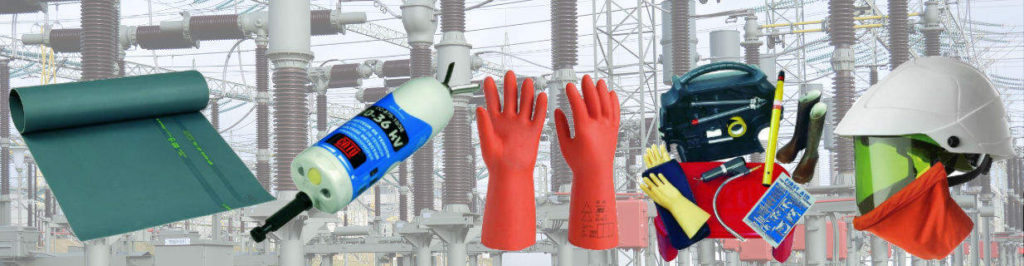
ELECTRICAL & PROCESS INSTRUMENTATION EQUIPMENT
FOR EXPLOSIVE ATMOSPHERES
Thorne & Derrick International, based in the UK, are Specialist Distributors of Hazardous Area & Explosion Proof Equipment with IECEx & ATEX Certifications to the onshore and offshore oil, gas, petrochemicals and process industries.
Key Product Categories: Control Panels | Plugs & Sockets | Isolators | Enclosures & Junction Boxes | Lighting | Control Stations | Motor Starters | Heat Trace Cables & Systems | Gas Detection & Detectors | Fire Detection & Detectors | Heat Detectors | Electrical Heating & Heaters
 Also Process Instrumentation Products: Ashcroft Pressure Gauges | ASCO Valves | Katronic Flow Meters | KROHNE Flow Meters | VEGA Level Sensors | Rotronic Temperature & Humidity Sensors | SIKA Pressure Gauges

Protecting Substations Against Flooded Ducts
Retrofitting a flooded substation
A flooded electrical substation. A run-down pump. And another switchgear failure.
Do you recognize the scenario? Would you like to avoid it?
Learn how to get it all right from the start.
Distribution network operators and maintenance contractors all over the world struggle against water and dust ingress in electrical assets such as substation basements and control rooms. Since humidity is often the cause of partial discharge activity, equipment damages, switchgear failures and costly power outages, they have a lot to win in keeping the basements dry. There are ways of sealing properly against water leakage through openings for cables and pipes using cable transits and thereby eliminate the risk.

Cable & Pipe Sealing Transits & Systems
1. Face the facts
To be honest, mastics, compounds and other traditional sealing products do not withstand the pressure of a high ground water table or the strain of the cable load. Neither do they seal between cables. Mastics may be cheap to buy, but the total cost of damages and outages actually makes them expensive. When the flood enters, you should call a provider of reliable cable sealing solutions.

2. Locate the leaks in the flooded substation
A professional sealing expert from Roxtec will meet you, survey the flooded site and establish an action plan. This specialist presents durable retrofit solutions for each opening, in line with requirements. Meanwhile, you will learn how to detect weak duct sealing methods – and to secure the openings before it is too late.

3. Get it all right
When you turn to experts, you get drawings, certificates and installation instructions and you often receive the seals within 48 hours. In addition, the experts provide onsite support and perform quality checks after installation. First class retrofit seals can be used in running water conditions and will still perform within 24 hours. Compare this to the normal curing time of ten days for mastics.

Further Roxtec Reading
Thorne & Derrick Specialist Electrical Distributor
Established since 1985, T&D distribute the most extensive range of LV, MV & HV Cable Jointing, Terminating, Pulling & Installation Equipment – contact us today for a competitive quotation.
Key Products : MV Joints & Terminations, Cable Cleats, Duct Seals, Cable Transits, Underground Cable Protection, Jointing Tools, Feeder Pillars, Cable Duct, Earthing & Lightning Protection, Electrical Safety, Cable Glands, Arc Flash Clothing Protection & Fusegear.
Distributors for : 3M, Pfisterer CONNEX, Nexans Euromold, Elastimold, Catu, Roxtec, Emtelle, Centriforce, Lucy Zodion, Alroc, Hivotec, Cembre, Prysmian, Ellis Patents, ABB & Furse.

Furseweld | The Furse System of Exothermic Welding
Furseweld
The Furse System of Exothermic Welding
Since 1893, Furse has provided world leading Earthing, Lightning and Electronic Systems protection solutions for electrical infrastructure, building services and LV MV HV substations.
FurseWELD exothermic welding is a cost efficient method of achieving high quality electrical connections.
FurseWELD is a simple, self-contained exothermic welding system that uses the high temperature reaction of powdered copper oxide and aluminium, within a mould, to form permanent electrical connections.
Exothermic welded connections are accepted according to the 11kV and 33kV substation earthing design and construction manuals by most UK DNO’s, including UK Power Networks (UKPN) – for instance earth welding copper to copper tape connections and copper tape to stranded cable earthing connections.
Typical Exothermic Welding Applications
- Earthing for power plants and high voltage substations (11kV-33kV)
- Telecommunications
- Transmission and power distribution lines
- Cathodic protection
- Rail connections

Exothermic Wedling Using the FurseWELD System
FurseWELD Earth System Benefits
- Requires no external power or heat source
- Creates high quality electrical connections
- Completely portable
- Can be used safely with minimum training
- Cost effective exothermic welding
- Can be used for over 45 standard connection configurations
FurseWELD Earth Connection Advantages
- Tolerant to repeated fault currents
- Highly conductive
- Does not loosen
- Excellent corrosion resistance
FurseWELD Exothermic Welding – contact T&D for Training & Certification Courses


FurseWELD connections have at least twice the cross-sectional area of the copper conductors being joined or welded, and an equivalent or greater current carrying capacity. Corrosion resistance is exceptional due to the very high copper content (> 90%) of the alloy.

Typical FurseWELD Applications
- Bar to Bar
- Bar to Earth Rod
- Cable to Bar
- Cable to Cable
- Cable to Earth Rod
- Exothermic Moulds & Joints
FurseWELD is suitable for earth rod connections to copperbond, solid copper and stainless steel earth rods – threaded porttion of copperbond earth rods must be removed prior to FurseWELD application.
Welding procedure
- Position the cleaned conductors in the mould after ensuring the mould is dry by pre-heating or making a test joint.
- Lock the mould with the handle clamp; if the mould does not close properly adjust the tension by removing the split pin and turning the eye bolt accordingly. Insert the steel disc into the mould crucible, ensuring it is centred over the tap hole.
- Pour the welding powder into the crucible; the starting powder is retained in the underside of the cartridge and identified by a red cap.
- Spread the starting powder evenly over the welding powder, placing a small amount on the top edge of the mould for easy ignition.
- Close the cover and ignite the starting powder with the flint gun; pull the gun away immediately to prevent fouling the flint. Wait a few seconds to allow the metal to solidify before opening the mould. Remove all slag and dust before making the next weld.
FurseWELD Exothermic Welding Moulds
FurseWELD system of exothermic welding uses moulds to contain the exothermic reaction that creates safe and robust connections. Different types of FurseWELD moulds are available, whose use depends on the requirements of the project.
- Graphite Moulds – Marketleading FurseWELD graphite moulds are extremely robust and capable of creating over 75 connections each.
- Mini-Moulds – FurseWELD mini-moulds are a cost effective alternative to full sized moulds, especially where lower numbers of connections are required. They are smaller overall, less robust and therefore lower priced. Care is required in order to achieve similar service lives to full sized moulds.
- Sureshot – the FurseWELD Sureshot system is a single use ceramic mould supplied complete with retaining disc and powders – It has been designed for use in applications where only a few exothermic welding connections are required.
FurseWELD – How to make a FurseWELD Joint Connection
1. Locate the copper conductors to be joined in the FurseWELD cavity and close the mould.
2. Locate the steel retaining disc in the base of the crucible, pour in the weld powder followed by the starting powder. Ignite starting powder with a spark gun.
3. The exothermic reaction reduces the weld powder to molten copper alloy which melts the retaining disc and flows into the weld cavity where it partially melts the conductors
4. The molten copper allow cools to leave a fusion weld of great mechanical and electrical integrity.


FURSEWELD TOOLS / ACCESSORIES

Furseweld Exothermic Welding Tools & Accessories
- Handle Clamp
- Flint Gun
- Toolkits including cable or tape cleaning brush, mould cleaning brush & mould scraping tool
- Gas torch (to preheat the mould)
- Optional toolbox & heat resistant mould jacket
Potential Hazards
As with all forms of welding the potential hazards are:
- Accidental contact with hot work.
- Spatter of molten metal.
- Eye irritation.
- Throat/chest irritation.
Frequently Asked Questions About Exothermic Welding
Could you tell me how many welds can be completed before replacement of the mould is required?
With regards to the Exothermic Welding Mould, the mould should be good for 40-50 joints at a minimum (they could easily do a lot more if they are maintained and used correctly).
Are the earth welding products classed or recognised as “explosives”, and should they be stored in a secure metal box and labelled as explosives?
- FurseWELD materials must be stored in a dry and secure place
- Only take onto site, sufficient materials to give continuity of work
- Fully discuss the operation with the client including site fire precautions. Note: A permit to work system may be required before work can be done
- Wear all of the above listed personal protective equipment and any other equipment which may be required for the job in hand
- Do not use flame or heat near flammable substances or atmospheres; this will include the following: paints, solvents, oils, petroleum, diesel, gasses, paper, rags
What are the training and competency assessments requirements and how often should this training be reviewed, refreshed or renewed?
Furse can offer Exothermic Welding Training and will supply a certificate at the end to show that the user has successfully completed a course of instruction and demonstrated competence in the process. This certificate will last for 4 years – contact Thorne & Derrick for further information.
PPE Requirements?

Safety Goggles & Heat Resistant Gloves
The following should always be worn:
- Safety Goggles
- Heat Resistant Gloves (welders gloves)
- Safety Boots (for site use)
- Safety Helmet (for site use)
- Fire Bucket or Extinguisher (if working near flammable materials)
In addition to the above, other equipment may be required dependent upon the location of and the nature of the job. This may include:
- Fire bucket/extinguisher (if working near flammable materials).
- Heat resistant board (to contain spillage or protect surfaces).
Further Reading
THORNE & DERRICK
Thorne & Derrick are national distributors of LV, MV & HV Cable Installation, Jointing, Substation & Electrical Equipment – servicing businesses involved in cabling, jointing, substation, earthing, overhead line and electrical construction at LV, 11kV, 33kV, 66kV and EHV. Supplying a complete range of power cable accessories to support the installation and maintenance of low/medium and high voltage power systems:
- Slip-on Cable Terminations
- Cold-shrink Cable Terminations
- Heat-shrink Cable Terminations
- Cable Joints – Heat & Cold-shrink
- Separable Connectors (Euromold)
- Surge Arresters & Switchgear/Transformer Bushings
Key Product Categories: Duct Seals | Cable Cleats | Cable Glands | Electrical Safety | Arc Flash Protection | Cable Jointing Tools | Cable Pulling | Earthing | Feeder Pillars | Cable Joints LV | Joints & Terminations MV HV


GRP Feeder Pillars – A Short Guide To For Site Installation
GRP Feeder Pillars
The following article has been written to provide guidance to civil engineering and groundworks contractors for the installation of GRP feeder pillars used to provide low voltage electrical power distribution.
Step 1. Concrete base must be clean and free from any earth, stones or any other debris which will prevent the feeder pillar or kiosk sitting flat on its base – it is recommend that a stepped base be cast for feeder pillasr where the inner level is 50mm above the base flange, so as to prevent water ingress into the kiosk.
Step 2. Orientation of the feeder pillar is to be agreed before the pillar is positioned on to its base. It is good practice to have the pillar sitting in the middle of the base with an equal amount of slab around the pillar. The feeder pillar can be manoeuvred using a jemmy bar from inside or outside the unit; care is to be taken so as not to damage the gel surface.
Step 3. Check for an equidistant gap between the door and door frame and that the doors operate freely. The doors can be adjusted by placing shims between the base and the feeder pillar directly in line with the door hinges; these shims should be of non corrosive metal, plastic or even GRP.
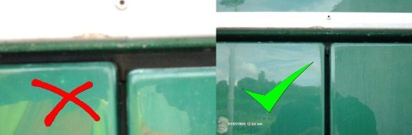
Check for an equidistant gap between the door and door frame and that the doors operate freely
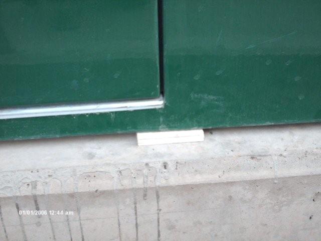
Packing shim
Step 4. Ensure that walls of the pillar are straight and are not “bowing”.
Step 5. Drill 12mm holes in the GRP base flange of the pillar at approximately one metre intervals using a battery drill (some feeder pillars may have already been pre drilled).
Step 6. Various anchor bolts can be used to pin the feeder pillars down depending on site specification – it is recommended to use an M 10 x 75mm sleeve anchor expansion bolt as standard. Size and depth of the hole should be in accordance with the fixing being used.
Step 7. Drill should be used at right angle to the concrete base; however, the holes can be drilled at an angle where a plywood board may prevent the drill from operating at 90 degrees.
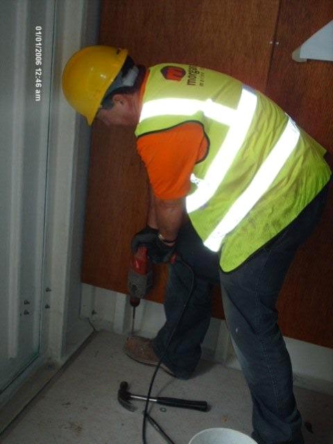
Drill should be used at right angle to the concrete base
Step 8. Re-check door levels after bolting down the pillar.
Step 9. Apply a bead of silicon to fill the gap between the feeder pillar and concrete base. This cannot be relied upon to provide a water tight seal; it is used for cosmetic purpose and will also prevent any concrete screed from running down the face of the concrete base.
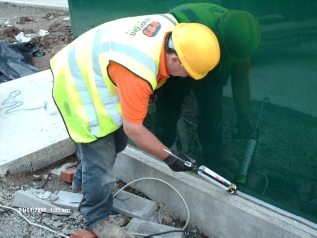
Apply a bead of silicon to fill the gap between the kiosk and concrete
Step 10. Remove the lifting eyes and seal holes with the plastic bungs provided.

Feeder Pillars – Galvanised Steel | Stainless Steel | Cast Iron | GRP
Thorne & Derrick
T&D are Specialist Distributors to UK Distribution Network Operators (DNO’s), NERS Registered Service Providers, ICP’s and HV Jointing Contractors of an extensive range of LV, MV & HV Jointing, Earthing, Substation & Electrical Eqpt – this includes 11kV/33kV/66kV joints, terminations and connectors for both DNO and private network applications.
Contact our UK Power Team for competitive quotations, fast delivery from stock and technical support or training on all LV-HV products.
Key Product Categories: Duct Seals | Cable Cleats | Cable Glands | Electrical Safety | Arc Flash Protection | Cable Jointing Tools | Cable Pulling | Earthing | Feeder Pillars | Cable Joints LV | Joints & Terminations MV HV
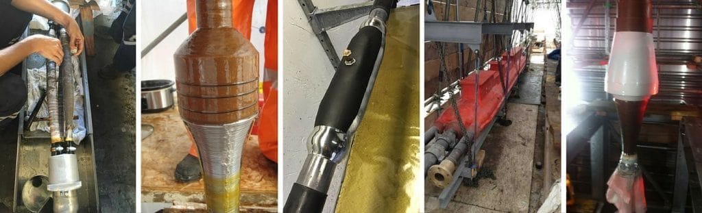
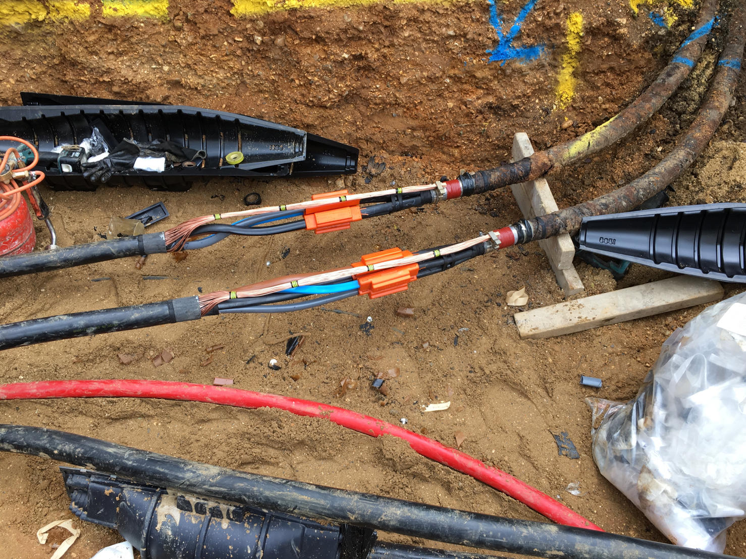
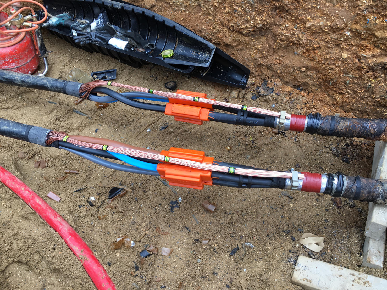
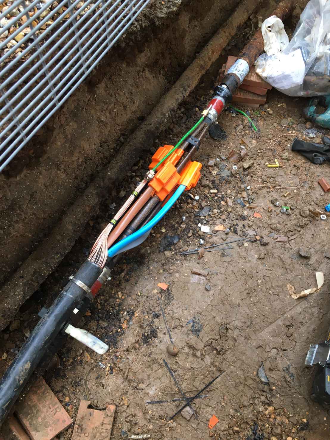
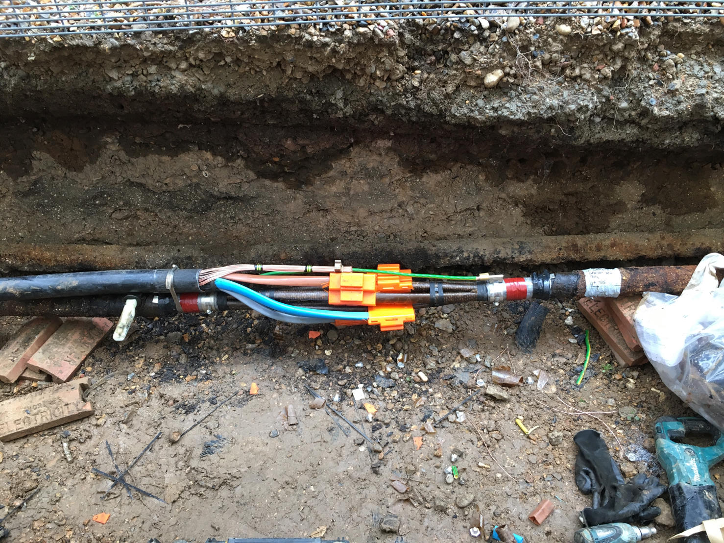
- Application: PILC Cable Joints & LV Switchgear Connections
- Cable Type: PILC Cable Joints
- Cable Jointer: Lee Richards Self Employed Cable Jointer at LR Power Services. SSE Authorised, PILC, Consac, PICAS. 33kV Pfisterer, LV-11kV. 11kV Lovink
PILC Cable Joints

Cable Jointing Contractors
Here is Lee Richards (LR Power Services) undertaking a switchgear change during a shut down involving the following LV Joints: 1 x 4c 300sqmm PILC Breech Joint, 2 x 4c 300sqmm PILC Straight Joints and 1 x 4c 185sqmm PILC Straight Joint.
Lee is a respected and acknowledged Competent Jointer – his skill set includes completion of the SSE LV HV Jointer Training program and also current 33kV Prysmian Straight Joint and 33kV Nexans Euromold T Connectors tickets.

JOINTERS BLOG
Subscribe now to our POWER NEWSLETTER– a monthly email circulation packed with news, projects, videos, technical tips, training information, promotions, webinars, career opportunities and white papers.
Includes access to our popular JOINTERS BLOG with contributions from utility professionals, linesmen and cable jointers working on MV HV EHV cables and overhead lines typically at 11kV, 33kV, 66kV and up to 132kV.
15,000+ Subscribers. ➡