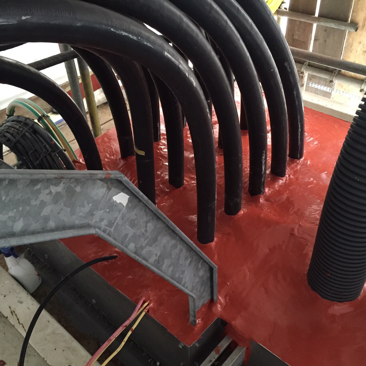
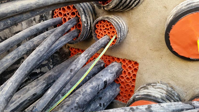
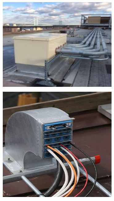
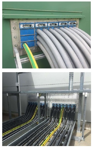
CSD Technical Services have been involved in a key renewable energy project since 2020, whereby they have been specified for duct seal entries across a huge onshore substation site. The sealing of three additional 250mm cable entries, each containing a 1x120mm cable, was requested by the client. As with other areas of the site, the NOFIRNO Duct Seal System, manufactured by CSD Sealing Systems, was used to provide a water and gastight seal.
Sealing Challenges
There were no major challenges encountered as the NOFIRNO Duct Seal System is the ideal solution for vertical ducts. This is due to the fact the insert sleeves cling to the cables and ducting without sliding down and falling out of the penetration. The high adhesion and viscosity of the NOFIRNO Sealant means it will also not run down the duct when applied.
Outcome Using NOFIRNO
The NOFIRNO multi-sleeves were installed to provide cable separation and a firm backing for the NOFIRNO Sealant layer. The cable entries which were exposed to the elements are now watertight.
Water and gastight sealing protection of cable duct and building entry points.
NOFIRNO Sealant
The NOFIRNO Duct Seal System comprises of two components; 60mm rubber NOFIRNO multi-sleeves which provide cable support, ensure cable separation, and provide a backing for the second component which is a 20mm layer of NOFIRNO Sealant. To ensure the NOFIRNO Sealant adheres correctly, the areas in where the sealant is to be applied should be clean and dry before application i.e., the cables and any frames and structures.
The NOFIRNO multi-sleeves are then installed providing cable separation and a firm backing for the NOFIRNO Sealant layer. The system will provide a water and gastight seal to certified levels of 2.5 bar and has been shown to provide protection for a period of at least 50 years.
Key Benefits of Sealing Cables
• Tested to prove no deterioration in performance for more than 50 years
• Provides flood protection and prevents water and gas ingress – pressure rated up to 2.5 from the front and back of the seal
• Quick and easy to install to install
• Easy re-entry for adding, removing or replacing cables
Specialist Distributors to the UK and international Offshore Wind & Renewable industry to provide safe and reliable LV HV Electrical Cable & Power Distribution Systems up to 66kV – we are highly customer responsive and absolutely committed to providing a world-class service. Contact our UK Power Team for competitive quotations, fast delivery from stock and technical support or training on all LV-HV products.
Stockists & Suppliers | UK & International Projects
8.10.2024
By Chris Dodds | Sales & Marketing Manager at Thorne & Derrick International
“Bringing People Together”
A brilliant bullet from Paul Frankland’s (Operations Director at NEPIC) super slide-deck presented to us this morning at the Wilton Centre, the premier science park in the North East of England adjacent to Wilton International and sitting in the heart of the North East of England Process Industry Cluster (NEPIC).
The NEPIC Cluster is the largest industrial concentration of chemical, pharmaceutical and process companies in the UK, and the second largest in Europe.
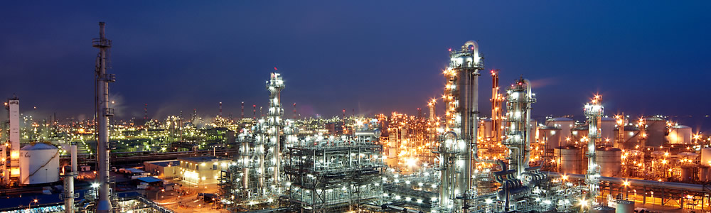
Paul and Joanne Fryett (CEO at NEPIC) hosted Thorne & Derrick and an international delegation from 3M Electrical to discuss Energy Transition developments and opportunities within the Cluster involving Net Zero. NEPIC have now extended further support for Thorne & Derrick’s business growth strategy in the clean energy, low carbon and hydrogen sectors.
The NEPIC Presentation informed us all about the energy project pipeline on Teesside with major companies including BP, Equinor, Huntsman Corporation, SABIC, PD Ports, MGT Teesside and px Group.
Michael Kendall (Business Solutions Manager – Tees Valley Combined Authority) then underlined the central role of Teesside in UK plc’s economic growth drive which is strategically aligned with the UK’s Net Zero Strategy. The TVCA secures investment and creates jobs; it is home to ReNew ELP, Alpek, Conoco Phillips, EDF Energy, Mitsubishi Chemical and global renewables giant JDR Cable Systems.
We then all benefitted from excellent electrical power and utility insights provided by Gillian Baker (Head of Commercial New Business – Sembcorp).
Sembcorp supply the high voltage power (66kV/11kV) to Wilton International clients via their owned and operated on-site power station, substations and private wire electricity grid.
Our visit concluded with a Guided Tour of Wilton by Paul Frankland that emphasised the sheer scale of business opportunity, national leadership and centre of excellence our region provides for the the future of decarbonised power.
Hazardous Area Zones & High Voltage Systems
Thorne & Derrick International, based in the North East of England, are leading UK Specialist Distributors of products to guarantee personal safety, site efficiency and plant reliability in Harsh, High Voltage & Hazardous Areas.
Our diversity is our strength, from providing legacy asset management solutions for aging electrical infrastructure to the delivery of high voltage cable connection products to repair or energise networks from 600V to 66kV.
We can competently specify and competitively supply an extensive range of Hazardous Area Equipment (ATEX & IECEx) to provide Power, Heating & Lighting to the Explosive Atmospheres industries – this includes LV HV Cables, Accessories, Jointing, Substation & Electrical Eqpt.
We are 3M Electrical Distributor for the UK and can be trusted to specify and supply from the largest stocks in the UK and EU products utilising Scotchcast Resin and Cold Shrink Technologies for the installation, jointing and termination of cables from Low to High Voltage.
We are a firmly established vendor and high-value added member of the Cluster supply-chain – we provide world-class customer support including Design Services for Trace Heating & Lighting Systems for Zone 1/2 (21/22) hazardous area applications from our partners Eltherm and Raytec.
Sealing Cables & Protecting Assets |The CSD Sealing System range of DSEAR compliant NOFIRNO products are extensively specified for the prevention of water ingress, gas migration and fire spread in industrial and potentially explosive atmospheres including hazardous area Zones with ATEX designation including Zone 1 & 2 Flammable Gas.
Decarbonising the Teesside Cluster
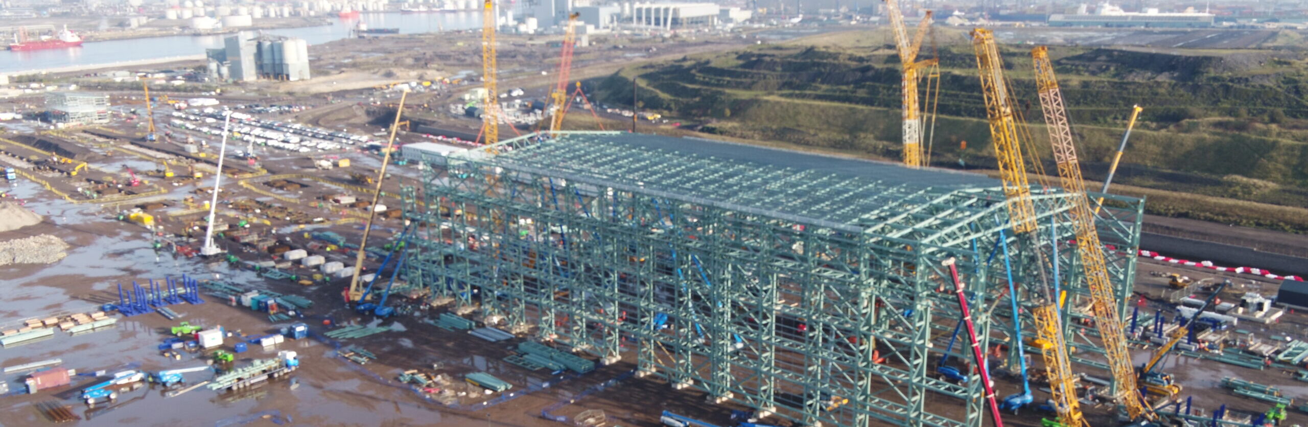
Last weeks government green-lighting of the Net Zero Teesside project, a £4billion investment which will establish the world’s first industrial-scale Carbon Capture, Utilisation and Storage (CCUS) facility at Teesworks was accompanied by confirmation from the Department for Energy Security and Net Zero of £21.7 billion of funding to establish the UK as an early leader in 2 growing global sectors, CCUS and Hydrogen. This reignition of the UK industrial heartlands to be delivered by investment in projects and the energy-tech of the future further enhances Teesside’s position at the centre of the Decarbonisation universe.
Teesworks |The UK’s largest Freeport Tax Zone, most connected industrial zone and home to diverse, sustainable and low-carbon activity. In 2023, SeAH Wind announced a £650m investment in a monopile manufacturing facility at South Bank Teesworks to support a contract with Vattenfall to supply all the wind turbine monopiles for its Norfolk Vanguard Project. This commitment to Teesside positions SeAH Wind as the UK’s leading Foundation Manufacturer and ensures the UK is at the forefront of developing offshore wind globally.
Net Zero Teesside
NZT is a collection of industrial, power and hydrogen businesses which aim to decarbonize their operations through the deployment of CCUS.
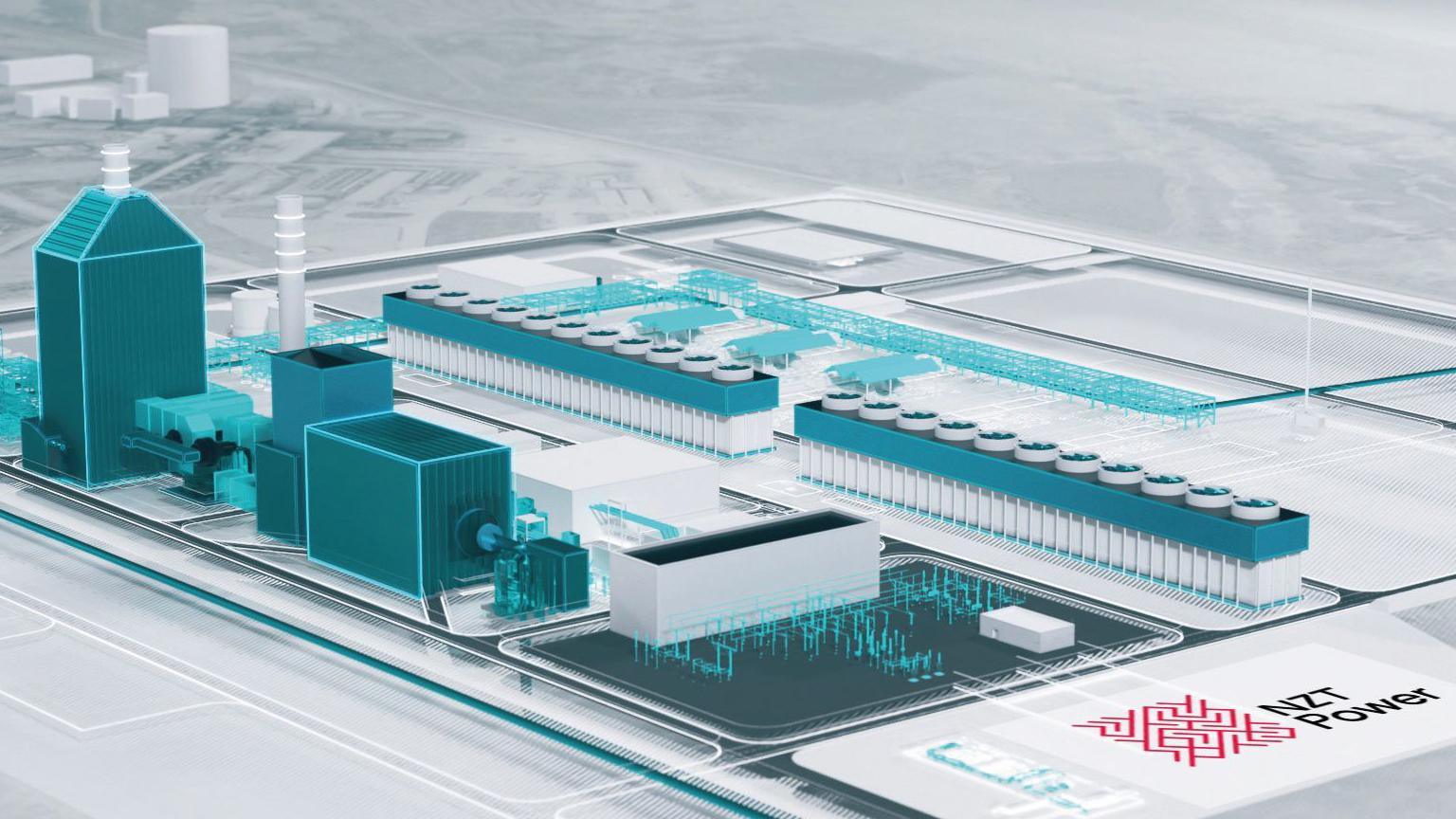
NZT Power is a first-of-a-kind fully integrated gas-fired power and carbon capture project and a key driving force behind plans to make Teesside the UK’s first decarbonized industrial cluster.
NZT Power’s proposed combined cycle gas turbine electricity generating station will have an electrical output of up to 860 megawatts (MW) of low carbon electricity, enough to power up to 1.3m homes per year.
NZT | The UK’s First Decarbonised Industrial Cluster
A Sustainable Future for our Energy & for our Business
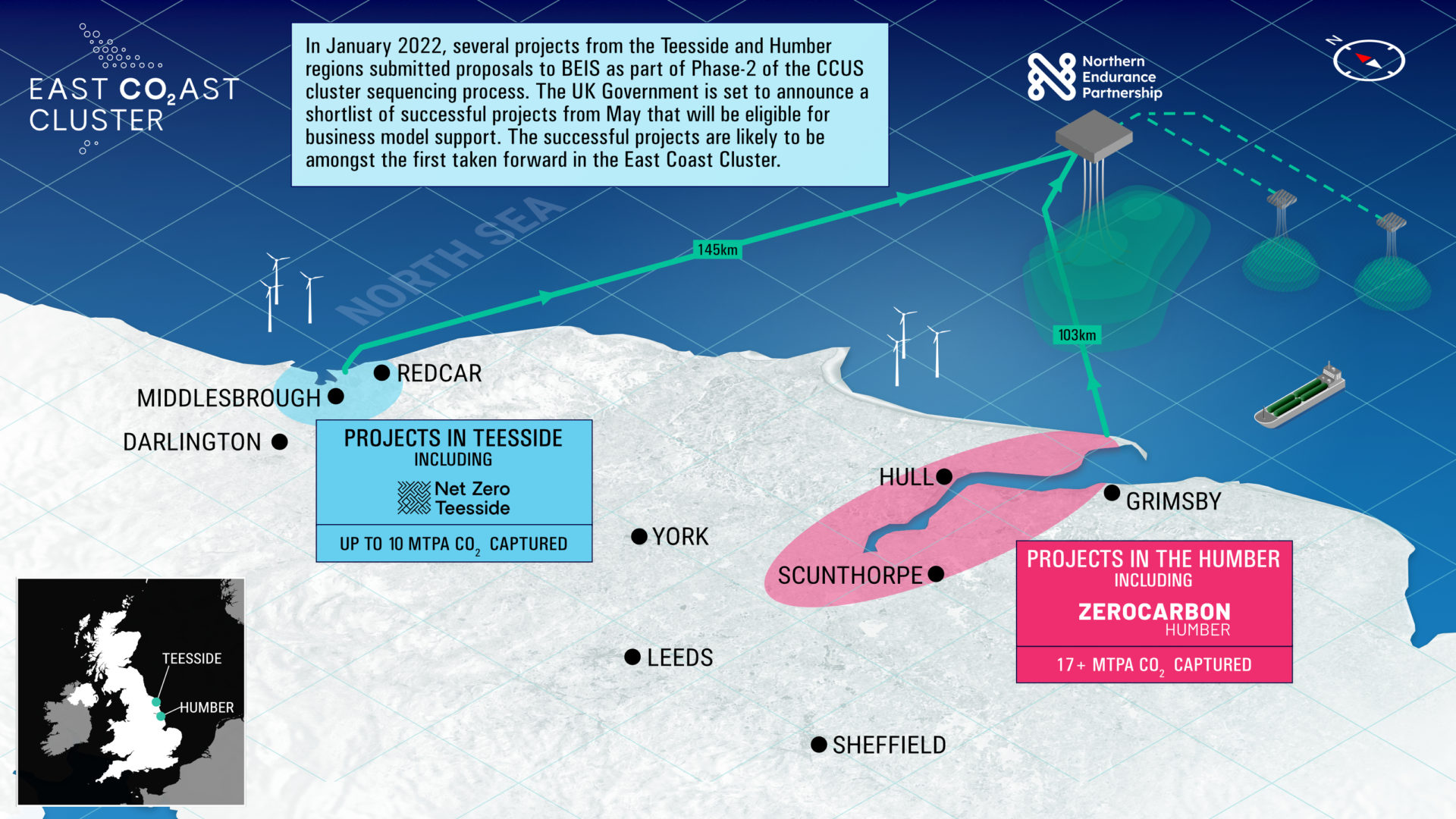
Our NEPIC Membership has positioned Thorne & Derrick alongside a cluster of businesses dedicated to the decarbonisation of industrial operations through the deployment of CCUS – we are working closely with EPC’s and contractors to specify and supply compliant critical equipment to build and operate the infrastructure required to transport CO2 from emitters in the Teesside and Humber regions to a secure offshore carbon store beneath the North Sea via the East Coast Cluster and the Northern Endurance Partnership.
The East Coast Cluster Decarbonising Industry
Northern Endurance Partnership | NEP is a CO2. transportation and storage company which will deliver the onshore and offshore infrastructure needed to capture carbon from emitters across Teesside and the Humber and transport to offshore storage in the Endurance store in the southern North Sea. In October 2021, The NEP’s East Coast Cluster, which includes Net Zero Teesside, was selected as a priority cluster in phase-1 of the UK Government’s CCUS cluster sequencing process. Endurance, a saline aquifer, has the capacity to store 450m tonnes of CO2. Other potential stores nearby take potential storage capacity to around 1 billion tonnes.
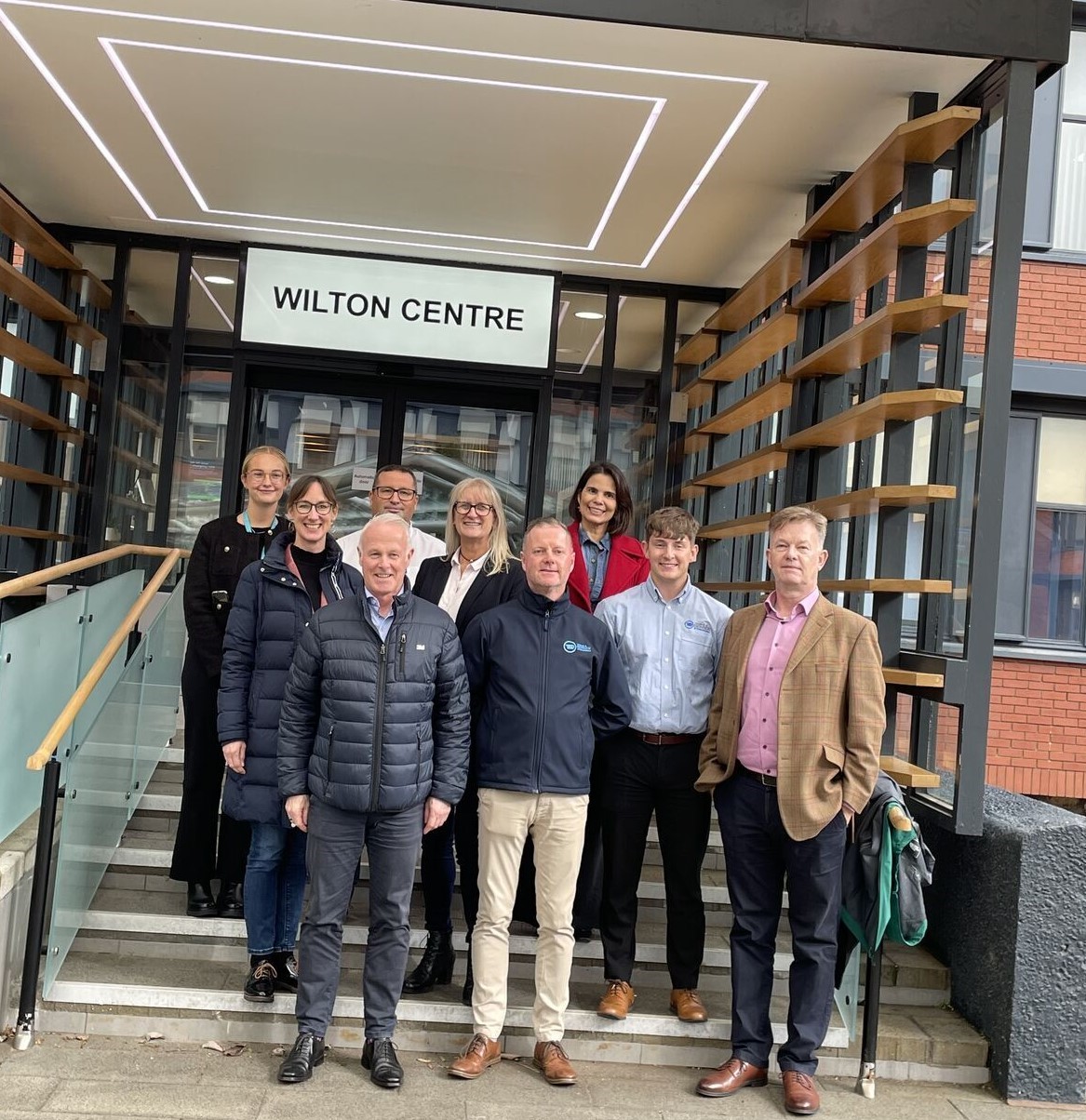
Pictured | Charlotte Fletcher (Project Manager Pharma-Sector NEPIC) Tanja Schroeder (Area Director EMEA 3M Electrical), Andy Townsend (Specification Manager C&I 3M Electrical UK), Paul Frankland (Operations Director NEPIC), Jenny Swindells (Regional Division Leader 3M Electrical Northern Europe), Chris Dodds (Sales Marketing Manager T&D), Monica Barros (General Business Director 3M Electrical ), Carl Cox (Sales Engineer T&D) and Richard Derrick (Managing Director T&D).
T&D are Specialist Distributors to the Process Industries – this includes the fine and speciality chemicals, petrochemicals, pharmaceuticals and polymers manufacturing sectors.
We supply and support businesses working on the design, construction and maintenance of UK, European and international projects.
Based in the UK, we are highly customer responsive and absolutely committed to providing a world-class service.
Since 1985, we have provided expert technical support and express delivery from extensive UK stocks to world-wide destinations.
3M Cold Shrink |This advanced Cold Shrink material technology has been developed into a comprehensive range of Cable Accessories to seal, joint, abandon, insulate and terminate cables from 600V to 66kV. Superior reliability, easy to install, and safe for use in Potentially Explosive Atmospheres.
Arc 4 Rated Switch Suit
Wins Prestigious Industry Award
Thorne & Derrick is proud to announce that the Arc 4 Rated Switch Suit, developed by ProGARM a leading manufacturer of arc flash clothing, using the cutting-edge PYRAD® Technology by GORE-TEX LABS, has recently won the prestigious Fibre, Fabric & Materials Award at the Professional Clothing Industry Association Worldwide Ltd Awards 2024 (PCIAW®). This recognition highlights innovations that push the boundaries of performance, protection, functionality, and comfort in professional clothing.
The Arc 4 Switch Suit sets a new standard for safety and comfort in Arc Protection.
Thanks to PYRAD® Technology by GORE-TEX LABS, the switching suit delivers Class 2 Arc Flash Protection in a single-ply textile, offering superior safety without sacrificing freedom of movement. Unlike traditional multi-layer, bulky fabrics that can be heavy and restrictive, this thin, lightweight design ensures maximum protection against arc flash incidents without compromising on comfort.
This ground-breaking product is a testament to the power of collaboration, combining ProGARM’s expert craftsmanship with the innovative GORE-TEX LABS technology to deliver a truly exceptional product to market.
The Arc 4 Switch Suit is now setting a new benchmark in the world of professional arc flash protective clothing. Stay tuned for more updates as we continue to push the boundaries of innovation in this field.
By Jason Hood, Global Segment Manager – Infrastructure Roxtec International AB
Abstract
With recent reports indicating an increased threat of extreme weather related events and rising sea levels due to climate change, critical infrastructure is expected to become more threatened by water ingress and flooding. For communication infrastructure, including data centers, it is critical to maintain operational reliability and reduce the risk of downtime.
Specifically, data centers must remain operational as downtime caused by any failure is expensive and uptime is critical. Flooding and water ingress remain a threat in extreme weather related events, but even in less extreme circumstances, water can be a nuisance and lead to longer term failures or decreased operational reliability.
Certain design considerations can be followed that will mitigate water ingress and reduce the risk of downtime.
With projected climate change effects likely, adopting effective sealing designs of openings in data centers as a best practice could effectively mitigate risk and should be considered in data center hardening strategies.
Downtime in Data Centers
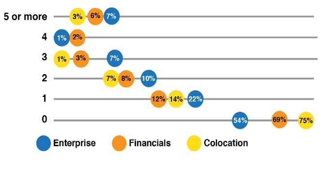
Downtime is a common concern for owners and operators of data centers. Although many precautions are taken, downtime still happens. The 2014 Data Center Industry Survey, conducted by the Uptime Institute, reported that between 25% and 46% of global data center operators and IT practitioners had experienced an outage that year.1
The same survey found that 3 – 7% had experienced an outage 5 times or more (Figure 1).
Figure 1 Number of Business-Impacting Outages. Source 2014 Data Center Industry Survey, Uptime Institute
Not only does downtime occur, it is also costly. The 2016 Cost of Data Center Outages, by the Ponemon Institute, reported that the average data center outage costs $740,357.2 This survey of 63 data centers from multiple sectors (e-commerce, financial, colocation, healthcare, etc.) provides a high estimate for downtime for an average size (14090 sq. ft.) data center.
Other surveys have reported an average hourly cost of downtime exceeding $300,000.3 Data center outages happen, and when they do, the costs are substantial. With increasing reliance on technology and data, the value of data will continue to increase, which translates into higher costs for downtime in the future.
Causes of Downtime
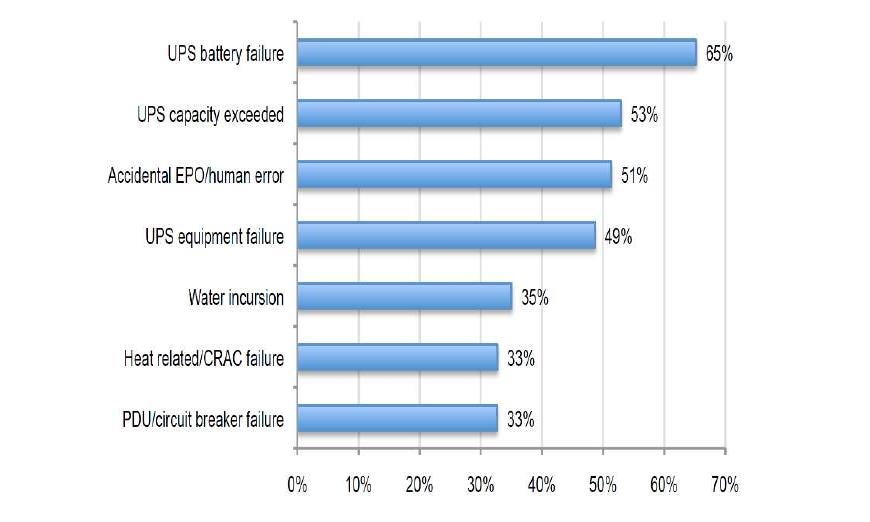
According to the National Survey on Data Center Outages by the Ponemon Institute, UPS battery failure (65%) was reported to be the most common cause of data center outages, with 3 of the top 4 causes UPS related.4 Human error was also reported as a common cause of outages (Figure 2).
Figure 2. Causes of downtime in Data Centers, Source National Survey On Data Center Outages, Ponemon
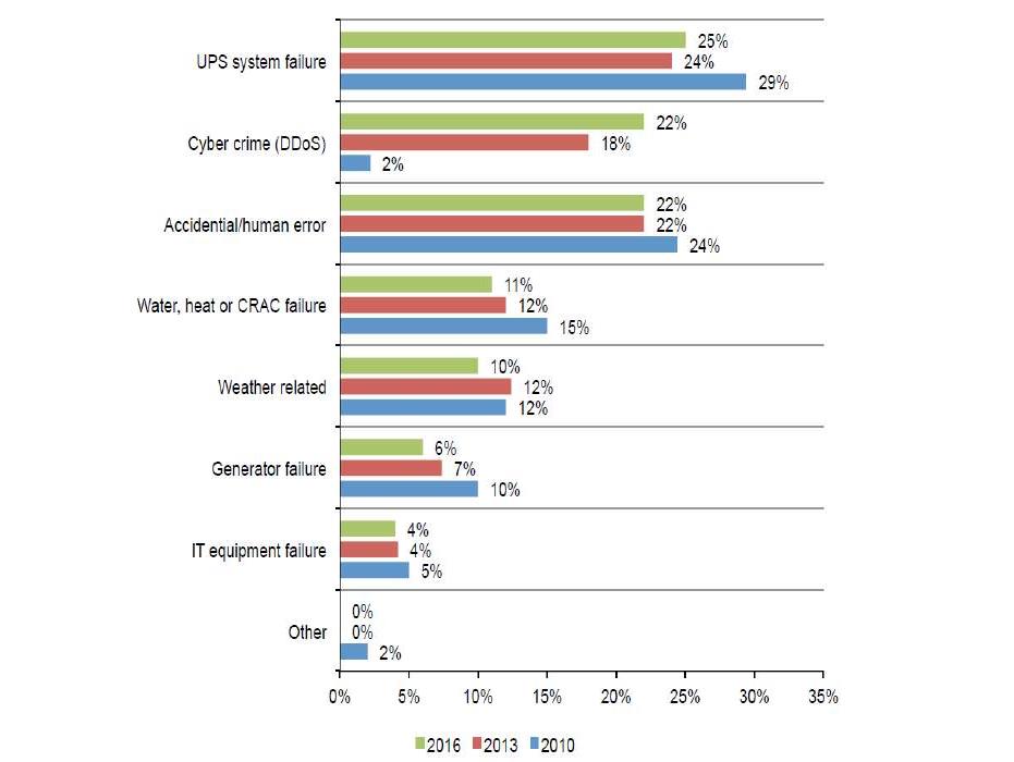
More recently, the 2016 Cost of Data Center Outages by the Ponemon Institute also reported UPS failure as the most common cause of data center outages.2
The same report also shows that human error is a primary cause (Figure 3).
Figure 3. Causes of downtime. Source 2016 Cost of Data Center Outages, Ponemon Institute
Both surveys show that human error is a common cause of data center outages, with a value as high as 51%. Other sources claim that human error is responsible for 70% of data center outages.5 From this data, it is clear that the most common causes of downtime are human error and mechanical issues.
However, weather related events are also cited as a cause of downtime. Although there are many types of weather related events, in some areas such as the United States, 90% of natural disasters involve flooding and cause more economic damage and loss of life and property than any other natural hazard.6
While weather related events might cause fewer outages, they do occur, and the effect can be significant. The damage caused by Hurricane Sandy in 2012 was extensive, with several data centers in lower Manhattan suffering from outages and subsequently pumping basements, generator rooms, and replacing damaged switchgear to restore power.7
During this event, internet downtime doubled and took almost 4 days to recover.8 Similarly, in 2015, the UK was battered with an extreme rainfall event that caused the river Aire to exceed its banks and reach a Vodafone facility in Leeds, causing an outage for several days.9
While these are extreme examples, flooding might be a more frequent occurrence than commonly believed. For example, in a 2015 survey conducted by Zenium, 60% of respondents stated that their data centers were located in low risk areas, with 40% of facilities in the UK considered to be flood resistant.10
However, this survey also discovered that 1 in 2 data centers had experienced disruption of service due to natural disasters, including seismic activity and flooding.
Even though data center downtime is most commonly associated with mechanical issues or human error, weather related events and flooding also cause downtime, and appropriate planning should be taken to mitigate possible risks.
Site Selection
During the site selection process, factors are evaluated such as environment, climate, reliability of power, fiber connectivity, labor pool, and financial impact (taxes, land incentives). While these are all important to evaluate, it is also important to evaluate the risk of natural disasters, considering risks such as seismic activity, extreme weather and flooding.11,12,13
Data Center location is arguably the best defense against natural disasters, where avoidance of areas that are prone to natural disasters is the strategy. There are industry standards to help guide site selection to mitigate risk of flooding. For example, TIA 942 provides guidelines based on the tier rating of the data center14(Table 1).
Table 1: Site Selection Guide for Tier Ratings. Source: TIA 942 Telecommunications Infrastructure Standard for Data Centers
TIER 1 (A1)
TIER 2 (A2)
TIER 3 (A3)
TIER 4 (A4)
Architectural
Site Selection
Proximity to flood hazard area as mapped on a federal Flood Hazard Boundary or Flood Insurance Rate Map
not required
not with the 50-year flood hazard area
No within 100-year flood hazard area and greater than 91m (300ft) from 50-year flood hazard area
Greater than 91m (300ft) from 100-year flood hazard area
Proximity to coastal or navigable inland waterways
not required
not required
Greater than 91m (300ft)
Greater than 0.8km (1/2 mile)
Tier ratings are defined by Uptime Institute and are described based on the infrastructure required to sustain operations.15 Under this classification system, a higher tier level indicates higher site availability, thus more stringent recommendations are warranted for higher tier rated data centers. In relation to potential flooding concerns, TIA 942 follows this logic by suggesting Tier 4 data centers be located greater than 300 ft. from the 100 year flood plain and greater than 1/2 mile from coastal or inland waterways.
For environmental risks, historical data for tornadoes, hurricanes, earthquakes, and flooding can be analyzed to help identify areas prone to natural disasters. Resources such as FEMA, USGS, NOAA, European Commission and European Environmental Agency provide helpful information that can be utilized for this purpose. Historical data, as well predicted trends, can help identify areas that are at high risk of natural disasters. This type of analysis can be critical for ensuring the right location is chosen to mitigate the most risk of natural disasters.
Site selection guidelines such as these are a common sense approach to mitigate risk of natural disasters, but the risk of some level of flooding might still be possible if additional factors aren’t considered.
Specifically, site specific factors such as elevation, slope, and water table should be evaluated as water intrusion and flooding can still occur even outside of a flood zone and under moderate to heavy rainfall periods, where water table levels can become a concern. ANSI/BICSI 002 – 2014 provides good recommendations for mitigating risks of water intrusion due to water table levels.16 This standard provides several good suggestions for choosing a site with a low water table and points out potential issues with locating data centers in low lying areas where water table levels and ground water can become a concern.
Important to note is that sections 5.7.1.6.3 (electrical) and 5.7.2.4.2 (communication) both recommend service entries to be underground. While this will mitigate risks of damage to overhead lines, underground distribution is not free from threats. The effects of heavy rainfall or a high water table can be exacerbated based on specific locations of vaults, ducts and electrical equipment. ANSI/BICSI 002 recognizes this and points out that utility ducts should be above the water table and to determine if utility maintenance holes can cause water ingress based on their location.
These standards and guidelines highlight the importance of a water mitigation strategy for data centers. Placing data centers in low risk areas is a great approach to risk mitigation due to natural disasters, but even under less onerous conditions, water can be a threat that data center owners, designers and operators must contend with to mitigate risk of downtime.
The Real Threat – Water
With proper site selection and design considerations, the risk of inundation by floodwaters can be minimized. However, water issues can exist even without extreme flooding conditions. Under moderate rainfall events, flooding of the data center might not occur, yet underground fiber and power distribution ducts and vaults can fill with water. Water inside vaults, while a nuisance, (water must be pumped out for maintenance), can also lead to high humidity levels and pose a threat to power distribution systems.
For example, common failure modes of switchgear include excessive temperature, partial discharge and humidity.17 Humidity can also increase partial discharge 18 and lead to bushing failures19 and long term insulation damage.20 IEEE Standard 493-1997, IEEE Recommended Practice for Design of Reliable Industrial and Commercial Power Systems, also documents the leading causes of switchgear failure from data collected through end-user surveys.21 Appendix E from this survey reports that the leading contributing cause to switchgear bus failure was exposure to moisture (30%) for insulated bus (Table 2).
While the exposure to moisture might not directly cause a failure, it facilitates deterioration of the insulation system, leading to a failure.22 This survey also shows that the “Exposure to Dust or Other Contaminants” was the second leading contributor to insulated bus failure. This is important to note as humidity in the presence of contaminants can also increase partial discharge.23
Table 2. Contributing Causes of Switchgear Bus Failure. (Source: Paoletti, G., & Baier, M. 2002)22
Switchgear Bus Failure Contributing Causes (%)
From IEEE Std 493-1997 Appendix E – Table XVIII
Ins. Bus
Bare Bus
Thermocycling
6.6
–
Mechanical Structure Failure
3.0
8.0
Mechanical Damage From Foreign Source
6.6
–
Shorting by Tools or Metal Objects
–
15.0
Shorting by Snakes, Birds, Rodents etc
3.0
–
Malfunction of Protective Relays
10.0
4.0
Improper Setting of Protective Device
–
4.0
Above Normal Ambient Temperature
3.0
–
Exposure to Chemicals or Solvents
3.0
15.0
Exposure to Moisture
30.0
15.0
Exposure to Dust or Other Contaminants
10.0
19.0
Exposure to Non-Electrical Fire or Burning
6.6
–
Obstruction of Ventilation
–
8.0
Normal Deterioration from Age
10.0
4.0
Severe Weather Condition
3.0
4.0
Testing Error
–
4.0
Total
94.8
100.0
The most common sources of humidity in substations are ambient air with high humidity, water leaks into substations, and water in cable trenches. 18 Water intrusion can cause instant issues such as short circuits.
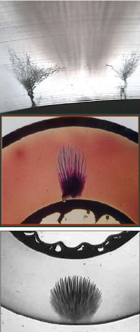
However, the effects of water and moisture can also be longer term, where the result can be insulation damage, corrosion, cable and equipment failure. One of the most commonly documented examples of longer term insulation damage from water on medium voltage cables is water treeing,24 which is a micro-crack propagation of degraded insulation (Figure 4).
These micro-cracks grow from stress points in the presence of water and can eventually lead to cable failure. These stress points are usually caused from manufacturing, transportation, pulling cables or service of cables.
Figure 4Examples of water trees in power cable insulation
While typical duct designs can ensure proper slope to direct water away from buildings and equipment, and vaults can be located above the water table, moisture can still be present inside vaults or ducts leading to and away from generators, switchgear, load banks and transformers.
This moisture can cause long term damage by facilitating insulation breakdown. Using cables optimized for these environments (e.g. TR-XLPE or LC) can reduce the risk, but not all cables failures are due to a breakdown in cable insulation.
Splices, cable terminations and cable joints are also a potential weak link as poor workmanship can lead to water ingress. The effects of water might not be immediate, and longer term, water in and around power distribution ducts and equipment can lead to premature cable failure.
Not only are power cables at risk, underground fiber optic cables are also threatened by moisture. While locating fiber optic cables underground removes inherent dangers of aerial placement, underground locations can be subjected to constant exposure to water inside ducts and vaults. The effects of moisture on fiber optic cables are well documented. 25,26,27,28 Some of the effects are signal attenuation due to water molecules embedding in micro-cracks, corrosion of connectors, signal loss and mechanical damage due to freezing.29
The effects of water can be minimized by using the correct type of cable. Typically, outdoor cables are designed to minimizes water penetration with the use of gel-filled tubes or waterswellable materials and are durable for harsh environments. As is the case with power cables, even with proper cable selection, the connections can be the weakest link. Using the right materials can minimize damage from moisture, but preventing water ingress and minimizing moisture where possible will provide the optimum protection of critical fiber optic infrastructure.
Climate Change
Even if proper site selection is achieved, will it be enough for the future? Climate change seems to be changing the rules and could potentially be the biggest threat to infrastructure. For example, in the UK, increased frequency of coastal, fluvial or pluvial flooding is expected to damage key ICT assets such as cables, masts, pylons, data centers, telephone exchanges, base stations or switching centers30 and increased flooding from all sources is the most significant risk to infrastructure.31
One of the most striking assessments highlighting the potential impact of climate change in the UK is a report by AEA compiled for DEFRA, the UK’s Department of Environment, Food and Rural Affairs. The report, Adapting the ICT Sector to the impacts of Climate Change, provides information related to underground and above ground infrastructure.32 The following points summarize some of the potential impacts of flooding:
Elements of infrastructure below ground are vulnerable to flooding, rising water tables, water ingress
Above ground – risks from precipitation, unstable ground, and humidity
Flooding of conduits, increased risk of flooding low-lying areas, access holes and underground facilities
In the US, the report Climate Change Impacts in the United States: The Third National Climate Assessment, U.S. Global Change Research Program reports similar information.33
Some of the key findings from the report are:
Infrastructure is being damaged by sea level rise, heavy downpours and extreme heat; damages are projected to increase with continued climate change
Over the past century, global average sea level has risen by 8 inches
Since 1992, sea level rise has been almost twice the rate observed over the last century
Sea level rise combined with coastal storms has increase the risk of erosion, storm surge damage, and flooding for coastal communities
Sea level is expected to increase 1 to 4 feet over this century
Coastal communities are at the greatest risk of storm surges and rising sea levels. Combined tide levels and rising sea levels is already contributing to chronic flooding in many US cities. Although it’s uncertain to know exactly how much sea level will rise in the future, moderate projections for sea rise predict nearly 490 communities in the U.S. will face chronic inundation by the end of the century.34 Additional scenarios show the number as 668 communities affected(Table 3).
Although most of the communities are small, larger cities will be affected such as Boston, New York, Miami, San Mateo and Newark. Of course, data centers are already located in these cities and undoubtedly, some could be at risk of flooding.
A recent paper, Lights Out: Climate Change Risk to Internet Infrastructure predicts that in 2030, with a 1ft rise in sea level, 235 data centers will be affected, as well as 771 POPs, 53 landing stations, and 42 IXPs.29
Table 3. Communities Facing Chronic Inundation As Sea Level Rises
Source: When Rising Seas Hit Home: Hard Choices Ahead for Hundreds of US Coastal Communities, Union of Concerned Scientists, July 2017
Low Scenario
Intermediate Scenario
High Scenario
% inundation
Present
2060
2100
2035
2060
2080
2100
2030
2045
2060
2070
2080
2090
2100
10-25%
44
63
112
64
103
133
195
75
109
152
165
208
226
240
25-50%
31
53
61
49
71
76
102
55
78
89
89
110
125
155
50-75%
12
42
58
37
50
74
59
30
44
71
69
71
81
76
≥75%
4
25
59
17
48
82
133
18
34
68
104
134
170
197
Total
91
183
290
167
272
365
489
178
265
360
427
523
600
668
The following are key points from this paper:
Sea level rise is projected to be 1 – 6 ft. by the year 2100
Under the most modest projection, 4,067 miles of fiber conduit will be under water
Internet infrastructure is designed to be weather and water resistant. They are not designed to be surrounded by or under water
Risks include physical damage at landing stations, physical damage via tidal inundations and corrosion leading to signal loss
Buried conduits will become submerged
Much of the infrastructure was deployed over the past 20 years and is aging, meaning that all seals and claddings are likely to vulnerable to damage if they are under water
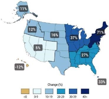
For new data centers, choosing to build outside of coastal areas seems like a safer option, but this option is not risk-free. Heavy rainfall events are increasing, which can also increase the risk of flooding. In the US, heavy downpours have increased in certain areas by as much as 71% (Figure 5).33
Figure 5 Changes in the amount of precipitation from very heavy events (1958-2012)
Source: Climate Change Impacts in the United States: The Third National Climate Assessment, U.S. Global Change Research Program. 2014. (Updated from Karl et. al 2009)35
Part of the reason for an increase in heavy downpours can be attributed to a warmer climate. For every 1 degree Celsius, there is 7% more moisture in the air.36 Based on the predicted global temperature rise of 3 – 5 degrees, heavy downpours could become even more frequent in the future, causing localized flooding and changing flood boundaries.
Even with reports such as these, in a recent survey of 867 data center operators and IT practitioners, only 14% reported that were taking climate change into considerations and “re-valuating site selection based on higher temperatures, increased flooding, or water scarcity.” 37
In the same survey, only 11% reported they are taking steps to mitigate increased flood risk. Although these numbers are low, they show that the threat of climate change and flooding is starting to be recognized and that some data center operators will implement a proactive water mitigation strategy.
Water Mitigation
Standards, such as ANSI/BICSI 002-2014 and TIA 942, do provide some guidelines for mitigating risk of water ingress. TIA 942 recommends a floor drain be placed in areas where risk of water ingress exists. It also states “the data center and all support equipment should be located above the highest expected floodwater levels. No critical electronic, mechanical or electrical equipment should be located in basement levels.”
In practical terms, this isn’t always the case. Even if equipment is at ground level, feeders often enter substations below ground and can become a pathway for water and humidity. In these areas, it is common to utilize pumps and dehumidifiers to remove water and humidity. These are all good design practices, but an often overlooked area is the utility ducts and distribution vaults as a water and humidity source.
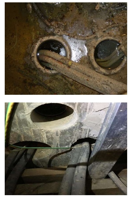
Commonly, specifications will point to some type of sealant for ducts, but many times, there is nothing installed and ducts are left open (Figure 6).
Figure 6. Unsealed ducts quickly fill with water and debris
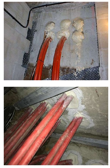
On-site remedies vary, but most commonly, foam or silicone is used (Figure 7). While these remedies will provide some level of protection, they are not effective long-term at stopping water pressure that builds up behind the seal.
Figure 7. Silicone and foam used to stop water ingress
In this scenario, ducts, vaults and maintenance holes fill with water and debris, where cables and equipment can be exposed to high levels of water and humidity. This is the highest risk scenario and is very common when construction specifications do not include details for sealing cable ducts and building entries.
In many cases, after a problem with water ingress has been discovered, some type of maintenance procedure is established to solve the problem.
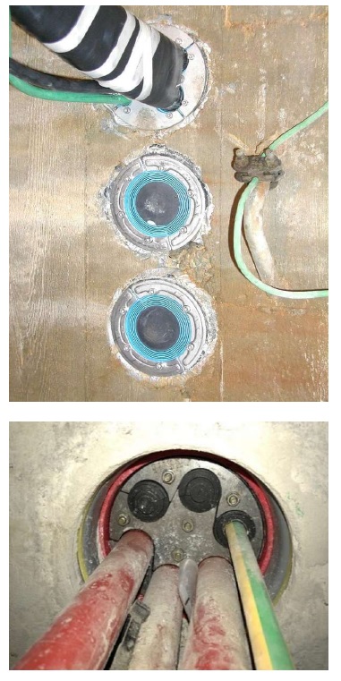
Mechanical sealing solutions, using standard or customised cable transits, that are purpose built for sealing underground ducts provide the highest level of protection. These solutions from Roxtec are typically a compressed rubber solution with tight tolerances that, when compressed, provide a water-tight seal that will contain a high level of water pressure for long term reliability(Figure 8). These solutions are designed for life of building duration or maintenance schedule.
Figure 8. Mechanical seals for fiber and power vaults. Purpose built seals that provide long term protection against water ingress
Sealing underground power and fiber ducts can be one of the most effective and least costly methods for protecting critical infrastructure from water and humidity. Without solutions that are purpose designed for stopping water, ducts can become a pathway for water ingress during flooding events. Even in less severe weather conditions, ducts can be a source of humidity which can effect short and long-term operational reliability of fiber and power systems.
Other areas that are potential points of water ingress include cable and pipe penetrations for:
Data Center Cooling/Rooftop penetrations(Figure 9)
Power systems (Generator/load bank, transformer/switchgear) exterior wall (Figure 10)
Fiber/Network Room
Figure 9. Rooftop penetration protected against water ingress
Figure 10. Large area building penetrations for power systems sealed against water ingress
These are all common points of water ingress that need to be protected. However, all penetrations through the building envelope should be evaluated as a potential leak path and appropriate solution applied to mitigate water ingress into the data center.
Conclusion
Downtime in data centers happens. Recent surveys show that downtime is still a concern for owners and that the reasons for downtime vary. Although most downtime occurs due to human error or mechanical issues, water related issues occur causing short and long term consequences. With proper design and site selection, water related issues in data
centers can be minimized. However, with climate change projections, data center fiber and power infrastructure will become more threatened by flooding and water ingress. Building away from coastal areas and outside of flood zones makes sense, but might not always be possible.
Based on a risk assessment of existing data centers, appropriate hardening measures can be taken to mitigate water ingress and protect power and fiber to ensure long-term operational reliability and uptime. For future data centers, designing and implementing purposed designed sealing solutions can offer the best long-term protection against the threat of water.
References
Uptime Institute, & Heslin, K. (2014). Data Center Industry Survey. [Online at https://Journal.uptimeinstitute.com/ 2014-data-center-industry-survey]
Information Technology Intelligence Consulting, & DiDio, L. (2017). Hourly Cost of Downtime and Minimum Reliability Requirements Survey.
The Ponemon Institute. (2010, September). National Survey on Data Center Outages. [Online at https://www.ponemon.org/local/ upload/file/Data_Center_Outages.pdf]
Department of Homeland Security. [Online at https://www.dhs.gov/ natural-disasters]
Miller, R. (2012, November). New York Data Centers Battle Back from Storm Damage. [Online at https://www. datacenterknowledge.com/archives/ 2012/11/01/ny-data-centers-battleback-from-storm-damage]
Heidemann, J., Quan, L., & Pradkin, Y. (2013, February). A Preliminary Analysis of Network Outages During Hurricane Sandy (USC/ISI Technical Report ISI-TR685b). [Online at https://www.isi.edu/ ~johnh/PAPERS/Heidemann12d.pdf]
Lima, J. (2016, January). Severe Floods in Leeds Hit Vodafone Data Centre. [Online at https://www. cbronline.com/news/data-centre/ severe-floods-in-leeds-hit-vodafonedata-centre-4767027/]
Zenium Technology Partners Limited. (2015). Managing Growth, Risk and the Cloud (Executive Summary of Independent Market Research Commissioned by Zenium Data Centers).
Uptime Institute. (2010 – 2014). Data Center Site Infrastructure Tier Standard: Operational Sustainability. [Online at https://uptimeinstitute.com/publicatio ns]
Bowman, R. & Deneny, T. (2014, November). Data Centers: Site Selection 101 | Site Selection Online. [Online at https://siteselection.com/issues/2012/ nov/data-centers.cfm]
Mena, M., Musilli, J., Austin, E., Lee, J.,
& Vaccaro, P. (2014). Selecting a Data Center Site: Intel’s Approach. (IT@Intel White Paper. Data Center Site Selection). [Online at https://media14. Connectedcom/intel/02/ 11447/IT_Best_Practices_Data_Center_ Site_Selection.pdf]
Telecommunications Infrastructure
(2012, August). Telecommunications Infrastructure Standard for Data Centers (TIA-942-A).
Uptime Institute. (2009 – 2018). Data
Center Site Infrastructure Tier Standard: Topology. [Online at https://uptimecom/publications]
(2014). ANSI/BICSI 002-2014.
Data Center Design and Implementation Best Practices.
Murray, J., & Andle, J. (2016). The Eye
on Medium Voltage Switchgear. Protecting critical assets with wireless monitoring. [Online at https://www. emerson.com/documents/automation/- eye-on-medium-voltage-switchgear-en38314.pdf]
van Heerden, C., & Rogerson, A. (n.d.).
Bushing Failures in Medium Voltage Switchgear. [Online at http://www. ameu.co.za/Portals/16/Conventions/Co nvention%202009/Papers/Bushing%20f ailures%20in%20medium%20voltage%2 0switchgear%20-%20Coetzee%20 van%20Heerden.pdf]
Genutis, D. (2010). Top Five Switchgear Failure Causes and How to Avoid Them. [Online at https://www.netaworld.org/ netaworld-journal/archived-articles/ 505]
(1997). Recommended Practice for the Design of Reliable Industrial and Commercial Power Systems. IEE std 493 – 1997.
Paoletti, G., & Baier, M. (2002). Failure Contributors of MV Electrical Equipment and Condition Assessment Program Development. IEEE Transactions on Industry Applications, 38(6), 1668 – 1676.
Schneider Electric Industries. (2018, June). Medium Voltage Technical Guide, Basics for MV Cubicle Design. [Online at https://www.schneider-electric.com/ en/work/products/product-launch/ medium-voltage-technical-guide/]
Mecheri, Y., Nedjar, M., Lamure, A., Aufrey, M., & Drouet, C. (2010). Influence of Moisture on the Electrical Properties of XLPE Insulation. 2010 Annual Report Conference on Electrical Insulation and Dielectric Phenomena (CEIDP). 1-4.
(2014). The Impact of Water on Fibre Optic Cable. [Online at https://www.idacs.uk.com/images/uploads/downloads/Datwyler_WP_Waterjmpact_FO_2014.pdf]
Grover, W. (2004, February). Fiber Cable Failure Impacts, Survivability Principles, and Measures of Survivability. InformIT. [Online at http://www.informit.com/articles/articlaspx?p=169456]
Fu, G., Horrocks, L., & Winne, S. (2016)
Exploring impacts of climate change on UK’s ICT Infrastructure. Proceedings of the ICE Infrastructure Asset Management, 3, 1,42-52
Dawson, R.J., Thompson, D., Johns, D.,
Gosling, S., Chapman, L., Darch, G., Watson, G., Powrie, W., Bell, S., Paulson, K., Hughes, P., & Wood, R. (2016). UK Climate Change Risk Assessment Evidence Report: Chapter 4, Infrastructure. Report prepared for the Adaption Sub-Committee of the Committee on Climate Change, London
Horrocks, L., Beckford, J., Hodgson, N.,
Downing, C., Davey, R., & O’Sullivan, A. (2010). Adapting the ICT Sector to the Impacts of Climate Change – Final Report, Defra contract number RMP5604. AEA group, published by Defra.
Melillo, J.M., Richmond, T.C., & Yohe, G.W., Eds. (2014). Climate Change Impacts in the United States: The Third National Climate Assessment. U.S. Global Change Research Program, 841 pp. doi:10.7930/J0Z31WJ2.
Karl, T.R., Melillo, J.T., & Peterson, T.C., Eds. (2009). Global Climate Change Impacts in the United States. Cambridge University Press, 189 pp. [Available online at http://downloads. globalchange.gov/usimpacts/pdfs/ climate-impacts-report.pdf]
Thorne & Derrick are national distributors of LV, MV & HV Cable Installation, Jointing, Substation & Electrical Equipment – servicing businesses involved in cabling, jointing, substation, earthing, overhead line and electrical construction at LV, 11kV, 33kV, 66kV and EHV. Supplying a complete range of power cable accessories to support the installation and maintenance of low/medium and high voltage cable systems:
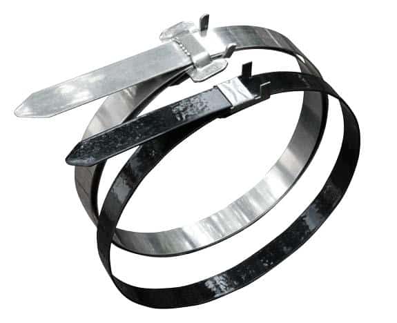
BAND-FAST is a versatile Cable Clamping System for harsh, hazardous and high-performance industrial cable support applications – the cost-saving cable banding solution comprises stainless steel pre-cut banding with pre-assembled buckle.
This IEC61914 compliant cable management system provides installers with significant labour productivity gains of up to 30% and up to 75% material cost savings compared to cable cleats for the short-circuit retention and support of power cables.
Two options are available: a PPA Coated version and an Uncoated version with captive clip both manufactured from type 316 stainless steel – high strength, compact flat profile, space and weight saving, non-corrosiveand fire resistant.
The cable clamps have successfully been utilised on the following applications:
BAND-FAST cable clamps are also available in highly corrosion resistance materials including: Monel®, Alloy 625, Zeron100 and 316 Stainless Steel for the attachment of polyurethane mouldings, saddles, protectors and piggy-back clamps in subsea energy projects.
BAND-FAST cable clamps
Advantages
Purchase price is significantly lower
–Up to 75% material cost savings
Installation time is dramatically reduced
–Reduce labour cost up to 50%
Low smooth profile
–Space savings on construction
More versatile
–Conforms to most shapes / cable configurations
Large diameter reduction (one size fits all)
–Fewer SKU’s to order / stock
No accessories required
–No nuts / bolts / packing blocks
Lighter weight cable clamps
–Reduced weight on construction
–Easier to carry around site
–Safer during installation at height
Cable Cleat Standard IEC61914
The cable clamps are independently tested to the latest Cable Cleat Standard IEC61914 for resistance to electromechanical force.
Short Circuit Testing of BAND-FAST Clamps
Subjected to 2x Short Circuits and dielectric test after wetting
PPA Coated BAND-FAST Cable Clamps By BAND-IT
Tests conducted to IEC61914
“Tests for Resistance to Electromechanical Force” Section 6.4.3 and 6.4.4.
➡ The following tables enables the selection of the correct BAND-FASTcable clamp manufactured by BAND-IT based on 300mm spacing between clamps according to IEC61914. Request Test Data for 600mm spacing of BAND-FAST clamps.
BAND-IT Part Number
Width
Band Ref/Material
Length (mm)
Clip/Ref Material
Single Wrap or Double Wrap
*Max Cable OD (Single cable config)
*Max Cable OD (Trefoil cable config)
*Max Cable OD (Quadrafoil cable config)
Pack qty Piece
Weight Per Piece (kg)
**Pass IEC61914 Short circuit test in trefoil up to (KA PEAK)
LFAC-F1015M030–A900
15.88mm (5/8”)
AE435
316 SS
300
AE455
316 SS
Single
40mm
13mm
12mm
100
0.025
50.8kA
LFAC-F1015M040–A900
400
75mm
28mm
25mm
100
0.030
LFAC-F1015M050–A900
500
100mm
43mm
37mm
100
0.038
LFAC-F1015M060–A900
600
130mm
57mm
50mm
100
0.045
LFAC-F1015M070–A900
700
160mm
70mm
60mm
100
0.052
LFFC-F1015M040–A900
400
LE155
316 SS
1Double
40mm
13mm
12mm
100
0.030
76.3kA
LFFC-F1015M050–A900
500
55mm
21mm
18mm
100
0.038
LFFC-F1015M060–A900
600
70mm
28mm
25mm
100
0.045
LFFC-F1015M070–A900
700
85mm
35mm
31mm
100
0.052
LFFC-F1015M080–A900
800
100mm
42mm
37mm
100
0.060
LFFC-F1015M100–A900
1000
130mm
57mm
50mm
100
0.075
LFFC-F1015M120–A900
1200
160mm
70mm
60mm
100
0.090
Ref C075 Bantam Tool for application of all PPA Coated BAND-FAST® Clamps
1.040
Uncoated BAND-FAST Cable Clamps installed with additional cushion sleeve
BAND-IT Part Number
Width
Band Ref/Material
Length (mm)
Clip/Ref Material
Single Wrap or Double Wrap
*Max Cable OD (Single cable config)
*Max Cable OD (Trefoil cable config)
*Max Cable OD (Quadrafoil cable config)
Pack qty Piece
Weight Per Piece (kg)
**Pass IEC61914 Short circuit test in trefoil up to (KA PEAK)
LFEC-F1030M050
15.88mm (5/8”)
C405
316 SS
500
C455
316 SS
Double
55mm
21mm
18mm
100
0.062
112kA
LFEC-F1030M060
600
70mm
28mm
25mm
100
0.070
LFEC-F1030M070
700
85mm
35mm
31mm
100
0.078
LFEC-F1030M080
800
100mm
42mm
37mm
100
0.086
LFEC-F1030M100
1000
130mm
57mm
50mm
100
0.103
LFEC-F1030M120
1200
160mm
70mm
60mm
100
0.120
LFEC-F1230M050
19.1mm (3/4″)
C406
316 SS
500
C456
316 SS
Double
55mm
21mm
18mm
100
0.078
120kA
LFEC-F1230M060
600
70mm
28mm
25mm
100
0.088
LFEC-F1230M070
700
85mm
35mm
31mm
100
0.098
LFEC-F1230M080
800
100mm
42mm
37mm
100
0.108
LFEC-F1230M100
1000
130mm
57mm
50mm
100
0.128
LFEC-F1230M120
1200
160mm
70mm
60mm
100
0.150
Ref C001 Band-It® Tool for application of all Uncoated BAND-FAST® Clamps
2.000
*Note: Maximum cable OD are for a guide only.
Short Circuit Test Videos
PPA Coated BAND-FAST® Cable Clamps with Clip. Test Video #33 70.1kA (2nd Shock – 600mm Spacings).
Thorne & Derrick are Specialist Distributors to international Utilities, UK DNO’s, ICP’s and HV Jointing Contractors of an extensive range of LV HV Cable Jointing, Substation, Tooling & Installation Equipmentfrom 600V to 66kV – we service wind energy, solar power, battery storage, rail, utility, datacentre and the explosive atmosphere industries.
Based in the UK, we are highly customer responsive and absolutely committed to providing a world-class service.
Since 1985, we have provided expert technical support and express delivery from extensive UK stocks to world-wide destinations.
Celebrating Charlie & Ella’s Level 4 Sales Executive Apprenticeships At Thorne & Derrick International, we are proud to champion talent development and recognise the dedication required to achieve professional growth. We are therefore delighted to congratulate Charlie Baines and...
Thorne & Derrick will be Exhibiting at Solar & Storage Live UK 2026 at the NEC Birmingham from 22nd–24th September, showcasing our support for HV Cable Accessories, Joints, Terminations, Separable Connectors, Cable Tooling and Grid Connection Products used across...