

Blog
Modular Substation Cable Termination Design | Roxtec Whitepaper
May 11th, 2021
Abstract
The methods for cable penetrations into modular industrial substations are summarised using cable transits manufactured by Roxtec.
The requirements for structural and environmental integrity, grounding, sealing, fire protection and ease of expansion for a cable termination system are discussed. Current methods of installation are compared to using a cable transit design for installing and terminating cables in electrical substations.
Index Terms – cable termination, modular substation, cable transit.
Introduction
Modular substations are becoming the preferred approach for installing electrical and control equipment in industrial facilities.
The ability to prefabricate a building, pre-install both electrical and control equipment and the ability to pre-commission equipment prior to the installation helps to reduce on-site construction installation costs. This is particularly advantageous in remote project locations where the cost of labour can be very high.
The on-site termination of conductors and cables into equipment can often be an issue.
The equipment layout, the design of the modular building skid base frame, the number of terminations and the termination method can all influence the speed and ease of installation. Choosing the wrong penetration approach can compromise the environmental integrity of the building and equipment, significantly increase installation cost and complicate the ability to install cables and conductors in the future.
This has a direct impact on the cost of ownership over the life of the asset.
Modular Substation Fundamentals
A typical modular substation consists of a steel frame skid base supporting a prefabricated insulated panel constructed building.
The dimensions of the building can vary and is usually determined by the amount of equipment installed and the transportation logistics for a project.
It is common to see substation buildings with dimensions in excess of 30 meters in length, 7 meters wide and 6 meters high for domestic onshore projects. If the equipment layout dictates a larger building footprint, often the building will be split in two for transport to site.
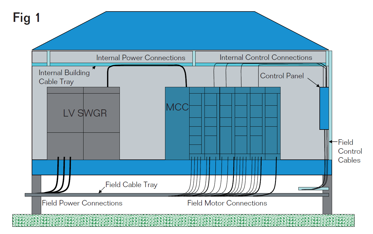
Interconnecting wiring between equipment is usually done in one of two ways. If the substation is constructed on raised piles, and the wiring connections are internal to the substation, the conduits or cables are run overhead within the substation.
External field cable connections are then terminated into the floor of the substation directly into the equipment item. This approach has the advantage of minimising the height of the building and allowing for convenient access for workers to terminate field cables.
Fig. 1 illustrates this concept.
Modular Substation Cable Termination Design | Figure 1
Terminating Cables in substations
There are a number of challenges associated with terminating cables in a modular substation.
The first being the number of field terminations. In a medium sized industrial substation servicing a large number of motor interconnections, there may be up to 300 or more power and control cable terminations. The terminations must be coordinated with the location of the electrical and control equipment and the skid frame steel members supporting the building.
Often, a large number of cables must be terminated in a very limited area leading to cable and connector congestion which can impact worker productivity. Another challenge associated with terminating field cables is maintaining the environmental integrity of the equipment and the substation building envelope. This requires that the termination method maintain a vapour-tight weather barrier with a suitable insulation ‘R’ factor value to avoid condensation within the equipment and the building envelope.
The cable termination method should also provide a fire resistant barrier in the unlikely event of a fire. The cable termination method must accommodate a variety of cable construction configurations and wiring methods.
Cable diameters can vary with some control conductors with diameters of 5 mm or less to 3/C 500MCM armoured power cables which may have diameters of 100 mm or more. In each case, the cable must be properly secured and grounded in accordance with the local electrical installation codes and requirements. One often overlooked aspect of the cable termination method is the ability to add cables in the future.
The flexibility to easily add additional cable can pay dividends even during the initial installation when design modifications are made late in the installation phase of a project.
Traditional cable termination options
There are several cable termination methods currently used to terminate conductors into industrial substations. Some projects prefer that all cables are terminated into the top of electrical and control equipment mounted inside the building. A cable transit barrier is often used to allow cables to pass through an exterior wall.
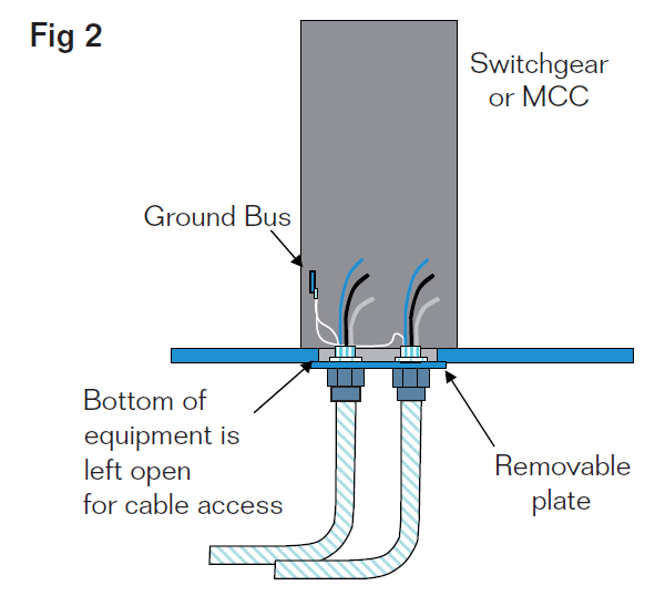
Fig. 2 illustrates a method where cables are terminated into the floor of a substation. A ¼” steel removable panel is used to facilitate the pre-drilling of holes for the cable connectors prior to the field installation. This helps to improve construction productivity by allowing the majority of the cable connector entry holes to be drilled in a shop environment. Once the connector plate is fastened in place, drilling becomes more difficult and time consuming.
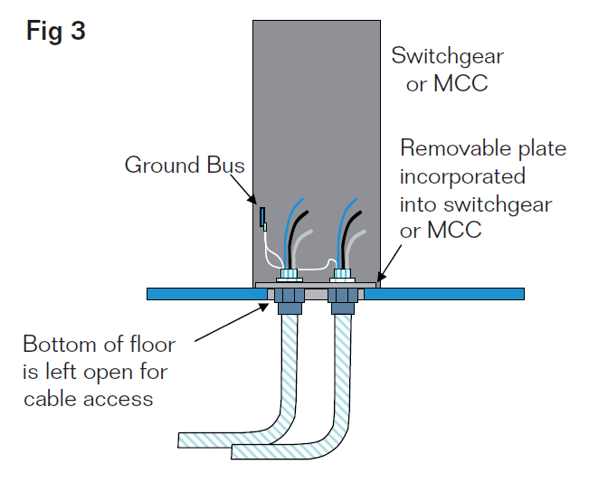
There is also the potential for metal filings to contaminate the switchgear cable termination compartment. Each connector hole must also be de-burred to prevent the conductor insulation from being damaged when the cable conductors are pulled into place. A second option for terminating cables is illustrated in Fig. 3.
A section of the floor is removed and the cable is terminated directly into the floor mounted equipment. Some equipment, such as low voltage motor control centres (MCCs) incorporate a removable plate to facilitate the punching of holes for cable connectors. The removable plate is usually constructed of sheet metal steel and is easily punched using a hydraulic punch.
The primary disadvantage to this termination method is that large sections of the floor must often be removed to gain access to the underside of the equipment. This may compromise the structural integrity of the floor and building envelope.
Future cable entry is also difficult as access to the plate must be provided both above and below the cable connector location. In certain cases, if the plate is not of sufficient thickness, large cables can deform the plate, further compromising the integrity of the installation.
Cable Termination into Floor of Substation | Figure 2
Cable Termination directly into Switchgear/MCC | Figure 3
Improved cable termination option
using a cable transit system
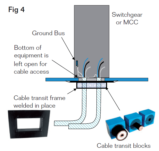
A third option for terminating cables into a substation is to use a transit entry frame. Fig. 4 illustrates a transit entry installation.
The transit frame is welded or bolted to the substation floor at strategic locations where cables will be terminated. The cables are then pulled into place through the transit frames and then sealed using Multidiameter™ cable transit blocks and a mechanical compression wedge.
The cable transit system provides cable retention and provides an environmental, fire resistant and gas tight seal to the equipment and building enclosure. There are several advantages to using a cable transit for cable entry in to a substation. The first being efficiency.
A cable transit allows multiple cables to be pulled at the same time though the transit opening. The large opening eliminates the potential damage to the conductor insulation during installation. Secondly, the transit frame maintains the structural and environmental seal integrity of the floor and allows for a high density and capital efficient installation of cables within a very small footprint. Also, future expansion capacity is provided for each transit via unused cable blocks which can be easily removed and reinstalled for future cable installation.
Another significant advantage of sealing cables with a cable transit system is the additional room below the building floor and equipment that is provided by the extension of the transit frame. This depth may be customised to a depth equal to the height of the structural steel, and has a standard depth of 60 mm.
This additional working space assists with the restrictive bend radius of larger armoured cables and allows for proper cable alignment with equipment configuration.
Cable Transit Installation for Switchgear/MCC Entry | Figure 4
Equipment Grounding for Tray Cables
There are two methods for terminating the bonding conductor of a tray cable using a cable transit system. The first involves connecting the bonding conductor directly to the ground bus of a switchgear or MCC. The PVC sheath is stripped back to the transit entry location and the bonding conductor is removed and connected to the equipment ground bus. The phase conductors then continue to the termination point in the switchgear or MCC. This is very similar to what occurs when a standard cable connector is used to terminate a conductor. Fig. 5 illustrates this method of bonding.
A second and less labor intensive option exists for grounding tray cables in MCCs. Some MCC manufacturers provide the option of a “unit” ground connection at the MCC bucket rather than on the equipment ground bus. This reduces the amount of cable sheath that must be stripped back in order to connect the bonding conductor to the equipment ground bus. This has the advantage of keeping the phase and bonding conductors together as an assembly within the equipment and breaking out the bonding conductor closer to where the phase conductor terminations actually occur. Fig. 6 illustrates this method of bonding.
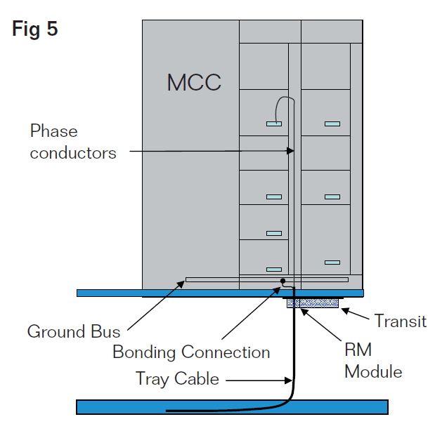
Option 1 for Grounding Tray Cable | Figure 5
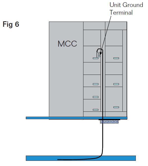
Option 2 for Grounding Tray Cable | Figure 6
Work process
To use a cable transit system to its fullest advantage, an understanding of the work process from design through final installation is required.
A. Engineering
The use of a cable transit for terminating cables into a substation requires pre-planning. The location of electrical and control equipment must be coordinated with the structural steel base to insure that transit frames of an adequate size and dimension can be installed without interference from support steel in the steel base. If possible, a standardised frame size helps to simplify the
design and installation process.
During the design phase, as cables are identified, they are assigned to a transit frame. This information can be integrated into the cable schedule or often dedicated software is used to create detailed transit schedules. Once the transit schedules are complete, the bill of material can be generated for both the substation fabricator and field installation contractor.
Fig. 7 illustrates a typical engineering drawing produced by Roxtec RTM Software for an MCC transit with capacity for 43 cables of various diameters installed within a 23 cm x 26 cm window. The flexibility of this system allows cable and pipe sizes ranging from 3 mm (.118 in) to 99 mm (3.898 in) to be sealed within the transit frames.
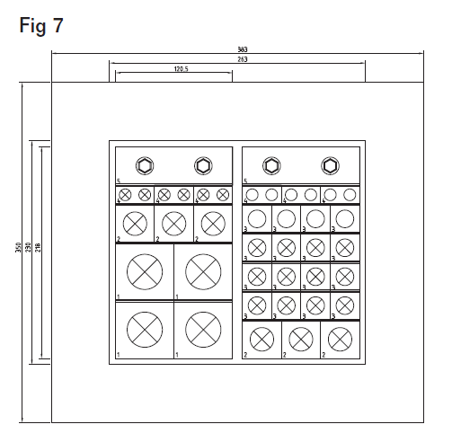
Engineering Drawing of Cable Transit System | Figure 7
B. Fabrication
Once the size of the cable transit and the locations are identified, the transit frames can be purchased and shipped to the fabricator for installation. The transit frames are mounted into the wall or floor by bolting or welding and then temporarily sealed for transportation to site.
C. Site Installation
After the modular substation is shipped to site and set in place, installation of the field conductors can begin. The site installation contractor will install interconnecting cables from source to destination via the cable transit openings identified on the cable schedule. The large opening provided by the cable transit helps the installer pull the cable into place and minimises any damage to the conductor insulation. When all cables for a cable transit are installed, the cables are secured and sealed using the cable transit blocks with stay plates and a mechanical compression wedge. The cable transit drawings help to identify what cables should be placed where and what size cable block should be used. The transit schedules also record how much spare capacity is available in each cable transit for future growth. Cables can be easily added without cutting or drilling additional holes, simply by loosening the compression wedge. Training is essential to help field installers understand the transit termination concept.
Training can be provided using on-site training services or by installation videos that provide step-by-step instructions. Once the installer has observed and installed the transit blocks for one transit installation, subsequent transit installations are easily completed. Figure 8 illustrates the installation of a transit barrier in a modular substation application.
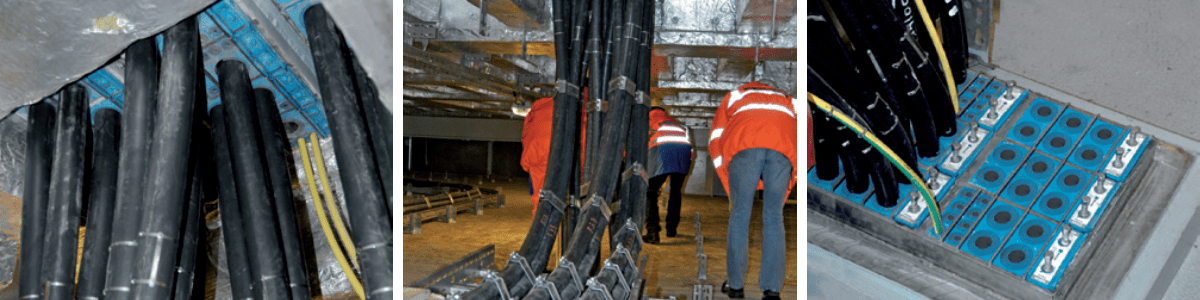
Figure 8
Conclusion
There are several advantages to using a cable transit for installing and terminating cables in industrial substations. It provides a standardized design with the flexibility to terminate a variety of different sizes and cable constructions. The ease of installation helps to reduce labor costs and minimize the potential for insulation damage. The structural and environmental integrity of the wall or floor penetration is maintained providing an insulated, vaportight and fire-stop barrier and cables can be easily added in the future. Cable transits are a viable alternative for terminating cables into industrial substations.
H. Vita
Allan Bozek, P.Eng., MBA graduated from the University of Waterloo in 1986 with BASc in Systems Design Engineering and a MBA from the University of Calgary in 1999. He is a Principal with EngWorks Inc., providing consulting engineering services to the oil and gas sectors.
Roxtec International AB, the parent of Roxtec, Inc. was established in 1990 and is the global leader in modular cable and pipe sealing systems. Roxtec maintains more than 250 registered tests and approvals and serves the oil & gas, telecom, marine, industrial and OEM industries in more than 70 markets around the globe.

LV MV HV Jointing, Earthing, Substation & Electrical Eqpt | Distributors for Roxtec Cable & Pipe Sealing Transit Systems
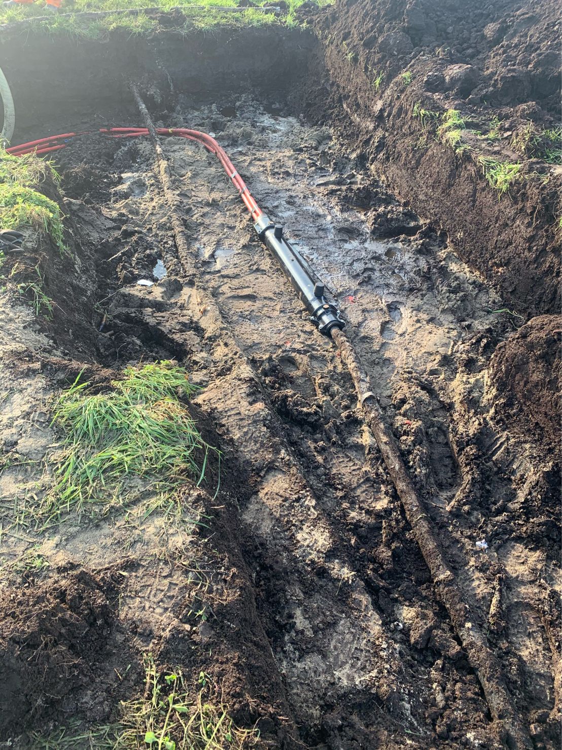
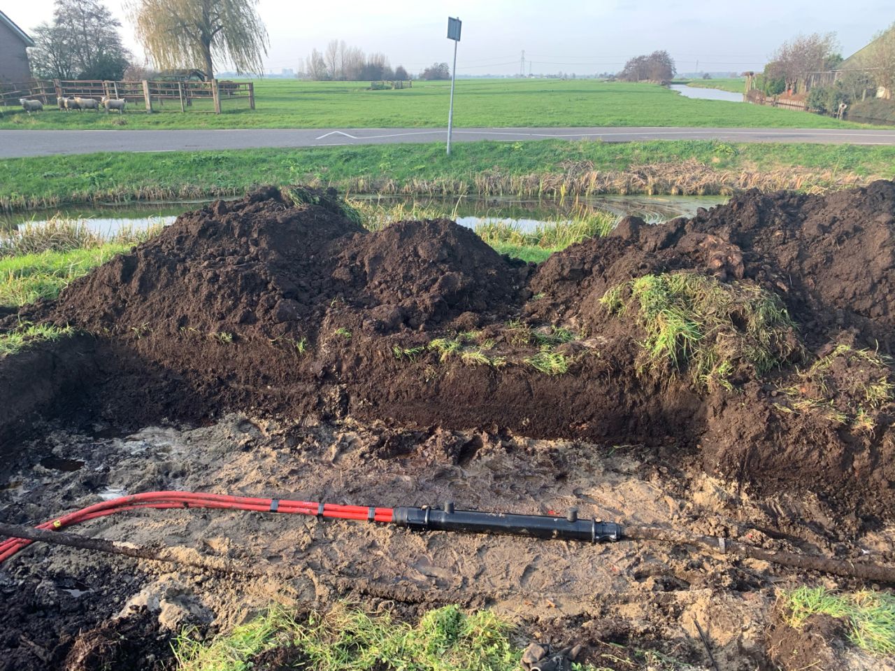
Kabeldon SMTXB Cable Joint
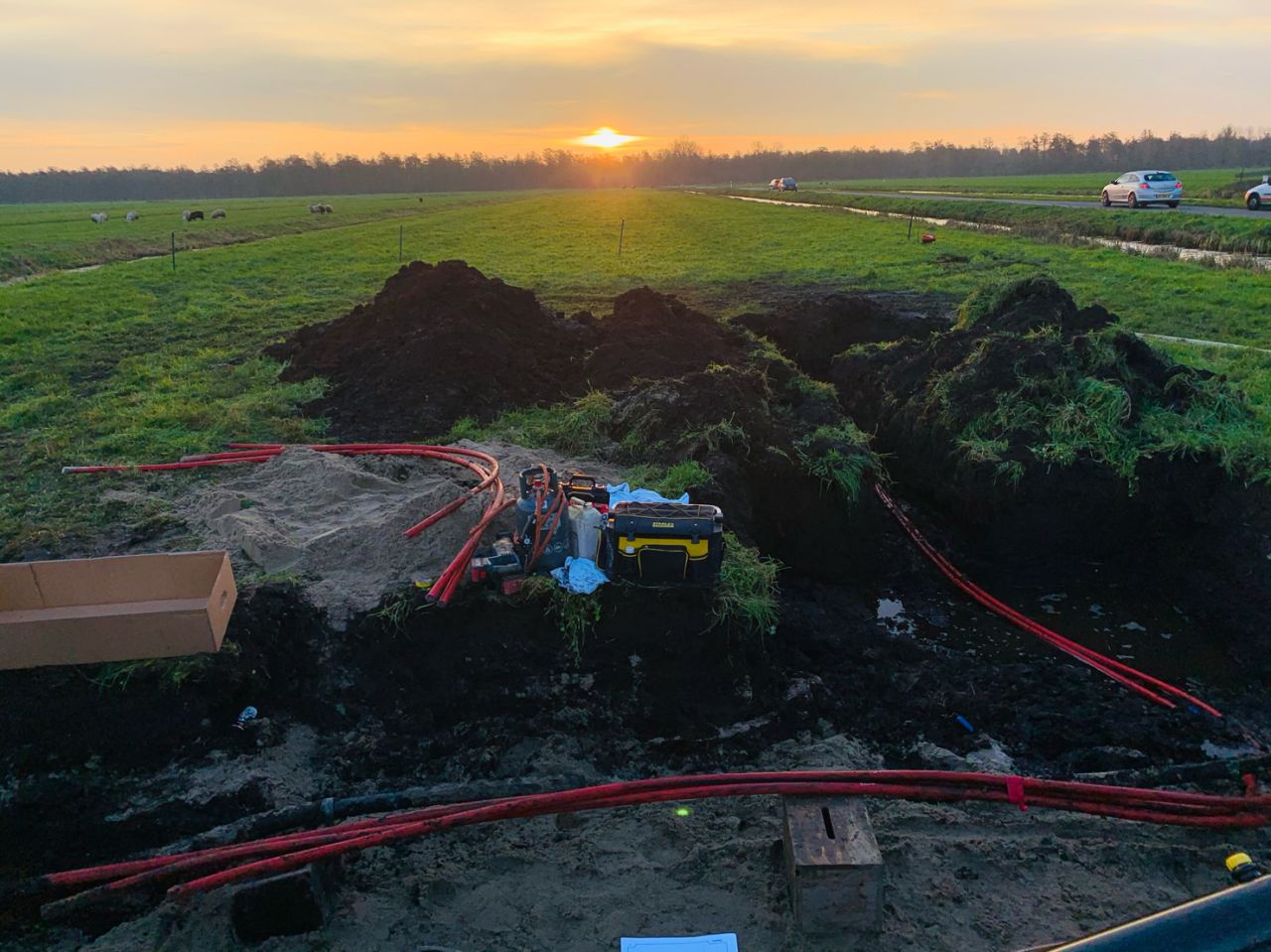
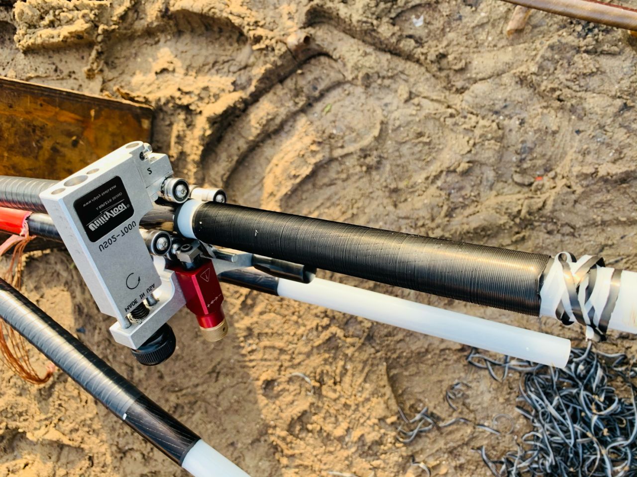
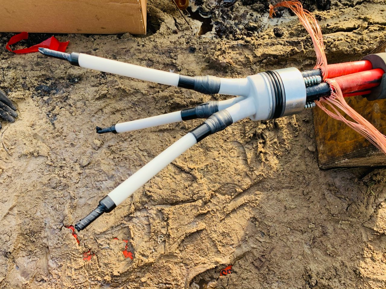
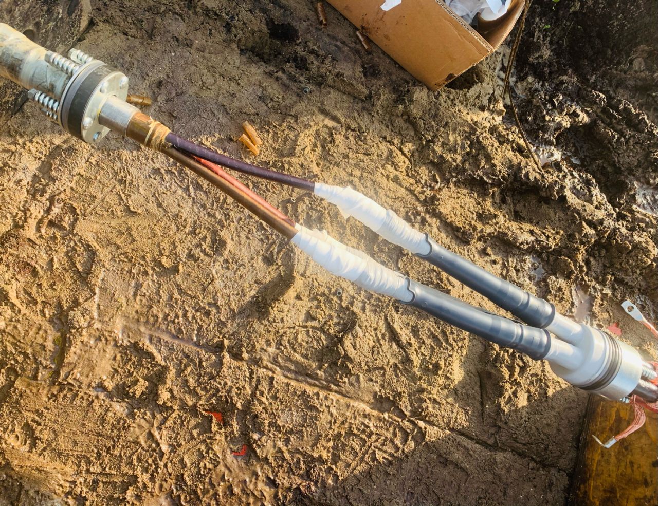
May 11th, 2021Images Coutesy of: Timo van der Harst – Eigenaar VDH Kabelmontage Laag- en Middenspanning, Vlaardingen, South Holland, Netherlands
Pictured: Kabeldon SMTXB Cable Joint

Jointers blog
Subscribe now to our POWER NEWSLETTER– a monthly email circulation packed with news, projects, videos, technical tips, training information, promotions, webinars, career opportunities and white papers.
Includes access to our popular JOINTERS BLOG with contributions from utility professionals, linesmen and cable jointers working on MV HV EHV cables and overhead lines typically at 11kV, 33kV, 66kV and up to 132kV.
15,000+ Subscribers. ➡ 
3M Scotch Super 33+ Vinyl Electrical Tape
May 11th, 2021
3M Scotch Super 33+ Vinyl Electrical Tape
3M Electrical Tapes
Scotch Super 33+ Tapes
When it comes to the your most demanding electrical maintenance and repair jobs where failure and equipment downtime are simply not an option look no further than the 3M Scotch Super 33+ Vinyl Electrical Tape.
The vinyl electrical tape has excellent resistance to abrasion, moisture, alkalies, acids, corrosion and varying weather conditions (including UV exposure) and forms part of the 3M Scotch Electrical Tapes. Scotch Super 33+ can be used in hot or cold temperatures, high humidity or in contact with contaminants and aggressive substances making the tape suitable for inside and outdoor environments.
Highly conformable and super-stretchy and designed to perform continuously in ambient temperatures up to 105 °C
Scotch® Super 33+™ Vinyl Electrical Tape is designed for:
- Primary electrical insulation of electrical connections up to 600V
- Protective cable jacketing and repairs
- Weatherproofing
- Harnessing of wires and cables

Thorne & Derrick – 3M Electrical Stockists & Suppliers | Scotch Tapes | Scotchcast Resins | Cold Shrink Products | UK & Export Sales
3M Scotch Super 33+ can be used in combination with other 3M professional tapes.
| 3M Tapes | Tape Description | 3M Tape Image |
| Scotch Vinyl Colour Coding Electrical Tape 35 | Scotch Vinyl Colour Coding Electrical Tape 35 is the professional grade vinyl electrical tape available in nine fade resistant colours: blue, brown, grey, green, orange, red, violet, white, yellow, and pink. Outstanding electrical and mechanical properties make this tape excellent for use in phase identification, colour coding of motor leads and piping systems, and for marking safety areas. Scotch® Tape 35 applies smoothly and conforms well down to 0 °C. Maximum operation temperature is 105 °C. |
 |
| Scotch Rubber Splicing Tape 23 | Scotch® Rubber Splicing Tape 23 is made from Ethylene Propylene Rubber. This product fuses to itself in a short time after application to create a solid piece of rubber with high dielectric properties and is impenetrable by moisture. It’s a great option when working on jobs with voltage up to 69 kV. Split resistant, crack resistant and flag resistant within harsh environments. Rated for 90 °C continuous operating temperature and over- load temperatures of up to 130 °C. Scotch® Rubber Splicing Tape 23 features a liner, making it easy to cut and apply the tape in strips and in messy environments. |
 |
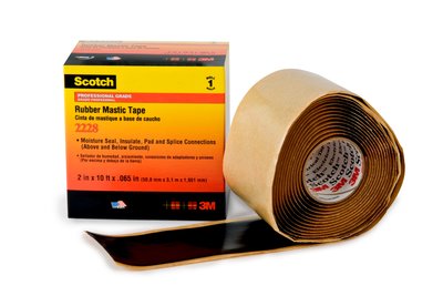
| Scotch Rubber Mastic Tape 2228 | This product combines the advantages of rubber and mastic tapes for fast application. Scotch® Rubber Mastic 2228 is a conformable self-fusing rubber electrical tape designed for electrical insulating and moisture sealing applications at 90 °C with an emergency overload rating of 130 °C. It is flexible and conformable over irregular shapes. The thick construction allows quick application build-up and padding, good for cable jacket repair. It is UV resist- ant and has excellent adhesion and sealing characteristics with copper, aluminium and power cable jacket material. |
 |
| 3M Scotchfil Electrical Insulation Putty | 3MTM Scotchfil Electrical Insulation Putty is a noncorrosive electrical grade compound in a tape form, easy to mould by hand down to 0 °C. It’s a great solution for smoothing uneven surfaces and eliminating voids until good overall padding is provided. 3MTM Scotchfil Putty is recognized as a splice insulation for electrical conductors at temperatures up to 80 °C when overwrapped with Scotch® Super 33+TM. |  |
➡ Specialist Application 3M Scotch Tapes: Fire Retardant, Fire Resistant, Arc Proofing, Cable Sheath & Jacket Repairing, Bundling & Harnessing Cables.
3M Scotch Electrical tapes are used to cable joint, splice, repair, seal and protect cables against abrasion, fire and corrosion – this includes LV-HV (11kV-33kV cables) – please contact T&D should you require assistance with selecting the correct tape.

Brugg Cable Tools For Jointing & Straightening HV EHV Cables
May 11th, 2021
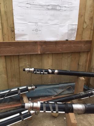
Image: Dean Wilson – Owner Director at D.C. Jointing Ltd
D.C. Jointing Ltd are Specialist Electrical Cable Jointers with a team of 15 skilled staff in all aspects of offshore and onshore cable jointing up to 132kV, including cable jointing LV, HV and EHV, major projects with Regional Electricity Companies, onshore wind farms, offshore windfarms, power stations and National Grid.
Pictured: Brugg Cable Tools For Jointing & Straightening HV EHV Cables
BRUGG CABLES
The development of high voltage XLPE Cable Systems goes back to the 1960’s. Since then production and material technology have significantly improved, to provide reliable and maintenance-free products to the utility industry.
At present, numerous high voltage XLPE cable systems with nominal voltages up to 500 kV and with circuit lengths up to 40 km are in operation worldwide.

Cable systems are equipped with accessories, which have passed the relevant type tests pursuant to national and international standards, such as long-duration tests. As one of the first XLPE cable manufacturers worldwide Brugg Cables passed a Prequalification Test on a 400 kV XLPE Cable System according to the relevant international standard IEC 62067 (2001).
This test required one year of operation, along with the thermal monitoring of all cables, joints and terminations installed. It was successfully completed at CESI Laboratory in Milan, Italy in 2004.
As one of just a few providers worldwide, Brugg Cables can offer a broad range of both XLPE cables (up to 500 kV) and oil-filled cables (up to 400 kV) as well as their accessories.
Jointers blog
Subscribe now to our POWER NEWSLETTER– a monthly email circulation packed with news, projects, videos, technical tips, training information, promotions, webinars, career opportunities and white papers.
Includes access to our popular JOINTERS BLOG with contributions from utility professionals, linesmen and cable jointers working on MV HV EHV cables and overhead lines typically at 11kV, 33kV, 66kV and up to 132kV.
15,000+ Subscribers. ➡
Top Benefits of High-Voltage Direct Current (HVDC) Transmission
May 11th, 2021
A Benchmark Brief
from Burns & McDonnell
Burns & McDonnell are a family of companies with an unmatched team of 7,600 engineers, construction professionals, architects, technologists and scientists. Their singular mission since 1898 has been to make clients successful – ‘When we plan, design, permit, construct and manage projects worldwide, we do it like we own it.’
Burns & McDonnell is a 100% employee-owned company who tackle every technical challenge, every complex detail, with the intent and attention of an owner. It’s what brings clients back, project after project.
Benefits of HVDC Transmission
As the demand for power is increasing, government policies are providing incentives to utilities for adopting renewable energy sources. Utilities are investing time and money to improve the transmission of renewables from offshore wind and solar.
Today, most power grids use high-voltage alternating current (HVAC) for transporting energy over long distances, but that technology is susceptible to losses during transmission, has limits on power transfer over long distances, and has limited power control capability. A high-voltage direct current (HVDC) system converts the power from alternating current (AC) to direct current (DC) at the sending end, transmits the power using DC, converts the power back from DC to AC at the receiving end, and delivers the power to the receiving end AC grid.
Application of HVDC technology is expanding not only for large bulk power transfer over long distances, but also in the interconnection of renewable energy sources.
Bulk Power Transmission Efficiencies
Transmission cost depends on numerous factors, such as the size and quantity of conductors, equipment needed at the terminal stations, and transmission tower size.
HVDC is particularly well suited for bulk power transmission over long distances for several reasons:
- A bipolar HVDC system consisting of two high-voltage conductors on one tower offers reliability comparable to a double-circuit HVAC line, significantly reducing the transmission line costs and right-of-way requirements.
- Losses in a transmission line depend on the resistance of the line. One factor that impacts the resistance is skin effect, which causes the effective resistance to increase with increasing AC frequency. Use of DC eliminates the skin effect, reducing overall transmission losses.
HVDC transmission systems require converter stations at each end of the line to convert the AC to DC and back. Cost of HVDC converter stations can be substantially more than a conventional AC substation with similar power throughput. That expense may be counterbalanced by reduced transmission line costs and reduced losses. This becomes more evident as the distance and/or power transfer level increases.
Cable Length Advantage
HVAC transmission cable length is limited because as the length of cable increases, the capacitive charging current increases. It can reach a point that the capacitive charging current approaches the total current carrying capacity of the cable. HVDC has no capacitive charging current, and higher levels of power can be delivered over longer distances. HVDC cable length is theoretically only limited by capital cost. Enabled applications include:
- Connection of offshore wind farms: As development of offshore wind generation assets increases, the location of wind turbines generators is moving farther from the shore. The increasing distances between the generators and the onshore point of interconnection means the necessary cable length is increasing. HVDC can be a viable transmission option, unlocking the true potential of renewable energy.
- Transmission into congested areas: Increasing demand, particularly in congested areas, coupled with challenges of accessing rights-of-way has driven the need to maximize power transfer and a push to go underground. HVDC is an excellent option for high-power cable transmission installations, maximizing the amount of power transfer per cable.
Power Controllability
Within an HVAC system, the ability to control power flows in any given parallel path is limited. Power flows are dictated by the relative impedance of various parallel paths from a given source of generation to a given load. HVDC, on the other hand, offers very fast and accurate control of the power flowing within its system. The operator can select the amount of power to be transmitted over the link. If that power is available at the sending end, it is then converted to DC, transmitted to the receiving end, converted back to AC and injected into the receiving AC system. Auxiliary control functions can further enhance AC system’s stability by providing frequency control and damping of power swings within the AC grid.
HVDC systems offer higher transmission capability and lower transmission losses over long distances than AC and provide better ability to control power flows. Additionally, they provide the ability to transmit more power over longer lengths of cables, making them an attractive alternative for the transition to renewable energy sources.

T&D | LV MV HV Cable Installation, Jointing, Substation & Electrical Equipment
Thorne & Derrick
T&D are Specialist Distributors to UK Distribution Network Operators (DNO’s), NERS Registered Service Providers, ICP’s and HV Jointing Contractors of an extensive range of LV, MV & HV Jointing, Earthing, Substation & Electrical Eqpt – this includes 11kV/33kV/66kV cable joints, terminations and connectors for both DNO and private network applications.
Contact our UK Power Team for competitive quotations, fast delivery from stock and technical support or training on all LV-HV products.
All international sales enquiries can be serviced and supplied by our Export Power Team.
Key Product Categories: Duct Seals | Cable Cleats | Cable Glands | Electrical Safety | Arc Flash Protection | Cable Jointing Tools | Cable Pulling | Earthing | Feeder Pillars | Cable Joints LV | Joints & Terminations MV HV



