The following article on Cable Asset Management has been published with the kind permission of ERPA.

ERPA (Electric Power Reliability Alliance) are a collaborative practitioner community that works to advance awareness and understanding of electric power reliability.
ERPA are a “practitioner-to-practitioner” collaborative community, bringing proven and practical resources and shared experiences to practitioners in the industrial and commercial markets.
A reliable power system is the lifeblood of any production facility, distribution system, data center or business.

Join a growing community of industrial and commercial electric power reliability practitioners.
Cable Asset Management
A Scientific Approach to Cable Asset Management
By Ben Lanz, Director, Applications Engineering, IMCORP. Member, EPRA
Power Cables | Cable Care
Power cables are one of the most commonly overlooked power system assets and are, by default, typically addressed reactively after failure. They are also one of the most misunderstood. This article provides insight into how new scientific findings on cable care address these misunderstandings. In this article I will provide insight into some of these findings through case studies, and I’ll explain how a holistic, condition intelligence-based strategy can easily double the expected life of most assets — including cables — and maximize reliability with optimal life cycle cost.
Most medium- and high-voltage cable systems consist of plastic and rubber (solid dielectric) insulation. A significant percentage of assets containing those materials are reaching—or have passed—their assumed 30- to 40-year end-of-life. Asset managers are now facing a significant challenge in balancing reliable power delivery with budget priorities. As new assets are installed, reliability professionals are asking, “how can we make cable systems last longer with higher reliability?”
Cable Asset Management Best Practices
This broad reliability question comprises several smaller and more practical questions, which have been answered here with input from cable owners from all over the world. With their help, we have assembled the largest condition assessment database of its kind—and the findings are good news for cable owners.
We discovered that to extend the life of medium and high voltage cables, there are two key things to consider when developing a reliability plan, supported by four best-practice recommendations:
A. Practice “cable care” techniques.
With the proper care and maintenance, aged cable systems can outperform new cable systems.
B. Eliminate physical stressors and extreme duty stressors.
With these additional stressors removed, it is possible to extend the reliable life of cable to 100 years— and beyond.
C. Follow best practices
- Install and maintain over voltage protection.
- Perform IR inspection of connectors.
- Perform offline 50/60Hz PD testing to ID insulation defects.
- Eliminate or minimize over voltage tests such as fault location ‘thumping’ and withstand/hipot testing.
Medium and high voltage solid dielectric cable system insulation fails due to an erosion process associated with phenomena called partial discharge (PD).
PD is an electrical discharge (or ‘micro arcing’) that does not completely bridge the insulation. PD can arise from an extreme focus of electric stress, a lack of the appropriate solid insulation, or a combination of both.
A focus of electric stress, or stress enhancement, can be caused by issues such as accessory interface contamination, a foreign object, a protrusion of a semiconducting layer, or area of extreme moisture concentration. A lack of appropriate solid insulation filled by a gas, or a void, can be caused by such issues as:
- a damaged semiconducting layer
- overheating of the cable or accessory insulation
- an insulation cut
- a lack of accessory/cable interface void filler
- or an incorrect accessory/cable interface dimension
Failure to use correct jointing tools can lead to catastrophic cable failures at the connection interface of cables (straight joints) or at their ends (cable terminations) – core screen thickness and strippability varies from cable to cable manufacturer therefore it is essential for the MV-HV cable jointer to set the cutting blade of the cable tool to the correct screen cutting depth, this is usually tested on scrap cable lengths prior to jointing.
PD, and its associated erosion process at a defect site, is rarely active at steady-state operating voltage unless the failure is imminent. PD is initiated when localized electric stress overcomes the local dielectric strength.
Voltage transients—fast, short duration electrical transients—are the primary driver to turn on PD and propagate insulation failure. The sources of transients include:
- circuit switching
- restoration activities, such as breaker operations and fuse re closures
- fault location and withstand tests
- momentary flashovers and grounds (momentary contacts with air insulated components)
- complete faults elsewhere in the system
- sectionalizers
- capacitor banks switching
- transformer tap changes
- and, especially, lightning
Transients reflect and resonate within the power system and can increase in magnitude exponentially. Voltage transients typically occur in the microsecond to millisecond time frame. This is more than enough time for PD, which occurs in the nanosecond range, to turn on, erode the insulation, and turn off.
Successive transients can cause intermittent growth of a carbonized fault channel sometimes described as an electrical tree. As the electrical tree grows, the turn-on voltage drops, and eventually the PD is active at the operating voltage. The erosion process fails this insulation.
Industry Questions Answered with Science
Many questions have been asked about proper cable care over the last few decades. These questions have often been answered with reasonable theories, which have helped the industry make reasonably accurate asset decisions. But now, with the aid of scientific research, a more precise understanding is driving more optimal solutions.
Answers to some of those frequently asked questions now follow, and each is informed by this research:
D. Does cable only last 30 to 40 years?
Research indicates for most applications, provided there is no extreme loading or voltage events or discrete physical defects in the cable system, there are no known significant long-term aging mechanisms to cause cables to fail short of 100 or more years.
E. Does moisture fail cable?
No. Random moisture only creates a more ‘leaky’ or lossy insulation. Aside from losing a tiny amount of power to operate the cable, this is not problem.
However, in the extremely rare event that moisture concentrates due to the higher stress of an original manufacturing or installation defect, extreme voltage transient can cause local stresses to exceed the insulation strength, start carbonizing insulation, and creating a fault channel (electrical treeing).
F. Does cable fail rapidly once a carbon track is formed?
In the vast majority of cases, No. Most carbon tracks or ‘electrical trees’ are not active at the operating voltage and thus only grow during short voltage transients. They can take years—or even decades—to grow to failure.
G. Do installation defects fail quickly?
Installation defects often take years or decades to fail. Since the defect erosion process is only turned on intermittently and the fault channel path is driven by the highest stress path which often is not the shortest path, the growth rate can be surprisingly slow. The first failure is often associated with an installation or manufacturing defect. However, once a cable is a couple of decades old, we need to be
very careful as the voltage transients associated with the fault location process often damages the cable causing new defects.
H. Can DC or VLF tests at least detect most of the gross defects?
DC and VLF (very low frequency or 0.1Hz) present such different stress distributions in cable insulation compared to in-service and factory test conditions, most defects are missed. By adding dielectric loss or tangent delta measurements—or even PD measurements—a few more percent of defects can be detected.
That said, these approaches are generally less than a ten percent solution and unfortunately can cause damage without warning. Best practice recommends, these tests be kept to less than the line to ground voltage for less than a minute just to check for existing shorts.
I. Are most cable failures due to overheating?
Overheating is generally a connector problem, not a cable issue. Most failures are actually due to insulation defects, not overheating problems. However, in high load applications, termination and joint connector installation problems on aluminum conductors are notorious for overheating and damaging cable insulation systems.
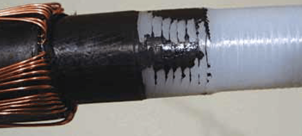
J. Is helical copper tape a robust shield design?
Helical copper tape functions just fine in paper insulated cable systems, since it is in oil and moisture is kept out by a lead sheath. Solid dielectric cable only has a polymer jacket to protect it and does not stop moisture from causing corrosion, initializing a process of arcing and pitting from the outside inwards which is commonly observed on aged cable.
Generally concentric neutral and longitudinally applied copper tapes have been shown to have a much better long-term performance.
K. Are there any standards we can use test solid dielectric cable systems?
Quality tests by cable and accessory manufacturers are performed on all new system components at the manufacturing plant prior to shipping and installation. All factory-built products must meet standards such as ICEA (Insulated Cable Engineers Association) or IEEE (Institute of Electrical and Electronics Engineers).
The manufacturers’ quality control tests require 50/60Hz partial discharge (PD) diagnostics at an elevated voltage, with generally better than 5 or 10pC sensitivity [Table 1]. These standards can be used to judge the performance of cable system in the field.

L. What can be done to enhance longevity?
The recipe for cable longevity is to push quality to the earliest point in the life of the cable system, and then minimize any extreme duty cycle events. As early in life as possible a cable system should be baselined with an offline 50/60Hz PD test to check for insulation issues and an IR test under high load conditions to check for connector issues.
Once any necessary repairs are complete, confirm sufficient over-voltage protection is installed at all significant impedance change points (primary cable end points). Finally, monitor the cable system for any extreme over-voltage or overloading events (including, re closing on faults, thumping, withstand or Hipot testing). If such events occur, a new baseline for the insulation and connector will need to be established.
Further Reading
THORNE & DERRICK
LV, MV & HV Jointing, Earthing, Substation & Electrical Eqpt
Thorne & Derrick International are specialist distributors of LV, MV & HV Cable Installation, Jointing, Duct Sealing, Substation & Electrical Equipment – servicing UK and global businesses involved in cable installations, cable jointing, substation, overhead line and electrical construction at LV, 11kV, 33kV and EHV.
THORNE & DERRICK Product Categories: Duct Seals | Cable Cleats | Cable Glands | Electrical Safety | Arc Flash Protection | Cable Jointing Tools | Cable Pulling | Earthing | Feeder Pillars | Cable Joints LV | Joints & Terminations MV HV

Sealing & Waterproofing
Densoband
Location: Glasgow, Scotland
Client: Transport Scotland
Contractor: Highway Barrier Solutions
Engineers: Scotland TranServe
Products: Densoband
Date: February 2015
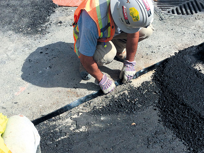
Densoband™ has been chosen for use in the installation of new crash barriers on the A898 Erskine Bridge, Glasgow. The volume of traffic has greatly increased since the bridge was opened in 1971.
Consequently the existing barriers in the central reserve were not providing appropriate levels of protection to the bridge towers and cable anchorages against impact from the largest HGV’s. Similarly, nearside barriers needed replacing in this project. All of the new barriers were designed by Flint & Neil, specialist bridge consultants.
The work was carried out for Transport Scotland who appointed Highway Barrier Solutions (HBS) as Principal Contractor. Scotland TranServe is the Engineer who managed the work.
The Glasgow branch of Briggs Amasco, specialists in industrial roofing and surface waterproofing recommended the use of Densoband in the reinstatement of the road asphalt adjoining the steel posts of the new crash barriers. Densoband was used to form a flexible weatherproof seal on the vertical joint face between the asphalt and steel.
Working in conjunction with Scotland TransServe, Briggs Amasco applied all the asphalt reinstatement and Densoband. Densoband is approved by the Department of Transport in the Manual of Contracts 7th Edition for use in asphalt wearing course joints.
➡ T&D stock and distribute Denso products. See Denso Mastic Duct Seal
DENSOBAND – Sealing Joints In Highway Construction & Maintenance
Densoband
Densoband™ is a polymer modified bitumen compound in strip form, used for sealing joints between asphalt to asphalt, concrete and road castings in road construction and bridge expansion joints. It can also be used for airport runway joints and light railway/tram construction to form a flexible seal between the track and the surrounding asphalt.
Containing filler, a flow control additive and a root deterrent, Densoband forms a flexible watertight seal which allows for road movement from cyclic traffic load and thermal changes to prevent cracking and subsequent erosion.

ABOUT DENSO
Denso North America Inc. is a subsidiary of Winn & Coales International, a leading manufacturer of anti-corrosion coatings that include Protal liquid epoxies, Denso petrolatum tapes, mastics, primers, bitumen tapes, butyl tapes, hot applied tapes, and a full line of marine pile protection systems. Winn & Coales was originally established as a business in London, England, in 1883, and the first petrolatum tape manufactured in the UK was Denso tape, manufactured under license by Winn & Coales (Denso) Limited.
Denso tape was developed over 80 years ago for the “Long Life Protection” of buried steel pipelines against corrosion. The Denso SeaShield Marine Systems include fiberglass forms, epoxy grouts, underwater epoxies, injectable epoxies, petrolatum tape and wrap systems.
Further Reading
Sealing & Waterproofing of Cable Ducts Using Densoseal 16A | Thames Water Project
Denso Mastic Duct Seal | Densoseal 16A Sealing Cable Ducts
Denso Bore-Wrap | Prevent Coating Damage During Pipeline Installations


Thorne & Derrick are Specialist Distributors to the UK and international Construction industry to provide safe and reliable LV HV Electrical Cable & Power Distribution Systems up to 66kV – we are highly customer responsive and absolutely committed to providing a world-class service.
Contact our UK Power Team for competitive quotations, fast delivery from stock and technical support or training on all LV-HV products.
Key Product Categories: Duct Seals | Cable Cleats | Cable Glands | Electrical Safety | Arc Flash Protection | Cable Jointing Tools | Cable Pulling | Earthing | Feeder Pillars | Cable Joints LV | Joints & Terminations MV HV

Electrical Safety Equipment
CATU ALED3
Live Line Electricity Voltage Alarm
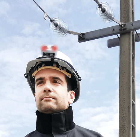
ALED3 from CATU is a distance live line electricity voltage alarm for ensuring the safety of operators while they are working within live powered environments.
The alarm will warn workers of the presence of an electric field from1kV to 66kV using a sound as well as a visual warning.
The ALED3 is compact and lightweight with a built in antenna and can be worn on a helmet, on the arm, on the belt, on the body. This live line electricity voltage alarm features a 360° detection sensor depending on the position of the device.
Live Line Voltage ALarm
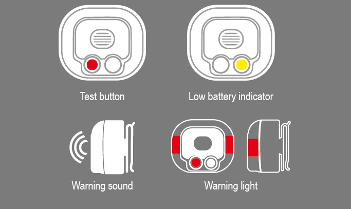
ALED3 Features
- The alarm is automatically triggered when the operator approaches an electric field and turns off when moved away from the source.
- 360º detection according to the positioning of the device which has multiple fixing possibilities (helmet, arms, belt, body).
- Compact and light with integrated antenna.
- Sound intensity: 75 dB
- Response time: < 1 s.
Live Line Electricity Voltage Alarm | CATU ALED3
CATU ALED3
Technical Specification
- Network voltage: 1-66 kV
- Frequency : 50-60 Hz
- Operating temperature: -5ºC / 45ºC
- Sound intensity: 75 dB
- Net weight: 85 g (including batteries).
- Dimensions: 66 x 56 x 39 mm.
- Protection index: IP64
- Power supply: 2 alkaline batteries AAA 1,5 V
- Standards: EN 61326-1: 2013 / EN 62311-1: 2008
- Marking: CE
| Distance |
Phase/Earth |
Phase/Phase |
| 1m |
1kV |
1.7kV |
| 2m |
2kV |
3.5kV |
| 3m |
5kV |
8.7kV |
| 4m |
10kV |
17.3kV |
| 4.5m |
14.5kV |
25.1kV |
| 5m* |
20kV |
34.6kV |
| 5.5m* |
27.5kV |
47.6kV |
| 6m* |
36kV |
62.4kV |
Voltages given as an indication, obtained in laboratory conditions using single-phase voltage on a 2-metre bar at 1.5 metres from the ground.
* Estimation based on trend line |
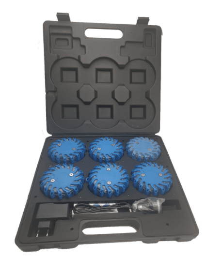
Blue LED signal lamps
CATU CD-129
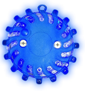 CATU CD-129 blue LED road flare signal lamps are used to alert and signal work on roads and railways. The LED signal lamps adhere to EN 61547 – IEC 61000-4-5:2014 and are supplied in a box which holds six 0.8 watt, 240 lumen LEDs and a 12V/24V car charger or 110V/220V wall charger.
When fully charged, the indicator light aside flares stop flashing and remain steady after 8 to 10 hours of usage. These blue LED signal lamps feature a simple start-up, several different lighting modes and are equipped with a magnet to enable the lamps to be fixed onto a metal surface.
CATU CD-129 have an impact resistant rating of IK07 and are waterproof to IP65.
CATU CD-129 Blue LED Road Flare Lamps
T&D are the UK’s largest stockist of CATU Electrical Safety Equipment of products for underground, overhead line and substation safety at LV, MV and HV cable networks.

Today’s outdoor cable terminations are factory produced and tested. Source Ivan Jovanovic, Director of Engineering Specialty Products with G&W Electric and associate member of PDi2.
Underground Electric Distribution
The Cost of Underground Electric Distribution Is Coming Down
By Mike Beehler | Mike Beehler & Associates
Special thanks To Martha Davis for Kind Permission to Republish this Article
Advancements in material science, construction methods and emerging technologies make 21st century costs for undergrounding T&D assets much more attractive for planners and engineers than ever before.
The old “rules of thumb” about the higher costs of T&D underground are no longer valid.
The costs are now coming down.
Innovation and continuous improvement programs have positively impacted underground costs in the areas of design, construction, operations and maintenance of new and existing feeders, underground residential distribution (URD) and service connections.
The state-of-the-art experience and science of modern cable systems around the world suggest properly installed and operated underground cable systems can safely and reliably serve customers significantly longer than overhead line components.
In addition, data is starting to show dramatically lower operation and maintenance expenses over the life of underground assets. These results trend toward the achievement of net-positive lifecycle value for underground with dramatically better resiliency.
Utilities are evaluating these intriguing concepts and the current tangible costs while considering the harder-to quantify benefits of safety, reliability and aesthetics on behalf of their customers in diverse service territories.
Material Science And Cable Design
Advancements in material science have changed many parts of the electric distribution system and the industry. Utilities are closely monitoring these advancements. Significantly longer cable life can be achieved using innovative semiconducting and insulating materials.
Semiconducting shield materials with smoother surfaces reduce stress enhancements and semiconducting jackets provide continuous grounding to dissipate overvoltage conditions more quickly. Enhanced insulation materials have demonstrated significantly longer life under accelerated wet-aging conditions.
“These enhancements contribute to underground cables that now are projected to last longer than the traditional overhead line,” said Brent Richardson, senior end-use marketing manager for Dow and an executive board member of the Power Delivery Intelligence Initiative (PDi2).
For example, a recent review of state-of-the-art cable science by Chatteron et al. at the Fall 2019 IEEE Power & Energy Society’s Insulated Conductor Committee meeting summarized that cables can last well beyond 100 years, which far surpasses the average 50-year wood pole life quoted by the North American Wood Pole Council.
“Stronger cable designs on larger reels cut civil design and construction costs by reducing the number of manholes needed, traffic control and public disruption, the number of joints and terminations, and cable handling costs,” noted Matt Raymond, division manager of Haugland Energy and a PDi2 associate member.
Old accessory designs relied heavily on field preparation of joint and termination primary insulation that could not be routinely pretested. Now, components use controlled molded stress control and can be 100% factory tested. These designs also have various features that reduce installation time and the rigor of work in varied field conditions.
Today’s cable joints and separable connectors are fully submersible, enabling uninterrupted power distribution by underground cable systems during storm surges and flooding. This makes them ideal components for coastal environments and strategic undergrounding programs aimed at reducing power restoration times.
3D Design
Today, 3D designs of distribution standards linked to complete material lists of parts and components are becoming more common n the industry.
Dimensionally accurate 3D standards for equipment applied to geographically positioned mapping for roads and rights-of-way help utilities to improve infrastructure by streamlining modern underground design.
Engineers regularly monitor and test new models of pad-mounted transformers, switchgear, cable splices and terminations as they develop and enhance the standards to which their systems are built.

Low-cost cable installation in South Carolina. Source Brian Hunter, regional manager of TT Technologies and associate member of PDi2
Planners and engineers are finding ways to reduce the cost of underground systems as they design and build the grid of the future. Here are a few examples of cable system design specifications that can save cost and increase component life:
1. Reducing the amount of copper used in typical North American medium-voltage, three-phase cables with concentric wire neutrals reduces cost and increases power transmission capabilities by restricting circulating currents that heat the cable from the outside.
Using cross-linked polyethylene (XLPE) instead of typical linear low-density polyethene increases the maximum cable jacket temperature rating, enabling utilities to reduce the amount of copper in a concentric neutral wire cable design without concern a fault on the system will overheat and damage the jacket.
2. Using range-taking shear-bolt conductor connectors instead of compression connectors can lower costs and reduce the likelihood of common installation mistakes, especially in highly loaded circuit applications. Typical compression connectors require a different size connector and compression tools for each conductor size.
Range taking shear-bolt conductor connectors can be used for multiple conductor sizes and their set screw design, which shears off at a specific tightness (torque value), reduces installation time and automatically removes the conductor oxidation. Skipping oxidation removal is a common root cause of overheating issues with applications using low-cost aluminum conductors.
3. Utilities that typically specify extra-thick cable insulation (133% or higher) can save costs by limiting insulation thickness to 100% levels and achieve the same performance.
Field studies show 100% insulation systems can perform just as well as overinsulated cable, provided overvoltage protection like surge arresters are properly installed at transitions — from overhead to underground — multiway (three-plus) intersections and circuit end points.
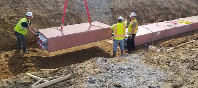
Precast duct bank installation. Source Forterra.
Construction Costs
The cost of installing underground cable in similar construction configurations can vary from as high as US$200/ft on the West Coast to as low as $20/ft in the southeastern U.S.
The cost of design and installation for underground cable systems can vary. Utilities like Dominion Energy Inc., Florida Power and Light Co. (FPL), Georgia Power, San Diego Gas & Electric (SDG&E), Pepco Holdings Inc. and WEC Energy Group Inc. have instituted strategic underground or underground system enhancement programs. In doing so, they have learned that regulations, population density, ground conditions and union vs. nonunion labor can contribute to unit-cost-per-foot differences.
WEC Energy provides a strong example of modern costs and benefits associated with a strategic undergrounding program, targeting approximately 2200 miles (3541 km) of distribution while concurrently installing automation equipment on 400 miles (644 km).
The costs for undergrounding are approximately $42/ft, as reported at the IEEE Insulated Conductors Committee meeting in late 2019. WEC Energy construction methods were 2% open cut, 50% plowing and 48% boring — demonstrating that new equipment designs and installation contractor methods continue to improve efficiencies.
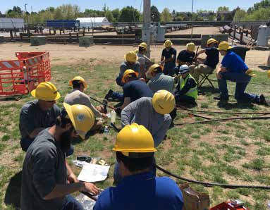
Installation skills training with immediate on-site factory-comparable testing and qualification. Source IMCORP.
According to the 2019 report, WEC Energy is on track to achieve 2% improvement in customer minutes interrupted (CMI) attributed to automation equipment and 16% CMI improvement because of strategic undergrounding. Reasons for undergrounding also vary. According to Martha Lachmayr, principal engineer of SDG&E, their major reasons for undergrounding are as follows:
1. Less frequent outages caused by exposed equipment
2. Beautification in the case of franchise agreements
3. Reduced risk of downed wires that could cause ignition in the high fire threat districts.
These utilities and their contractors developed innovative methods to take advantage of material, cable construction, design, installation, condition assessment and maintenance technologies to lower the life-cycle cost of underground systems.
While WEC Energy’s program is focused largely on more rural applications, other utilities are innovating on the urban front.
One example of an urban construction innovation is with precast manholes, equipment pads and duct banks that provide many schedule-related benefits and reduce the cost of construction.
“New developments in precast underground duct bank systems allow for burying utility lines more quickly and safely,” said Jeff Killin, vice president of engineered products for Forterra Inc. and a partner member of PDi2. “This means fewer crew members are needed in the trench and for less time, providing cost savings and reducing construction impacts.”
The traditional open-cut duct bank construction process requires multiple polyvinyl chloride (PVC) conduit runs that are stick built with individual sections of PVC conduit connected in sequence using PVC solvent cement. Then formwork is erected
around the installed conduits. Finally, thermal backfill or concrete is poured and must cure before work in the area resumes.
Added together, this traditional installation process is slow, labor intensive and subject to weather delays.
In contrast, precast duct bank sections consist of electrical conduits encased in engineered, prefabricated concrete sections, arriving at the jobsite ready for installation. Solvent cements are not required to join the sections, and no formwork, steel reinforcement or concrete is required. The need for concrete testing is eliminated at the jobsite, as quality tests are performed and recorded at certified precast concrete facilities.
Operations And Maintenance
From a lean-enterprise perspective, a large waste of human and material resources is overproduction, especially on non customer valued work. Utility financial overhead costs (that is, equipment procurement, specification, planning, switching order development and switching dispatch) as well as lead times (delays waiting for different work parties to complete sequential tasks) are substantial and difficult to track.
The importance of considering grid technologies that lower the frequency of waste-producing maintenance work orders cannot be overstated when comparing complete life-cycle costs. In evaluating public information from utility websites, Federal Energy Regulatory Commission (FERC) Form 1 and U.S. Securities and Exchange Commission (SEC) 10-K filings for five geographically diverse investor-owned utilities — namely,
The United Illuminating Co., FPL, Evergy, Arizona Public Service and Portland General Electric — the cost of underground distribution maintenance per mile is 3 times to 7 times lower than overhead. Year after year, utilities are reporting underground
Installation skills training with immediate on-site factory-comparable testing and qualification.
Even with traditionally low operating costs, the cost of maintaining underground cable systems can be dramatically decreased using proactive skills training and cable-condition profiling technology during construction and after damaging system events.
Cable system failure can occur years or decades after installation, but industry studies have found the root cause often is associated with installation or manufacturing issues.
“Over the last two decades, we have dissected thousands of field-installed substandard cables and accessories, and in nearly every case, there is evidence of a human or production anomaly precipitating the defect,” observed Ben Lanz, director of technology with IMCORP and an executive board member of PDi2.
“Once a failure occurs on aged cable, the fault location and repair process often create additional defects on both the subject and neighboring systems, thus dramatically increasing the cost of maintaining the system. Using 100% partial discharge testing at the factory and repeating this process in the field during commissioning can eliminate future operating and maintenance costs.”
In the case of post-installation damage from dig-ins or extreme operating conditions, implementing fault indicators, good operating practices and modern fault location techniques can dramatically minimize repair costs and additional system damage.
For example, after failures occur, good operating practices include confirming surge arresters are properly placed and using factory-test-comparable condition assessment techniques to profile repairs and neighboring lines for defects and degradation.
On aged cable systems experiencing repeated fault activity, cable-condition profiling technology can be used to extend the life by identifying weakened cable system components and directing lean work practices to only repair or replace what is necessary.
An example of such a program can be found in the T&D World article, “Managing Cable Assets,” by CenterPoint Energy Inc. (CNP). In this case study, CNP was challenged to address the reliability of approximately 18,000 underground residential distribution loops totaling 13,000 miles (20,922 km), where 27% of loops were comprised of cables causing 44% of the total system failures.
CNP used an all-capital process to assess the insulation condition of its cable systems. This process included a factory comparable partial discharge test, repairing all accessible components identified as substandard and scheduling any additional below-ground repair actions in the near future. By implementing this efficient process, CNP reported it had saved 65% of loop rehabilitation costs and achieved a 98% reduction in outages.
Evaluating Underground Options
Advancements in material science, construction methods and emerging technologies are lowering the 21st century costs of design, construction, and operations and maintenance of new and existing underground cable systems.
“The many benefits of undergrounding are obvious to today’s electric power consumers,” noted John Fluharty, II, a consultant with the Mears Group, a Quanta Services company, and a PDi2 executive board member. “As utilities across North America invest in a smart, reliable and resilient grid for the future, we believe undergrounding will increasingly emerge as the preferred alternative in many applications.”
Therefore, planners and engineers should evaluate underground distribution options on new construction and system upgrades based on careful study and a growing body of empirical data.
Acknowledgment
The author would like to thank the members of PDi2 for their contributions to this article, including Brent Richardson of Dow, Matt Raymond of Haugland Energy, Jeff Killin of Forterra, Ben Lanz of IMCORP, Ivan Jovanovic of G&W Electric Co., and Brian Hunter of TT Technologies.
MIKE BEEHLER is the national spokesperson for the Power Delivery Intelligence Initiative and is a registered Professional Engineer in AZ, FL, HI, TX, CO, KS, GA, and AL, a Fellow in the American Society of Civil Engineers, and a Member in IEEE and CIGRE. He has been married for 40 years, has four adult children and four grandchildren, and lives on Singer Island, Florida USA.
For More Information
Power Delivery Initiative (PDi2) | www.pdi2.org
Dow | www.dow.com
Haugland Energy | www.hauglandgroup.us/energy
TT Technologies | www.tttechnologies.com
Forterra | www.forterrabp.com
IMCORP | www.imcorp.com
Mears Group, A Quanta Service Company | www.mears.net
THORNE & DERRICK
Thorne & Derrick are national distributors of LV, MV & HV Cable Installation, Jointing, Substation & Electrical Equipment – servicing businesses involved in cabling, jointing, substation, earthing, overhead line and electrical construction at LV, 11kV, 33kV, 66kV and EHV. Supplying a complete range of power cable accessories to support the installation and maintenance of low/medium and high voltage power systems:
- Slip-on Cable Terminations
- Cold-shrink Cable Terminations
- Heat-shrink Cable Terminations
- Cable Joints – Heat & Cold-shrink
- Separable Connectors (Euromold)
- Surge Arresters & Switchgear/Transformer Bushings
Key Product Categories: Duct Seals | Cable Cleats | Cable Glands | Electrical Safety | Arc Flash Protection | Cable Jointing Tools | Cable Pulling | Earthing | Feeder Pillars | Cable Joints LV | Joints & Terminations MV HV


Pictured: 132kV Pfisterer Straight Joint Coupled With Pfisterer Connex Size 6 Plugs
Image Courtesy of: Richard Mason (EHV Cable Jointer) – Global Cabling Services Ltd.
Richard Mason is a leading name in the UK EHV Cable Jointing industry – a great guy and great jointer with proven track record across high profile projects installing leading products such as Pfisterer, 3M, Tyco Raychem, ABB and Nexans.
T&D are Main Distributors & Stockists for the Pfisterer range of Medium Voltage Power Products including Connex Plugs, Cable Jointing Tools, Sicon Connectors, Surge Arresters and Electrical Safety Equipment.


Jointers blog
Subscribe now to our POWER NEWSLETTER– a monthly email circulation packed with news, projects, videos, technical tips, training information, promotions, webinars, career opportunities and white papers.
Includes access to our popular JOINTERS BLOG with contributions from utility professionals, linesmen and cable jointers working on MV HV EHV cables and overhead lines typically at 11kV, 33kV, 66kV and up to 132kV.
15,000+ Subscribers. ➡