Cable Jointing Tools
Semi-Conducting Screens
STANDARD TECHNIQUE: CA2C/9
Relating to General Requirements for 11kV Cable Jointing
Extract from a Western Power Distribution Company Directive
The below guide explains the best way for the removal of semi-conducting screens.
Before commencing the level of PPE required for this operation shall be as the matrix given in General Requirement 3, your attention is drawn to the Use of Solvents General Requirement 1.
25.1 General
There are two types semi-conducting screens used on polymeric cables, fully bonded and easi-strip.
Virtually all polymeric cables used within WPD South have the easi-strip semiconducting screen.
While WPD Midlands have large amounts of easi-strip and fully bonded semi-conducting screens.
The method described here is for the removal of the easy-strip semi-conducting screen, which requires basic but effective cable jointer tooling and relative ease of removal to the installer.
Cable manufacturers currently supply two types of semi-conducting screen; both manufacturing methods can produce either easi-strip or fully bonded. With easi-strip semiconducting the material it’s important to have a compound such as ethylene vinyl acetate (EVA) which is strippable from the insulation.
In order for strippable screens to have sufficient tear strength during the removal from the insulation, it is necessary for the thickness to be approximately 1mm but the screen thickness can be thinner for harder materials. There are no such constraints with bonded screens and because the semiconducting materials are very expensive, thickness is kept to a minimum, 0.5mm being a typical figure.
The manufacturing methods are described as: –
- Monasil – identified by its smooth appearance.
- CCV (Continuous Catenary Vulcanising) – identified by its heavily ribbed appearance and characteristic acetophenone odour
- VCV (Vertical Catenary Vulcanising) – identified by its heavily ribbed appearance and characteristic acetophenone odour
25.2 Easi-strip Semi-conducting Screens
Note: – The method described below shall be THE ONLY APPROVED METHOD ADOPTED FOR USE within WPD for the removal of the easi-strip semi-conducting screens.
This phase of the jointing procedure must be undertaken with utmost care throughout this operation, failure to do so can be the cause or be a contributory factor in the failure of the joint or termination.
Cleanliness and attention to detail are vital, it is essential to avoid damaging the insulation at the semi-conducting screen termination, and any cuts or voids etc. will lead to the premature failure of the MV cable joint or termination.
2.1 Method of Removal
Refer to Drawing GR3D 6.25.1 whilst undertaking this General Requirement.
2.1.1 Mark the semi-conducting screen at its termination point with a white Chinagraph pencil.
2.1.2 Using PVC tape, apply (sticky side outermost for one complete turn) around the circumference of the cable at its termination point apply sufficient turns to provide a straight and square edge to guide the Abra file – Fig 1.
2.1.3 Using the Abra file with medium pressure, file evenly around the semi-conducting screen until the conductor insulation just shows – Fig 2.
Note: – The insulation must be seen continuously around the cable otherwise the semi-conducting screen may be lifted below its cable termination point.
2.1.4 Use a mirror to check the underside of the cable; there should be a smooth neat chamfer on what will be the remaining circumferential edge.
Note: – Where raggedness of the termination appears, run the Abra file with light pressure to remove high points; take care not to damage the insulation.
Ribbing of the semi-conducting screen may be removed by gently warming with a gas torch until the semi-conducting screen achieves a smooth surface.
2.1.5 Using the correct depth guarded knife (0.4mm for Prysmian 33kV & 0.6mm for Tratos 33kV cables) and starting just above the circumferential termination point make longitudinal scores spaced approximately 120° along the core length to its end – Fig 3.
Note: – Depending on cable size the three longitudinal scores may be reduced, two being the minimum otherwise undue stress is applied to the installers hands and cable.
Where there is extreme difficulty of drawing the depth guarded knife from the circumferential termination point to the cable end, and providing a cable tie is placed around the circumferential termination point to protect the shown insulation, the cable may be scored from the open end towards the circumferential termination point.
Utmost care must be given if using this alternative method, damage at the semiconducting screen termination point will result in failure.
2.1.6 Lift the semi-conducting screen at the open cable end and peel back the strips to completely remove – Fig 4.
2.1.7 Using aluminium oxide tape abrade the exposed insulation ensuring a smooth finish along its length and at the semi-conducting chamfer (any ribbing within the surface of the insulation must be abraded out to a smooth finish).
Note: – 400 grit is normally sufficient to provide this finish, but a start with 320 grit and finishing with 400 grit may be required.
2.1.8 Using an approved cable cleaner degreaser and white wipes, remove all traces of the semiconducting screen wiping from the cable end towards the termination point.
Note: – After each run change the wipe otherwise contact with semi-conducting material will come into contact with the insulation leaving possible tracking traces.
2.1.9 Finally remove the PVC tape applied in 2 and thoroughly check the insulation along its complete length ensuring its contamination free – Fig 5.

Removal of Semi-Conducting Screens (Polymeric Cables)
25.3 Fully Bonded Screens
This phase of the jointing procedure must be undertaken with utmost care throughout this operation, failure to do so can be the cause or be a contributory factor in the failure of the joint or termination.
Cleanliness and attention to detail are vital, it is essential to avoid damaging the insulation at the semi-conducting screen termination, and any cuts or voids etc. will lead to the premature failure of the joint or termination.
Note: – The stripping tool, Alroc CWB 18-60, which has been supplied to all the WPD Jointers on the 33kV Conversion course is designed for bonded screen cables ONLY and shall NOT BE USED on any EPR or XLPE EASI-STRIP CABLES.

Alroc CWB 18-60 Tool – Bonded Semiconductor Stripper | LV MV HV 11kV 33kV 66kV 132kV EHV Cable Jointing Tools
The bonded semi-con stripping tool issued to Midlands Jointers by Central Networks SHALL NOT be used on the 33kV system.
3.1 Method of Removal
Refer to Drawing GR3D 6.25.2 whilst undertaking this General Requirement.
The Alroc/Pfisterer tool works across the range of diameters over the semi-con screen of 18mm to 60mm.
Note: – THIS TOOL DOES NOT REQUIRE ANY SILICON GREASE TO OPERATE IN ADDITION THIS IS THE ONLY TOOL TO BE USED FOR BONDED SEMI-CON REMOVAL.
3.1.1 Ensure the cable is clean and straight.
3.1.2 Mark the semi-conducting screen at its termination point with a white Chinagraph pencil.
3.1.3 Set the tool stop to the required distance. Apply a roll spring to the white Chinagraph mark.
3.1.4 Close up the tool up using the large, red plastic knob, to provide a firm grip that will still allow the tool to rotate, as shown in GR3D 6.25.2.
3.1.5 Position the cutter at the front edge of the screen and set the depth of cut using the small metal knob as shown in GR3D 6.25.3. The adjustment is anticlockwise to increase the depth of cut, clockwise to decrease. If necessary, practice on a scrap piece of cable to obtain the correct depth setting. The ideal setup will have two thirds of the removed material to be the black semi-con and one third of the removed material being the translucent XLPE insulation.
3.1.6 With the correct depth set, now rotate the whole tool using the rear handle, in the direction of the arrow that is printed onto the body of the toool – as the tool is rotated it will move progressively down the cable, peeling the screen. Do not apply excess pressure. The selected depth setting should produce a clean, smooth cut free of black semi-conducting material.
3.1.7 When the required screen termination position is reached, the tool stop will come in contact with the roll spring thus providing clean screen edge and prevent the tool from moving down the cable. Continue to rotate the tool until a clean cut screen edge is produced. Open the tool and remove the tool on completion.
3.1.8 After the tool is removed, examine the surface of the insulation to ensure all semiconducting layer has been removed.
3.1.9 Using aluminium oxide tape, abrade the exposed insulation ensuring a smooth finish along its length and at the semi-conducting chamfer (any ribbing within the surface of the insulation must be abraded out to a smooth finish).
Note: – 400 grit is normally sufficient to provide this finish, but a start with 320 grit and finishing with 400 grit may be required.
3.1.10 Using the approved De-Solvit 1000FD degreaser and white wipes, remove all traces of the semi-conducting screen wiping from the cable end towards the termination point.

Jointers blog
Subscribe now to our POWER NEWSLETTER– a monthly email circulation packed with news, projects, videos, technical tips, training information, promotions, webinars, career opportunities and white papers.
Includes access to our popular JOINTERS BLOG with contributions from utility professionals, linesmen and cable jointers working on MV HV EHV cables and overhead lines typically at 11kV, 33kV, 66kV and up to 132kV.
15,000+ Subscribers. ➡ 
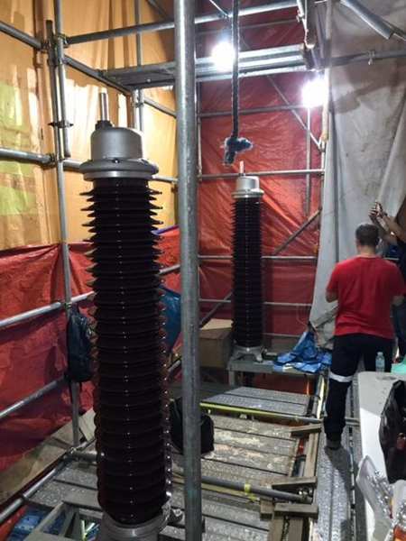
Image Courtesy: Dave Boyd EHV Cable Jointer. Owner/Company Director of HV Cablepower Pty Ltd
abb
ABB is a pioneering technology leader that works closely with utilities, industry, transportation and infrastructure customers to write the future of industrial digitalisation and realize value.

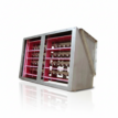
ABB APECB 170 Cable Terminations
This cable termination consists of an insulator installed on a box body made of aluminium castings. The box body consists partly of insulating material, which provides an insulated installation. The base part is to be installed on a bracket.
The electrical stress control component is a pre-molded rubber stress cone.
The insulator has sheds of short-long type and is filled with synthetic insulating oil. The composite insulator design includes grey silicone rubber sheds and a fibreglass reinforced epoxy resin hollow core.
It is light-weight and less sensitive for outer damages. The porcelain insulators are available in brown on request. A bolt clamp in the top fitting is used to connect the conductor to the top bolt. Top bolt and bolt clamp are included in the kit.
ABB APECB 170 Cable Terminations are used for installations in which the termination is to be used as a fixed connection point and meets the requirements of:
- IEC 60840, < 170 kV
- IEC 62067, 245–420 kV
- IEEE 48
With the technical, commercial and engineering support of ABB Power Products divisions, T&D can deliver Fuses, Transformers, Surge Arresters, Vacuum Contactors and Capacitors for the protection and distribution of medium voltage and high voltage electricity and cable systems.
Jointers blog
Subscribe now to our POWER NEWSLETTER– a monthly email circulation packed with news, projects, videos, technical tips, training information, promotions, webinars, career opportunities and white papers.
Includes access to our popular JOINTERS BLOG with contributions from utility professionals, linesmen and cable jointers working on MV HV EHV cables and overhead lines typically at 11kV, 33kV, 66kV and up to 132kV.
15,000+ Subscribers. ➡
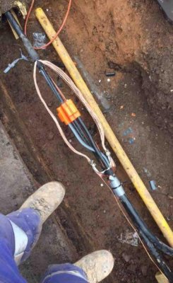 Image Courtesy of: Lee Richards : Cable Jointer LV, 11kV, 33kV at Power On Connections
Pictured: Live Self-Connect Wavecon Service Breech Joint (LV Low Voltage)
Thorne & Derrick asked Lee, what is your preferred method for stripping cable sheath from this type of waveform cable?
“With the existing mains cable, I cut a 2 inch flap with an insulated cable knife to then locate the centre of the waveform. I then begin marking up measurements to remove the remaining over sheath to the jointing instruction measurement,” explained Lee.
Thorne & Derrick
Specialist Electrical Distributor
Established since 1985, T&D distribute the most extensive range of LV, MV & HV Cable Jointing, Terminating, Pulling & Installation Equipment – contact us today for a competitive quotation.
Key Products : MV Joints & Terminations, Cable Cleats, Duct Seals, Cable Transits, Underground Cable Protection, Jointing Tools, Feeder Pillars, Cable Duct, Earthing & Lightning Protection, Electrical Safety, Cable Glands, Arc Flash Protection & Fusegear.
Distributors for : 3M, Pfisterer, Nexans Euromold, Elastimold, Catu, Roxtec, Emtelle, Centriforce, Lucy Zodion, Alroc, Hivotec, Cembre, Prysmian, Ellis Patents, ABB & Furse.
Jointers blog
Subscribe now to our POWER NEWSLETTER– a monthly email circulation packed with news, projects, videos, technical tips, training information, promotions, webinars, career opportunities and white papers.
Includes access to our popular JOINTERS BLOG with contributions from utility professionals, linesmen and cable jointers working on MV HV EHV cables and overhead lines typically at 11kV, 33kV, 66kV and up to 132kV.
15,000+ Subscribers. ➡
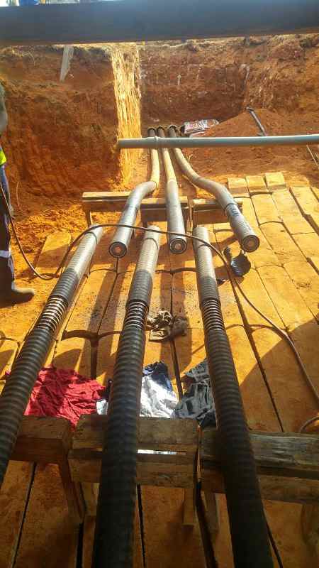
Image: Marnus Van Deventer | High Voltage Cable Jointer
Brugg Cables
Brugg Cables stands for integrated solutions, competence and Swiss quality in power distribution and data transmission.

High Voltage Cable Accessories for Polymer Cables
- HV Cable Terminations for Polymer Cables
- Outdoor terminations with porcelain insulator for polymer cables
- Outdoor terminations with composite insulator for polymer cables
- GIS terminations for polymer cables
- Dry type plug-in terminations for polymer cables
- Transformer terminations for polymer cables
- HV Cable Joints for Polymer Cables
- Slip-on joints for polymer cables up to 72.5 kV
- Slip-on joints for polymer cables up to 145 kV
- Slip-on joints for polymer cables up to 170 kV
- Slip-on joints for polymer cables up to 245 kV
- Slip-on joints for polymer cables up to 550 kV
High Voltage Cable Accessories for Oil-filled Cables
- Cable Terminations for Oil-filled Cables
- Outdoor terminations with porcelain insulator for oil-filled cables
- Outdoor terminations with composite insulator for oil-filled cables
- GIS terminations for oil-filled cables
- Transformer terminations for oil-filled cables
- Cable Joints for Oil-filled Cables
- Straight-through joints for oil-filled cables
- Stop joints for oil-filled cables
Jointers blog
Subscribe now to our POWER NEWSLETTER– a monthly email circulation packed with news, projects, videos, technical tips, training information, promotions, webinars, career opportunities and white papers.
Includes access to our popular JOINTERS BLOG with contributions from utility professionals, linesmen and cable jointers working on MV HV EHV cables and overhead lines typically at 11kV, 33kV, 66kV and up to 132kV.
15,000+ Subscribers. ➡
Image: Daniel Betts – 33KV 11KV LV Cable Jointer at Western Power Distribution
Pictured: LSF Mains Straight Resin Filled Joint 185-300sqmm 4 Core SNE
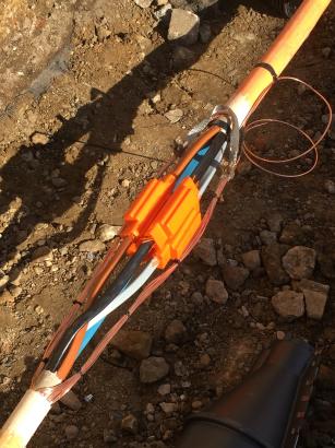
Resin Filled Joint
The 3 part resin cable joint shows the neutral conductor with the blue core at the bottom of the cable joint. The earth wires from both sides of the cable joint are in a BCNE connector with an equalisation bond and copper earth tail – they are required to extend out from the connector 5mm either side of the cable. A black mastic water block is wrapped around the earth tail by the cable jointer.
Jointers blog
Subscribe now to our POWER NEWSLETTER– a monthly email circulation packed with news, projects, videos, technical tips, training information, promotions, webinars, career opportunities and white papers.
Includes access to our popular JOINTERS BLOG with contributions from utility professionals, linesmen and cable jointers working on MV HV EHV cables and overhead lines typically at 11kV, 33kV, 66kV and up to 132kV.
15,000+ Subscribers. ➡